EP0141336A1 - Méthode de raccord de tuyau et structure à cet effet - Google Patents
Méthode de raccord de tuyau et structure à cet effet Download PDFInfo
- Publication number
- EP0141336A1 EP0141336A1 EP84112470A EP84112470A EP0141336A1 EP 0141336 A1 EP0141336 A1 EP 0141336A1 EP 84112470 A EP84112470 A EP 84112470A EP 84112470 A EP84112470 A EP 84112470A EP 0141336 A1 EP0141336 A1 EP 0141336A1
- Authority
- EP
- European Patent Office
- Prior art keywords
- joint member
- cylindrical joint
- pipe
- pipes
- center
- Prior art date
- Legal status (The legal status is an assumption and is not a legal conclusion. Google has not performed a legal analysis and makes no representation as to the accuracy of the status listed.)
- Granted
Links
- 238000000034 method Methods 0.000 title claims abstract description 13
- 230000006835 compression Effects 0.000 claims description 8
- 238000007906 compression Methods 0.000 claims description 8
- 239000002184 metal Substances 0.000 claims description 4
- 239000000956 alloy Substances 0.000 claims description 2
- 229910045601 alloy Inorganic materials 0.000 claims description 2
- 239000000919 ceramic Substances 0.000 claims description 2
- QVGXLLKOCUKJST-UHFFFAOYSA-N atomic oxygen Chemical compound [O] QVGXLLKOCUKJST-UHFFFAOYSA-N 0.000 description 4
- 229910052760 oxygen Inorganic materials 0.000 description 4
- 239000001301 oxygen Substances 0.000 description 4
- 229910000831 Steel Inorganic materials 0.000 description 2
- 239000010959 steel Substances 0.000 description 2
- 238000007747 plating Methods 0.000 description 1
Images

Classifications
-
- F—MECHANICAL ENGINEERING; LIGHTING; HEATING; WEAPONS; BLASTING
- F16—ENGINEERING ELEMENTS AND UNITS; GENERAL MEASURES FOR PRODUCING AND MAINTAINING EFFECTIVE FUNCTIONING OF MACHINES OR INSTALLATIONS; THERMAL INSULATION IN GENERAL
- F16L—PIPES; JOINTS OR FITTINGS FOR PIPES; SUPPORTS FOR PIPES, CABLES OR PROTECTIVE TUBING; MEANS FOR THERMAL INSULATION IN GENERAL
- F16L13/00—Non-disconnectable pipe joints, e.g. soldered, adhesive, or caulked joints
- F16L13/14—Non-disconnectable pipe joints, e.g. soldered, adhesive, or caulked joints made by plastically deforming the material of the pipe, e.g. by flanging, rolling
- F16L13/141—Non-disconnectable pipe joints, e.g. soldered, adhesive, or caulked joints made by plastically deforming the material of the pipe, e.g. by flanging, rolling by crimping or rolling from the outside
-
- B—PERFORMING OPERATIONS; TRANSPORTING
- B21—MECHANICAL METAL-WORKING WITHOUT ESSENTIALLY REMOVING MATERIAL; PUNCHING METAL
- B21D—WORKING OR PROCESSING OF SHEET METAL OR METAL TUBES, RODS OR PROFILES WITHOUT ESSENTIALLY REMOVING MATERIAL; PUNCHING METAL
- B21D39/00—Application of procedures in order to connect objects or parts, e.g. coating with sheet metal otherwise than by plating; Tube expanders
- B21D39/04—Application of procedures in order to connect objects or parts, e.g. coating with sheet metal otherwise than by plating; Tube expanders of tubes with tubes; of tubes with rods
-
- Y—GENERAL TAGGING OF NEW TECHNOLOGICAL DEVELOPMENTS; GENERAL TAGGING OF CROSS-SECTIONAL TECHNOLOGIES SPANNING OVER SEVERAL SECTIONS OF THE IPC; TECHNICAL SUBJECTS COVERED BY FORMER USPC CROSS-REFERENCE ART COLLECTIONS [XRACs] AND DIGESTS
- Y10—TECHNICAL SUBJECTS COVERED BY FORMER USPC
- Y10T—TECHNICAL SUBJECTS COVERED BY FORMER US CLASSIFICATION
- Y10T29/00—Metal working
- Y10T29/49—Method of mechanical manufacture
- Y10T29/49826—Assembling or joining
- Y10T29/49908—Joining by deforming
- Y10T29/49909—Securing cup or tube between axially extending concentric annuli
- Y10T29/49913—Securing cup or tube between axially extending concentric annuli by constricting outer annulus
-
- Y—GENERAL TAGGING OF NEW TECHNOLOGICAL DEVELOPMENTS; GENERAL TAGGING OF CROSS-SECTIONAL TECHNOLOGIES SPANNING OVER SEVERAL SECTIONS OF THE IPC; TECHNICAL SUBJECTS COVERED BY FORMER USPC CROSS-REFERENCE ART COLLECTIONS [XRACs] AND DIGESTS
- Y10—TECHNICAL SUBJECTS COVERED BY FORMER USPC
- Y10T—TECHNICAL SUBJECTS COVERED BY FORMER US CLASSIFICATION
- Y10T29/00—Metal working
- Y10T29/49—Method of mechanical manufacture
- Y10T29/49826—Assembling or joining
- Y10T29/49908—Joining by deforming
- Y10T29/49925—Inward deformation of aperture or hollow body wall
- Y10T29/49927—Hollow body is axially joined cup or tube
Definitions
- This method relates to a pipe connection method and connecting structure. More specifically, it relates to the connection method and connecting structure of lance pipe used to blow oxygen into the steel bath in, for example, an open-hearth furnace or electric furnace.
- the lance pipe used to blow oxygen into the steel bath in an open-hearth furnace or electric furnace can be exposed to, for example, temperatures of 1800°C and therefore wear easily. Pipes which have become shorter can be reused by connecting them with suitable joints. In this case the lance pipes must be connected by air-tight joints to prevent oxygen from leaking out.
- the first purpose of this invention is to provide a connection method and connecting structure that will improve the air tightness of lance pipe connections.
- the second purpose of this invention is to provide a connection method and connecting structure which permit both ends of a cylindrical joint member to be compressed into the ends of the lance pipes simultaneously.
- the third purpose of this invention is to provide a connection method and connecting structure which make it easy for both lance pipe ends to be positioned near the center of the cylindrical joint member.
- both ends and the center of the cylindrical joint member are compressed when fitted over the ends of the lance pipes, thus insuring good air tightness at two locations.
- ring-shaped grooves can be cut near both ends of the joint member to make it easier to compress the ends into the ends of the lance pipes, or a protrusion can be formed in the center of the inside of the joint member to improve contact with the lance pipes.
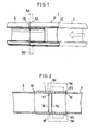
- the joint member 1 is made of metal and formed into a cylindrical shape.
- One end lA of this joint member 1 is fitted over the end of the first metal pipe 3 sc that the end of the pipe 3 reaches almost to the center of the joint member 1.
- the end lA of the joint member 1 is formed in the shape of a semicircular arc. It is compressed by the two compression jigs 5A and 5B which are located opposite to each other, and the edge 1B of the end lA of the joint member 1 cuts sharply into the first pipe 3 to seal the joint air-tight and to hold it in place.
- the other end lC of the joint member 1 is fitted over the end of the other pipe to be connected.
- the second pipe 7 is positioned so as to leave an appropriate gap between the end of the first pipe 3 and the end of the second pipe 7.
- the center 1D and the end lC of the joint member 1 are compressed by the compression jigs 9A and 9B which are positioned opposite to each other and each of which includes a first compression part 9F which is shaped in a semicircular arc and sharpened with a nearly triangular cross-section, and a second compression part 9S which has an appropriate shape.
- the edge lE of the end lC of the joint member 1 cuts sharply into the second pipe 7 to seal the joint air-tight and hold it in place.
- center 1D of the joint member 1 butts in between the end 3E of the first pipe 3 and the end 7E of the second pipe 7 to reinforce the air tightness.
- the compressive connection of the ends lA and 1C of the joint member 1 to the first and second pipes 3 and 7 creates an airtightsection at each end of the joint.
- a second pair of airtight contacts is created by the compression of the ends 3E and 7E of the first and second pipes 3 and 7 on either side of the center 1D of the joint member 1.
- This pair of double airtight seals improves the air tightness of the joint.
- the inside of the joint member 1 to be lined with a layer of soft metal, alloy or ceramic by a process such as plating or calorizing.
- Figs.3 and 4 show another embodiment of this invention.
- ring-shaped grooves 1G are cut around the joint member 1 near the ends lA and 1C.
- both ends lA and 1C and the center 1D of the joint member 1 can be compressed simultaneously by the compression jigs 11A and 11B each of which has the semicircular compression parts 11F, 11S and 11T, in order to join the joint member 1 to the first and second pipes 3 and 7. That is to say, as shown in Fig.4, the joint member 1 is compressed simultaneously at several locations to join it to the first and second pipes 3 and 7, which in this embodiment increases the efficiency of the operation.
- Fig.5 shows still another embodiment.
- this embodiment there is a protrusion 1P on the inside of the joint member 1 at the center.
- the first and second pipes 3 and 7 and the joint member 1 are compressed at both ends and also at the center of the joint member 1 in such a way that the ends of the pipes cut into the joint member and the ends of the joint member cut into the pipes, double airtight seals are obtained, improving the air tightness.
- the positions of the first and second pipes 3 and 7 can be accurately and rapidly merely by inserting them into opposite ends of the joint member 1 until they butt up against the protrusion.
Landscapes
- Engineering & Computer Science (AREA)
- Mechanical Engineering (AREA)
- General Engineering & Computer Science (AREA)
- Mutual Connection Of Rods And Tubes (AREA)
- Non-Disconnectible Joints And Screw-Threaded Joints (AREA)
- Joining Of Building Structures In Genera (AREA)
- Gasket Seals (AREA)
Applications Claiming Priority (2)
| Application Number | Priority Date | Filing Date | Title |
|---|---|---|---|
| JP198343/83 | 1983-10-25 | ||
| JP58198343A JPS6091085A (ja) | 1983-10-25 | 1983-10-25 | 管継手 |
Publications (2)
| Publication Number | Publication Date |
|---|---|
| EP0141336A1 true EP0141336A1 (fr) | 1985-05-15 |
| EP0141336B1 EP0141336B1 (fr) | 1988-01-20 |
Family
ID=16389539
Family Applications (1)
| Application Number | Title | Priority Date | Filing Date |
|---|---|---|---|
| EP84112470A Expired EP0141336B1 (fr) | 1983-10-25 | 1984-10-16 | Méthode de raccord de tuyau et structure à cet effet |
Country Status (5)
| Country | Link |
|---|---|
| US (1) | US4624489A (fr) |
| EP (1) | EP0141336B1 (fr) |
| JP (1) | JPS6091085A (fr) |
| DE (1) | DE3468926D1 (fr) |
| ES (1) | ES8507250A1 (fr) |
Cited By (1)
| Publication number | Priority date | Publication date | Assignee | Title |
|---|---|---|---|---|
| WO2016015703A1 (fr) * | 2014-07-28 | 2016-02-04 | Sosta Gmbh & Co. Kg | Procédé servant à fabriquer un tuyau multicouche |
Families Citing this family (18)
| Publication number | Priority date | Publication date | Assignee | Title |
|---|---|---|---|---|
| US4765051A (en) * | 1986-10-17 | 1988-08-23 | Helterbrand David L | Method for constructing a locking bar for use in a spare tire carrier |
| US5378074A (en) * | 1992-08-24 | 1995-01-03 | Fabex, Incorporated | Tubular connection |
| US5405176A (en) * | 1994-02-15 | 1995-04-11 | Mcdonnell Douglas Corporation | High pressure mechanical seal |
| RU2155291C1 (ru) * | 1999-02-09 | 2000-08-27 | Общество с ограниченной ответственностью "Инженерно-производственный центр" | Способ неразъемного соединения металлических труб |
| DE50111838D1 (de) * | 2000-09-22 | 2007-02-22 | Faurecia Abgastechnik Gmbh | Toleranzausgleichende lösbare und nicht lösbare Rohrverbindungen |
| DE10058592A1 (de) * | 2000-11-25 | 2002-06-06 | Bosch Gmbh Robert | Werkstück |
| RU2205319C2 (ru) * | 2001-04-19 | 2003-05-27 | Потапов Валерий Тимофеевич | Способ соединения труб |
| RU2213898C2 (ru) * | 2001-12-26 | 2003-10-10 | Карпов Валентин Михайлович | Способ изготовления насосно-компрессорных и бурильных труб |
| WO2003071098A1 (fr) * | 2002-02-25 | 2003-08-28 | Steffen, Robertson & Kirsten (South Africa) (Pty) Ltd And William David Ortlepp | Boulon d'ancrage |
| RU2232312C2 (ru) * | 2002-06-21 | 2004-07-10 | Российский Федеральный Ядерный Центр - Всероссийский Научно-Исследовательский Институт Экспериментальной Физики | Соединение цилиндрических деталей |
| RU2245478C2 (ru) * | 2003-03-11 | 2005-01-27 | Общество с ограниченной ответственностью "Инженерно-производственный центр" (ООО "ИПЦ") | Способ неразъемного муфтового соединения металлических труб с внутренним покрытием |
| DE102005011384A1 (de) * | 2005-03-11 | 2006-09-14 | Centrotherm Elektrische Anlagen Gmbh & Co. Kg | Gasdichtes Verbindungselement mit Bajonettverschluss |
| KR101187039B1 (ko) * | 2008-02-13 | 2012-09-28 | 주식회사 만도 | 감쇠력 가변 댐퍼의 솔레노이드밸브 조립체 및 그것의조립방법 |
| DE102010042538A1 (de) * | 2010-10-15 | 2012-04-19 | Ford Global Technologies, Llc | Verfahren zum Fügen von Bauteilen aus hochfestem Stahl |
| WO2013054821A1 (fr) * | 2011-10-11 | 2013-04-18 | 日本精工株式会社 | Colonne de direction et son procédé de production |
| RU2466324C1 (ru) * | 2011-11-03 | 2012-11-10 | Федеральное Государственное Унитарное Предприятие "Государственный научно-производственный ракетно-космический центр "ЦСКБ-Прогресс" (ФГУП "ГНПРКЦ "ЦСКБ-Прогресс") | Способ неразъемного соединения труб |
| DE102011088388A1 (de) * | 2011-12-13 | 2013-06-13 | Novopress Gmbh Pressen Und Presswerkzeuge & Co. Kg | Verfahren zur Herstellung einer Rohrverbindung mittels Pressfitting sowie Presswerkzeug |
| RU2557153C1 (ru) * | 2014-04-23 | 2015-07-20 | Общество с ограниченной ответственностью "Инженерно-производственный центр" | Способ неразъемного муфтового соединения металлических труб |
Citations (3)
| Publication number | Priority date | Publication date | Assignee | Title |
|---|---|---|---|---|
| DE233241C (fr) * | ||||
| US4061367A (en) * | 1974-08-26 | 1977-12-06 | Moebius Kurt Otto | Lockring tube joint |
| DE3226868A1 (de) * | 1981-10-01 | 1983-04-21 | Daiwa Steel Tube Industries Co., Ltd., Osaka | Dauerhaft dichte gewindelose rohrverbindung |
Family Cites Families (16)
| Publication number | Priority date | Publication date | Assignee | Title |
|---|---|---|---|---|
| US2192914A (en) * | 1938-11-30 | 1940-03-12 | James N Ice | Method of connecting conduit sections |
| US3343252A (en) * | 1964-03-03 | 1967-09-26 | Reynolds Metals Co | Conduit system and method for making the same or the like |
| US3596939A (en) * | 1968-08-15 | 1971-08-03 | Glenn J Gibson | Tube joint having sealing and crimping means |
| US3498648A (en) * | 1968-08-22 | 1970-03-03 | Boeing Co | High temperature and pressure tube fitting |
| DE1809491A1 (de) * | 1968-11-13 | 1970-05-27 | Kronprinz Ag | Rohrverbindung |
| US4035007A (en) * | 1970-07-02 | 1977-07-12 | Raychem Corporation | Heat recoverable metallic coupling |
| US3752348A (en) * | 1971-08-30 | 1973-08-14 | Ford Motor Co | Motor vehicle electrically heated windshield and backlight system |
| JPS5010008A (fr) * | 1973-05-23 | 1975-02-01 | ||
| DE2332241C3 (de) * | 1973-06-25 | 1982-08-19 | Kurt Otto Palos Verdes Penninsula Calif. Moebius | Rohrverbindung |
| US3893718A (en) * | 1973-11-23 | 1975-07-08 | Jonathan S Powell | Constricted collar insulated pipe coupling |
| JPS5141582A (en) * | 1974-10-04 | 1976-04-07 | Hitachi Cable | Koatsuhoosuno taiatsushikenki |
| US3956815A (en) * | 1975-05-06 | 1976-05-18 | Amp Incorporated | Explosively propelled equal mass tubular member swaging tool |
| US4257155A (en) * | 1976-07-26 | 1981-03-24 | Hunter John J | Method of making pipe coupling joint |
| US4231596A (en) * | 1978-03-17 | 1980-11-04 | Ridenour Ralph Gaylord | Tubing joint assembly |
| JPS5588939A (en) * | 1978-12-27 | 1980-07-05 | Nippon Benkan Kogyo Kk | Joint connection method |
| US4482174A (en) * | 1980-09-15 | 1984-11-13 | Lokring | Apparatus and method for making a tube connection |
-
1983
- 1983-10-25 JP JP58198343A patent/JPS6091085A/ja active Pending
-
1984
- 1984-10-16 EP EP84112470A patent/EP0141336B1/fr not_active Expired
- 1984-10-16 US US06/661,418 patent/US4624489A/en not_active Expired - Fee Related
- 1984-10-16 DE DE8484112470T patent/DE3468926D1/de not_active Expired
- 1984-10-24 ES ES537041A patent/ES8507250A1/es not_active Expired
Patent Citations (3)
| Publication number | Priority date | Publication date | Assignee | Title |
|---|---|---|---|---|
| DE233241C (fr) * | ||||
| US4061367A (en) * | 1974-08-26 | 1977-12-06 | Moebius Kurt Otto | Lockring tube joint |
| DE3226868A1 (de) * | 1981-10-01 | 1983-04-21 | Daiwa Steel Tube Industries Co., Ltd., Osaka | Dauerhaft dichte gewindelose rohrverbindung |
Cited By (1)
| Publication number | Priority date | Publication date | Assignee | Title |
|---|---|---|---|---|
| WO2016015703A1 (fr) * | 2014-07-28 | 2016-02-04 | Sosta Gmbh & Co. Kg | Procédé servant à fabriquer un tuyau multicouche |
Also Published As
| Publication number | Publication date |
|---|---|
| ES537041A0 (es) | 1985-08-16 |
| JPS6091085A (ja) | 1985-05-22 |
| ES8507250A1 (es) | 1985-08-16 |
| DE3468926D1 (en) | 1988-02-25 |
| US4624489A (en) | 1986-11-25 |
| EP0141336B1 (fr) | 1988-01-20 |
Similar Documents
| Publication | Publication Date | Title |
|---|---|---|
| US4624489A (en) | Pipe connection method and connecting structure | |
| US4433861A (en) | Arrangement for connecting two pipe ends | |
| GR3035792T3 (en) | Method and preformed part for manufacturing a press-fitting connection between two pipes | |
| US4541659A (en) | Permanently sealed threadless joint | |
| EP1089321A1 (fr) | Tube d'arc en céramique | |
| EP0229214B1 (fr) | Raccord à bride pour tuyau exempt de fuite et résistant aux vibrations | |
| CN109915676A (zh) | 管道连接结构 | |
| US2440298A (en) | Method of brazing steel shaft and flange assemblies | |
| JPH03292488A (ja) | 管継手 | |
| IE45192B1 (en) | Ethods for repairing underwater pipelines | |
| FR2356463A1 (fr) | Procede et outillage pour l'assemblage de tubes | |
| JPH043174Y2 (fr) | ||
| JPH04116289A (ja) | 圧縮機のパイプ接続構造 | |
| JPS56167892A (en) | Air tight joint structure for enclosed compressor | |
| CN108237336A (zh) | 一种用于加强管件焊接的方法及其焊接结构 | |
| JPH02502051A (ja) | 整列用ボスを有する集合アセンブリ | |
| JPS61111726A (ja) | 鋼管の管端加工方法 | |
| CN116538364A (zh) | 一种适用于气动快插接头的卡爪机构 | |
| KR100505929B1 (ko) | 압축기 및 압축기의 배관연결방법 | |
| CN212642666U (zh) | 一种压裂滑套用活动球座 | |
| CN213684449U (zh) | 一种压缩机排气管 | |
| JPS6358679B2 (fr) | ||
| US3251525A (en) | Apparatus for sealing tubulation | |
| KR0134329Y1 (ko) | 초고압 케이블의 단말 구조 | |
| JPH07185804A (ja) | ステンレス管の溶接方法及び溶接用継手 |
Legal Events
| Date | Code | Title | Description |
|---|---|---|---|
| PUAI | Public reference made under article 153(3) epc to a published international application that has entered the european phase |
Free format text: ORIGINAL CODE: 0009012 |
|
| AK | Designated contracting states |
Designated state(s): BE DE FR GB IT NL SE |
|
| 17P | Request for examination filed |
Effective date: 19850426 |
|
| 17Q | First examination report despatched |
Effective date: 19860502 |
|
| GRAA | (expected) grant |
Free format text: ORIGINAL CODE: 0009210 |
|
| AK | Designated contracting states |
Kind code of ref document: B1 Designated state(s): BE DE FR GB IT NL SE |
|
| ITF | It: translation for a ep patent filed | ||
| REF | Corresponds to: |
Ref document number: 3468926 Country of ref document: DE Date of ref document: 19880225 |
|
| ET | Fr: translation filed | ||
| PLBE | No opposition filed within time limit |
Free format text: ORIGINAL CODE: 0009261 |
|
| STAA | Information on the status of an ep patent application or granted ep patent |
Free format text: STATUS: NO OPPOSITION FILED WITHIN TIME LIMIT |
|
| 26N | No opposition filed | ||
| ITTA | It: last paid annual fee | ||
| PGFP | Annual fee paid to national office [announced via postgrant information from national office to epo] |
Ref country code: FR Payment date: 19921006 Year of fee payment: 9 |
|
| PGFP | Annual fee paid to national office [announced via postgrant information from national office to epo] |
Ref country code: GB Payment date: 19921007 Year of fee payment: 9 |
|
| PGFP | Annual fee paid to national office [announced via postgrant information from national office to epo] |
Ref country code: SE Payment date: 19921014 Year of fee payment: 9 |
|
| PGFP | Annual fee paid to national office [announced via postgrant information from national office to epo] |
Ref country code: BE Payment date: 19921016 Year of fee payment: 9 |
|
| PGFP | Annual fee paid to national office [announced via postgrant information from national office to epo] |
Ref country code: NL Payment date: 19921031 Year of fee payment: 9 |
|
| PGFP | Annual fee paid to national office [announced via postgrant information from national office to epo] |
Ref country code: DE Payment date: 19921130 Year of fee payment: 9 |
|
| PG25 | Lapsed in a contracting state [announced via postgrant information from national office to epo] |
Ref country code: GB Effective date: 19931016 |
|
| PG25 | Lapsed in a contracting state [announced via postgrant information from national office to epo] |
Ref country code: SE Effective date: 19931017 |
|
| PG25 | Lapsed in a contracting state [announced via postgrant information from national office to epo] |
Ref country code: BE Effective date: 19931031 |
|
| BERE | Be: lapsed |
Owner name: DAIWA STEEL TUBE INDUSTRIES CO. LTD Effective date: 19931031 |
|
| PG25 | Lapsed in a contracting state [announced via postgrant information from national office to epo] |
Ref country code: NL Effective date: 19940501 |
|
| GBPC | Gb: european patent ceased through non-payment of renewal fee |
Effective date: 19931016 |
|
| NLV4 | Nl: lapsed or anulled due to non-payment of the annual fee | ||
| PG25 | Lapsed in a contracting state [announced via postgrant information from national office to epo] |
Ref country code: FR Effective date: 19940630 |
|
| PG25 | Lapsed in a contracting state [announced via postgrant information from national office to epo] |
Ref country code: DE Effective date: 19940701 |
|
| REG | Reference to a national code |
Ref country code: FR Ref legal event code: ST |
|
| EUG | Se: european patent has lapsed |
Ref document number: 84112470.4 Effective date: 19940510 |