EP0141402A2 - Méthode de fabrication d'une lampe électrique à incandescence - Google Patents
Méthode de fabrication d'une lampe électrique à incandescence Download PDFInfo
- Publication number
- EP0141402A2 EP0141402A2 EP84113117A EP84113117A EP0141402A2 EP 0141402 A2 EP0141402 A2 EP 0141402A2 EP 84113117 A EP84113117 A EP 84113117A EP 84113117 A EP84113117 A EP 84113117A EP 0141402 A2 EP0141402 A2 EP 0141402A2
- Authority
- EP
- European Patent Office
- Prior art keywords
- bulb
- layer
- lamp
- light
- siliconizing
- Prior art date
- Legal status (The legal status is an assumption and is not a legal conclusion. Google has not performed a legal analysis and makes no representation as to the accuracy of the status listed.)
- Granted
Links
Images

Classifications
-
- H—ELECTRICITY
- H01—ELECTRIC ELEMENTS
- H01K—ELECTRIC INCANDESCENT LAMPS
- H01K1/00—Details
- H01K1/28—Envelopes; Vessels
- H01K1/32—Envelopes; Vessels provided with coatings on the walls; Vessels or coatings thereon characterised by the material thereof
Definitions
- the invention relates to an electric incandescent lamp with a mushroom-shaped lamp bulb made of glass, which is provided with an inner silicon layer which is arranged between the bulb neck and the largest bulb diameter and which reflects the light to the bulb tip, the bulb tip having a light-scattering surface, and a method for producing the lamp .
- the light-scattering surface of the bulb top is usually produced by hydrofluoric acid matting of the lamp bulb. Internal siliciding is currently carried out using the wet process. Pre-matted standing lamp bulbs are slurried with TiOp-containing paste up to the largest bulb diameter, whereby the bulb cap remains unsludged.
- the internal siliconization of lamp bulbs in the dry process is known, in which Si0 2 powder particles carried by a gas stream are blown into the lamp bulb and bonded to the heated bulb glass in the electrostatic field. If the siliconizing layer only on certain parts of the inner wall of the piston to extend, these deflecting means can be arranged in the gas stream carrying the powder particles.
- a circular deflection shield is mounted, the side of which facing away from the coating nozzle is flat, while the side facing the nozzle has a convex shape.
- the deflection shield lies above the coating nozzle and is arranged concentrically with it.
- the shield is supported with supporting rods which are anchored in the nozzle area and is made of stainless steel (US-PS 3 2 79 937).
- the object of the invention is to make an electric incandescent lamp of the type described in the introduction simpler in construction and method of manufacture.
- the object is achieved with the features listed in the characterizing part of claim 1.
- the transition from one layer to the other is essentially sharp.
- the absorption ratio of the first inner siliconization layer, which reflects the light to the piston crown, to the second inner siliconization layer applied to the piston crown is in the range from 3: 1 to 15: 1.
- a layer thickness ratio of approx. 6: 1 (reflective first layer: light-scattering second layer ) has proven to be particularly advantageous.
- the layers are applied in one operation using the electrostatic method, a high voltage potential being applied between the lamp bulb and the coating nozzle.
- the lamp according to FIG. 1 has a mushroom-shaped lamp bulb 1, a base 2 and a luminous element 4 held in a frame 3.
- the lamp bulb 1 is provided on its inner surface with a first siliconizing layer 5, which extends from the bulb neck to the largest bulb diameter and reflects the light increasingly toward the bulb cap 6.
- the absorption ratio of the reflective first layer 5 applied on the base side to the thin second layer 7 applied on the piston crown 6 is preferably approximately 6: 1.
- both layers are applied in one operation in the electrostatic drying process, at the Si0 2 powder particles carried by an air stream at approx.
- 3.3 bar for approx. 0.45 s are blown into the lamp bulb 1 and deposited in the electrostatic field on the inner wall of the glass bulb.
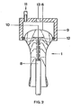
- a high voltage of approximately 20 kV is present between the heated lamp bulb 1 and the coating nozzle 8.
- the distribution of the layer densities and layer thicknesses is achieved by means of a cooling cap 9 and a circular, flat deflection plate 10.
- the piston tip 6 is cooled for about 10 s with blown air 11 of about 2.7 bar.
- the cooling cap 9 is placed on the lamp bulb 1, which extends down to the height of the largest bulb diameter and is sealed with a rubber ring 12.
- the blown air 11 escapes through an opening 13 made in the cooling cap 9.
- the deflection plate is arranged inside the lamp bulb 1 above and concentrically with the coating nozzle 8, likewise at about the height of the largest bulb diameter.
- the lamp bulb 1, which was heated to about 450 K before the start of siliconizing, is kept at a temperature of about 300 K during the siliconizing in the area of the bulb top 6, while the rest of the bulb part has about 420 K.
Landscapes
- Vessels And Coating Films For Discharge Lamps (AREA)
- Glass Compositions (AREA)
- Formation Of Various Coating Films On Cathode Ray Tubes And Lamps (AREA)
- Circuit Arrangement For Electric Light Sources In General (AREA)
Priority Applications (1)
| Application Number | Priority Date | Filing Date | Title |
|---|---|---|---|
| AT84113117T ATE35482T1 (de) | 1983-11-08 | 1984-10-31 | Verfahren zur herstellung einer elektrischen gluehlampe. |
Applications Claiming Priority (2)
| Application Number | Priority Date | Filing Date | Title |
|---|---|---|---|
| DE19833340387 DE3340387A1 (de) | 1983-11-08 | 1983-11-08 | Elektrische gluehlampe und verfahren zu deren herstellung |
| DE3340387 | 1983-11-08 |
Publications (3)
| Publication Number | Publication Date |
|---|---|
| EP0141402A2 true EP0141402A2 (fr) | 1985-05-15 |
| EP0141402A3 EP0141402A3 (en) | 1986-02-12 |
| EP0141402B1 EP0141402B1 (fr) | 1988-06-29 |
Family
ID=6213767
Family Applications (1)
| Application Number | Title | Priority Date | Filing Date |
|---|---|---|---|
| EP84113117A Expired EP0141402B1 (fr) | 1983-11-08 | 1984-10-31 | Méthode de fabrication d'une lampe électrique à incandescence |
Country Status (3)
| Country | Link |
|---|---|
| EP (1) | EP0141402B1 (fr) |
| AT (1) | ATE35482T1 (fr) |
| DE (2) | DE3340387A1 (fr) |
Cited By (2)
| Publication number | Priority date | Publication date | Assignee | Title |
|---|---|---|---|---|
| EP0237104A1 (fr) * | 1986-03-11 | 1987-09-16 | Koninklijke Philips Electronics N.V. | Ampoule de lampe soufflée et lampe électrique pourvue d'une telle ampoule |
| WO1991010256A1 (fr) * | 1989-12-22 | 1991-07-11 | Gte Products Corporation | Ampoule au tungstene-halogene dotee d'un reflecteur aluminise et procede de fabrication |
Family Cites Families (4)
| Publication number | Priority date | Publication date | Assignee | Title |
|---|---|---|---|---|
| US1999014A (en) * | 1931-01-21 | 1935-04-23 | Hygrade Sylvania Corp | Manufacture of incandescent electric lamps |
| US2449268A (en) * | 1947-05-29 | 1948-09-14 | Sylvania Electric Prod | Electric lamp |
| US4081709A (en) * | 1975-11-20 | 1978-03-28 | General Electric Company | Electrostatic coating of silica powders on incandescent bulbs |
| NL7905367A (nl) * | 1979-07-10 | 1981-01-13 | Philips Nv | Elektrische lamp met een ten dele verspiegeld lampvat. |
-
1983
- 1983-11-08 DE DE19833340387 patent/DE3340387A1/de not_active Withdrawn
-
1984
- 1984-10-31 AT AT84113117T patent/ATE35482T1/de not_active IP Right Cessation
- 1984-10-31 EP EP84113117A patent/EP0141402B1/fr not_active Expired
- 1984-10-31 DE DE8484113117T patent/DE3472497D1/de not_active Expired
Cited By (2)
| Publication number | Priority date | Publication date | Assignee | Title |
|---|---|---|---|---|
| EP0237104A1 (fr) * | 1986-03-11 | 1987-09-16 | Koninklijke Philips Electronics N.V. | Ampoule de lampe soufflée et lampe électrique pourvue d'une telle ampoule |
| WO1991010256A1 (fr) * | 1989-12-22 | 1991-07-11 | Gte Products Corporation | Ampoule au tungstene-halogene dotee d'un reflecteur aluminise et procede de fabrication |
Also Published As
| Publication number | Publication date |
|---|---|
| ATE35482T1 (de) | 1988-07-15 |
| EP0141402A3 (en) | 1986-02-12 |
| DE3472497D1 (en) | 1988-08-04 |
| DE3340387A1 (de) | 1985-05-15 |
| EP0141402B1 (fr) | 1988-06-29 |
Similar Documents
| Publication | Publication Date | Title |
|---|---|---|
| DE2916956A1 (de) | Lichtemittierende halbleitervorrichtung | |
| EP0015026B1 (fr) | Lampe à incandescense | |
| DE4132753C2 (de) | Farbkathodenstrahlröhre | |
| EP0141402B1 (fr) | Méthode de fabrication d'une lampe électrique à incandescence | |
| RU94002568A (ru) | Способ получения ультрадисперсной двуокиси кремния, устройство для его реализации и ультрадисперсная двуокись кремния | |
| DE2637754A1 (de) | Verfahren zur herstellung einer kathodenstrahlroehre mit einem inneren leitenden ueberzug, vorrichtung zum durchfuehren dieses verfahrens und durch dieses verfahren hergestellte roehre | |
| EP0230050B1 (fr) | Dispositif de revêtement d'une partie de la surface interne d'ampoules de lampe | |
| DE2158022C3 (de) | Abtaststiltspitze zum Herstellen eines Kontaktschlusses beim Aufprüfen elektrisch leitender Farbbereiche auf Papier | |
| DE3320919A1 (de) | Niederdruck-quecksilberdampfentladungslampe und verfahren zu ihrer herstellung | |
| DE1921944A1 (de) | Kathodenstrahlroehre | |
| EP0354620A1 (fr) | Lampe électrique avec revêtement absorbant la lumière | |
| DE1064698B (de) | Lichtstreuender UEberzug auf der Innenflaeche eines lichtdurchlaessigen Gluehlampenkolbens | |
| DE690736C (de) | Verfahren und Vorrichtung zur Herstellung elektrischer Glueh- oder Glimmlampen | |
| DE2512906A1 (de) | Verfahren zur fertigung einer bildwiedergaberoehre | |
| DE3300449A1 (de) | Verfahren zur herstellung einer elektrode fuer eine hochdruckgasentladungslampe | |
| DE639569C (de) | Wassergekuehlte, zerlegbare elektrische Entladungsroehre mit unmittelbarem Anschlussan eine Hochleistungspumpe | |
| DE3736922A1 (de) | Lichtstrahlen verschiedener farbe liefernde leuchtstofflampe | |
| DE68908338T2 (de) | Schattenmaskenröhre für die Bilderzeugung, insbesondere fürs Farbfernsehen. | |
| DE3773656D1 (de) | Verfahren zum herstellen einer elektronenstrahlroehre und nach diesem verfahren erhaltene elektronenstrahlroehre. | |
| DE2709789A1 (de) | Verfahren zum herstellen einer niederdruckgasentladungslampe | |
| DE690696C (de) | ltung von Spannungen | |
| DE3405067A1 (de) | Roentgenroehre | |
| DE1921944C (de) | Farbbild Kathodenstrahlrohre | |
| DE589789C (de) | Fluessigkeitszerstaeuber | |
| DE2542800C3 (de) | Xenonlampe |
Legal Events
| Date | Code | Title | Description |
|---|---|---|---|
| PUAI | Public reference made under article 153(3) epc to a published international application that has entered the european phase |
Free format text: ORIGINAL CODE: 0009012 |
|
| AK | Designated contracting states |
Designated state(s): AT DE FR GB IT |
|
| PUAL | Search report despatched |
Free format text: ORIGINAL CODE: 0009013 |
|
| AK | Designated contracting states |
Designated state(s): AT DE FR GB IT |
|
| 17P | Request for examination filed |
Effective date: 19860219 |
|
| 17Q | First examination report despatched |
Effective date: 19870421 |
|
| GRAA | (expected) grant |
Free format text: ORIGINAL CODE: 0009210 |
|
| AK | Designated contracting states |
Kind code of ref document: B1 Designated state(s): AT DE FR GB IT |
|
| REF | Corresponds to: |
Ref document number: 35482 Country of ref document: AT Date of ref document: 19880715 Kind code of ref document: T |
|
| GBT | Gb: translation of ep patent filed (gb section 77(6)(a)/1977) | ||
| REF | Corresponds to: |
Ref document number: 3472497 Country of ref document: DE Date of ref document: 19880804 |
|
| ET | Fr: translation filed | ||
| ITF | It: translation for a ep patent filed | ||
| PLBE | No opposition filed within time limit |
Free format text: ORIGINAL CODE: 0009261 |
|
| STAA | Information on the status of an ep patent application or granted ep patent |
Free format text: STATUS: NO OPPOSITION FILED WITHIN TIME LIMIT |
|
| 26N | No opposition filed | ||
| ITTA | It: last paid annual fee | ||
| PGFP | Annual fee paid to national office [announced via postgrant information from national office to epo] |
Ref country code: AT Payment date: 19950920 Year of fee payment: 12 |
|
| PG25 | Lapsed in a contracting state [announced via postgrant information from national office to epo] |
Ref country code: AT Effective date: 19961031 |
|
| REG | Reference to a national code |
Ref country code: GB Ref legal event code: IF02 |
|
| PGFP | Annual fee paid to national office [announced via postgrant information from national office to epo] |
Ref country code: GB Payment date: 20021010 Year of fee payment: 19 |
|
| PGFP | Annual fee paid to national office [announced via postgrant information from national office to epo] |
Ref country code: FR Payment date: 20021023 Year of fee payment: 19 |
|
| PGFP | Annual fee paid to national office [announced via postgrant information from national office to epo] |
Ref country code: DE Payment date: 20021216 Year of fee payment: 19 |
|
| PG25 | Lapsed in a contracting state [announced via postgrant information from national office to epo] |
Ref country code: GB Free format text: LAPSE BECAUSE OF NON-PAYMENT OF DUE FEES Effective date: 20031031 |
|
| PG25 | Lapsed in a contracting state [announced via postgrant information from national office to epo] |
Ref country code: DE Free format text: LAPSE BECAUSE OF NON-PAYMENT OF DUE FEES Effective date: 20040501 |
|
| GBPC | Gb: european patent ceased through non-payment of renewal fee |
Effective date: 20031031 |
|
| PG25 | Lapsed in a contracting state [announced via postgrant information from national office to epo] |
Ref country code: FR Free format text: LAPSE BECAUSE OF NON-PAYMENT OF DUE FEES Effective date: 20040630 |
|
| REG | Reference to a national code |
Ref country code: FR Ref legal event code: ST |