EP0141406A1 - Installation d'électro-déposition en continu - Google Patents
Installation d'électro-déposition en continu Download PDFInfo
- Publication number
- EP0141406A1 EP0141406A1 EP84113159A EP84113159A EP0141406A1 EP 0141406 A1 EP0141406 A1 EP 0141406A1 EP 84113159 A EP84113159 A EP 84113159A EP 84113159 A EP84113159 A EP 84113159A EP 0141406 A1 EP0141406 A1 EP 0141406A1
- Authority
- EP
- European Patent Office
- Prior art keywords
- barrel
- plant
- electroplating
- metal items
- metal
- Prior art date
- Legal status (The legal status is an assumption and is not a legal conclusion. Google has not performed a legal analysis and makes no representation as to the accuracy of the status listed.)
- Withdrawn
Links
- 238000009713 electroplating Methods 0.000 title claims abstract description 30
- 239000002184 metal Substances 0.000 claims abstract description 30
- 229910052751 metal Inorganic materials 0.000 claims abstract description 30
- 238000012545 processing Methods 0.000 claims abstract description 19
- 238000007747 plating Methods 0.000 claims abstract description 13
- 238000004040 coloring Methods 0.000 claims abstract description 4
- 239000006193 liquid solution Substances 0.000 claims abstract 2
- 239000000463 material Substances 0.000 claims description 20
- 239000007788 liquid Substances 0.000 claims description 14
- 238000011282 treatment Methods 0.000 claims description 13
- 238000011144 upstream manufacturing Methods 0.000 claims description 7
- 238000011068 loading method Methods 0.000 claims description 4
- 238000004891 communication Methods 0.000 claims description 3
- 230000002093 peripheral effect Effects 0.000 claims description 3
- 238000013508 migration Methods 0.000 claims description 2
- 230000005012 migration Effects 0.000 claims description 2
- 239000011244 liquid electrolyte Substances 0.000 claims 1
- 238000004140 cleaning Methods 0.000 description 7
- 238000005238 degreasing Methods 0.000 description 4
- 230000003472 neutralizing effect Effects 0.000 description 4
- 238000005192 partition Methods 0.000 description 4
- 238000000151 deposition Methods 0.000 description 3
- 230000008021 deposition Effects 0.000 description 3
- 230000009471 action Effects 0.000 description 2
- 238000001035 drying Methods 0.000 description 2
- 238000004070 electrodeposition Methods 0.000 description 2
- 239000003792 electrolyte Substances 0.000 description 2
- 239000007769 metal material Substances 0.000 description 2
- 238000000034 method Methods 0.000 description 2
- 238000005554 pickling Methods 0.000 description 2
- 239000004033 plastic Substances 0.000 description 2
- 229920003023 plastic Polymers 0.000 description 2
- 238000004064 recycling Methods 0.000 description 2
- 239000000243 solution Substances 0.000 description 2
- 239000002904 solvent Substances 0.000 description 2
- 239000000126 substance Substances 0.000 description 2
- 238000009210 therapy by ultrasound Methods 0.000 description 2
- RYGMFSIKBFXOCR-UHFFFAOYSA-N Copper Chemical compound [Cu] RYGMFSIKBFXOCR-UHFFFAOYSA-N 0.000 description 1
- 229910000831 Steel Inorganic materials 0.000 description 1
- 239000002253 acid Substances 0.000 description 1
- 239000003929 acidic solution Substances 0.000 description 1
- 150000007513 acids Chemical class 0.000 description 1
- 238000004026 adhesive bonding Methods 0.000 description 1
- 230000002411 adverse Effects 0.000 description 1
- 239000003795 chemical substances by application Substances 0.000 description 1
- 239000011248 coating agent Substances 0.000 description 1
- 238000000576 coating method Methods 0.000 description 1
- 230000002860 competitive effect Effects 0.000 description 1
- 229910052802 copper Inorganic materials 0.000 description 1
- 239000010949 copper Substances 0.000 description 1
- 230000003247 decreasing effect Effects 0.000 description 1
- 238000005237 degreasing agent Methods 0.000 description 1
- 238000009791 electrochemical migration reaction Methods 0.000 description 1
- 238000003912 environmental pollution Methods 0.000 description 1
- 230000002349 favourable effect Effects 0.000 description 1
- 238000005246 galvanizing Methods 0.000 description 1
- 239000007789 gas Substances 0.000 description 1
- 230000005484 gravity Effects 0.000 description 1
- 238000009434 installation Methods 0.000 description 1
- 238000012423 maintenance Methods 0.000 description 1
- 229910021645 metal ion Inorganic materials 0.000 description 1
- 150000002739 metals Chemical class 0.000 description 1
- 238000012986 modification Methods 0.000 description 1
- 230000004048 modification Effects 0.000 description 1
- 238000012544 monitoring process Methods 0.000 description 1
- 230000036961 partial effect Effects 0.000 description 1
- 238000002360 preparation method Methods 0.000 description 1
- 238000002203 pretreatment Methods 0.000 description 1
- 230000008569 process Effects 0.000 description 1
- QQONPFPTGQHPMA-UHFFFAOYSA-N propylene Natural products CC=C QQONPFPTGQHPMA-UHFFFAOYSA-N 0.000 description 1
- 125000004805 propylene group Chemical group [H]C([H])([H])C([H])([*:1])C([H])([H])[*:2] 0.000 description 1
- 238000005086 pumping Methods 0.000 description 1
- 238000000746 purification Methods 0.000 description 1
- 230000009467 reduction Effects 0.000 description 1
- 230000002829 reductive effect Effects 0.000 description 1
- 238000005096 rolling process Methods 0.000 description 1
- 239000010959 steel Substances 0.000 description 1
- 238000013022 venting Methods 0.000 description 1
- 238000003466 welding Methods 0.000 description 1
Images


Classifications
-
- B—PERFORMING OPERATIONS; TRANSPORTING
- B65—CONVEYING; PACKING; STORING; HANDLING THIN OR FILAMENTARY MATERIAL
- B65G—TRANSPORT OR STORAGE DEVICES, e.g. CONVEYORS FOR LOADING OR TIPPING, SHOP CONVEYOR SYSTEMS OR PNEUMATIC TUBE CONVEYORS
- B65G33/00—Screw or rotary spiral conveyors
- B65G33/08—Screw or rotary spiral conveyors for fluent solid materials
- B65G33/12—Screw or rotary spiral conveyors for fluent solid materials with screws formed by straight tubes or drums having internal threads, or by spiral or helical tubes
-
- B—PERFORMING OPERATIONS; TRANSPORTING
- B65—CONVEYING; PACKING; STORING; HANDLING THIN OR FILAMENTARY MATERIAL
- B65G—TRANSPORT OR STORAGE DEVICES, e.g. CONVEYORS FOR LOADING OR TIPPING, SHOP CONVEYOR SYSTEMS OR PNEUMATIC TUBE CONVEYORS
- B65G49/00—Conveying systems characterised by their application for specified purposes not otherwise provided for
- B65G49/02—Conveying systems characterised by their application for specified purposes not otherwise provided for for conveying workpieces through baths of liquid
- B65G49/04—Conveying systems characterised by their application for specified purposes not otherwise provided for for conveying workpieces through baths of liquid the workpieces being immersed and withdrawn by movement in a vertical direction
- B65G49/0409—Conveying systems characterised by their application for specified purposes not otherwise provided for for conveying workpieces through baths of liquid the workpieces being immersed and withdrawn by movement in a vertical direction specially adapted for workpieces of definite length
- B65G49/0413—Conveying systems characterised by their application for specified purposes not otherwise provided for for conveying workpieces through baths of liquid the workpieces being immersed and withdrawn by movement in a vertical direction specially adapted for workpieces of definite length arrangements for conveyance through the bath
- B65G49/0422—Conveying systems characterised by their application for specified purposes not otherwise provided for for conveying workpieces through baths of liquid the workpieces being immersed and withdrawn by movement in a vertical direction specially adapted for workpieces of definite length arrangements for conveyance through the bath screws
-
- C—CHEMISTRY; METALLURGY
- C25—ELECTROLYTIC OR ELECTROPHORETIC PROCESSES; APPARATUS THEREFOR
- C25D—PROCESSES FOR THE ELECTROLYTIC OR ELECTROPHORETIC PRODUCTION OF COATINGS; ELECTROFORMING; APPARATUS THEREFOR
- C25D17/00—Constructional parts, or assemblies thereof, of cells for electrolytic coating
- C25D17/16—Apparatus for electrolytic coating of small objects in bulk
- C25D17/22—Apparatus for electrolytic coating of small objects in bulk having open containers
-
- C—CHEMISTRY; METALLURGY
- C25—ELECTROLYTIC OR ELECTROPHORETIC PROCESSES; APPARATUS THEREFOR
- C25D—PROCESSES FOR THE ELECTROLYTIC OR ELECTROPHORETIC PRODUCTION OF COATINGS; ELECTROFORMING; APPARATUS THEREFOR
- C25D17/00—Constructional parts, or assemblies thereof, of cells for electrolytic coating
- C25D17/16—Apparatus for electrolytic coating of small objects in bulk
- C25D17/28—Apparatus for electrolytic coating of small objects in bulk with means for moving the objects individually through the apparatus during treatment
Definitions
- This invention relates to a continuous-cycle electroplating plant.
- Electroplating plants e.g. for small metal items, which include one or more lines of tanks designed to contain treatment liquids (such as solvents, dissolved acids, degreasing agents, neutralizing agents, and the like) and transversely arranged one after another between two slide guides, are known in the art.
- An overhead crane structure is usually mounted movable along the slide, guides to shift, immerse, lift and rotate in succession plurality of transportable tumblers (usually consisting of a plastics material, such as propylene) into and out of the tanks in accordance with a desired sequence of operation steps.
- a complete electroplating cycle requires one or more tanks specifically designed to be used for one of the following wet preparation or cleaning steps of the metal material to be treated, namely pre-degreasing, pickling, degreasing, and neutralizing, and one or more specific tanks for electroplating proper as well as one or more tank for passivating or coloring the electroplated material.
- Another object of this invention is that such an electroplating plant be suitable for fully automated operation, and accordingly for outdoor installation, at competitive costs.
- a further object of this invention is to make it possible for the material to be plated to be prepared or cleaned by ultrasonic treatment rather than by chemical methods.
- Still another object of the invention is that such an electroplating plant be relatively easy to produce and require minimum maintenance.
- a continuous-cycle electroplating plant for plating loose metal items
- the plant including a multiplicity of sequentially arranged processing units which comprise at least one pre-treating unit, at least one electroplating units and at least one passivating or coloring unit, and being characterized in that each processing unit has a barrel mounted for rotation on a support structure, a spiral rigid with, and extending along and around, the inner side wall of the barrel, thereby acting, in use, as a spiral conveyor for moving the metal items from an inlet end of the barrel to its outlet end, and treating means for processing the metal items while being moved in the barrel.
- an electroplating unit 1 comprises a horizontal tubular body or barrel 2 having an inlet end 3 and an outlet end 4.
- the inlet end 3 includes an end plate or base formed with a central opening 5 into which an outer flexible conduit 6 opens.
- the flexible conduit 6 is arranged to receive loose metal material to be plated from a chute 7 fixed to a supporting framework, not shown.
- the interior of the barrel 2 is provided with a partition wall 8 in the form of an uninterrupted spiral or helix which extends from the end 3 to the end 4.
- the latter tapers and has a central discharge opening 9 which is preferably identical and coaxial with the opening 5.
- the helix 8 centrally delimits an interrupted axial opening 8a ( Figure 4) approximately similar in size and coaxial with the openings 5 and 9.
- a plurality of longitudinal seats 10 (five in number, in the example shown), each comprising e.g. one half of a tube longitudinally split into two halves and attached, such as by welding or glueing, to the external surface of the barrel 2.
- the seats 10 can be made blind, whereas at the inlet end 3 they can be closed with a stopper ( Figure 3).
- Those areas of the tubular body 2 which are covered by the tubular seats 10 are formed with a plurality of perforations 11 so as to establish direct liquid communication between the barrel interior and the interior of the seats.
- An electrically conductive rod 12, e.g. of copper, is provided at the longitudinal wall sections of the body 2 between any-two successive seats 10.
- the rods 12 are electrically connected to a ring 13 which is electrically connected, e.g. by means of sliding contacts generally indicated at 14, to the negative pole of a d.c. current supply (not shown).
- a d.c. current supply (not shown).
- an electrically conductive bar (not shown) is provided, the bars in the various seats 10 being all electrically connected, such as through a ring (not shown) similar to the ring 13, to the positive pole of the d.c. current supply.
- the barrel 2 is rotatably supported, e.g. through bearing rings 15 which rest on small bearing rollers 16. At least some of the rollers 16 are driving rollers in that they are keyed to a drive shaft 17, which is in turn driven, in use, by a power drive unit (not shown), for example, including a geared motoro
- a galvanization electrolyte sufficient to fill the bottom portion of the barrel and, in any case, reaching a level not higher than that of the openings 5 and 9. It will be seen that, in use, metal items to be plated are fed into the barrel 2 through the chute 7 and the flexible hose 6. The material falls and is immersed in the liquid contained in the barrel. Owing to rotation of the barrel and the presence of the inner spiral or helix 8, the material is caused to move progressively along the drum bottom and is finally discharged through the opening 9. Along said path, the material is permanently held close to the plating metal which can be in the form of balls or bars housed in the various seats 10 and in electric contact with the positive pole of the current supply.
- the material to be plated is held adjacent to at least one of the seats 10, namely to that one which, at a given position of the rotating barrel, happens to be at the lowest level.
- Closeness to the anodic zone (plating metal) and to the cathodic zone (items being plated) is an important factor in view of obtaining a considerable reduction in electrodeposition times owing to the fact that all ionic migration paths are drastically shortened, which results in an increased hourly output of the plant or system.
- the provision of a short distance between plating metal and material being plated makes it possible to use of limited amounts of electrolyte in the barrel.
- the material being plated is continuously moved throughout the galvanic treatment, and thus its entire surface is exposed directly to the galvanizing action of the electrolytic bath.
- the bath itself (not shown in the drawings) is also constantly stirred owing both to the mechanical action of the spiral or helix 8 and to its being forced to cyclically flow through the perforations 11, to enter one or more seats 10 as they move downwards during the barrel rotation and its being gradually discharged from one or more seats 10 as they move upwards. All these favourable factors promote uniform electrodeposition of a plating coating onto the metal items being plated, and makes it possible to operate, in general, at a significantly reduced amperage in the d.c. current supply.
- the length of time the material to be plated remains in the barrel 2 will depend on, and will vary with, the speed of rotation of the drum and the pitch of the helix 8.
- the plant can also comprise units (not shown) for carrying out generally required pre-treatment operations, such as one or more cleaning, degreasing, pickling and neutralizing units, each having a barrel similar to barrel 2 and being provided with a respective helix 8 but having no seats 10, perforations 11, rods 12 and related electric connections.
- Such units are designed to contain a specific treatment liquid, loaded continuously or intermittently from their end 3 with loose metal items to be processed, which are then immersed in the treatment liquid, tumbled, moved by the helix 8 throughout the barrel and discharged at the outlet end 4 thereof.
- Cleaning barrels may be arranged one after another in mutual longitudinal alignment upstream of one or more electroplating barrels. Furthermore, the various barrels can be driven by the same source of motion provided for the electroplating barrel or barrels.
- a lifting apparatus 20 such that shown in Figures 5 and 6, can be provided in order to lift the metal items discharged from a barrel to a higher level to be fed to a successive processing unit.
- the lifting device 20 comprises a hollow cylindrical body or drum 21 having a multiplicity of inner peripheral segments 22 separated from each other by radially extending partitions 23.
- the cylindrical body 21 has a wide inlet opening 24, through which a loading chute 25 extends, and an outlet opening 26, through which the discharge end of a stationary hopper or chute 27 located inside the cylindrical body 21 projects.
- the cylindrical body 21 is mounted for rotation about its longitudinal horizontal axis on a suitable supporting structure (not shown).
- each electroplating barrel can be equipped with a set of safety valves (e.g. weight-operated valves) for venting gases released during the galvanic process.
- safety valves e.g. weight-operated valves
- pumping arrangements for recycling treatment liquids or electrolytic baths.
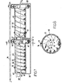
- the electroplating plant shown in Figures 7 and 8 comprises a plurality of sequentially arranged units each one including a tank 30 designed to contain a specific treatment liquid, such as a solvent, acidic solution, degreasing solution, or neutralizing solution.
- a specific treatment liquid such as a solvent, acidic solution, degreasing solution, or neutralizing solution.
- each tank 30 a respective conveying barrel or tumbler 40 has its sidewall formed with a plurality of small through holes 41.
- the various barrels 40 are axially aligned one with respect to the other and arranged in an orderly succession and partially immersed (e.g. by one third) in the treatment liquid contained in the underlying tank 30.
- Each barrel 40 has an upstream end 42 provided with an axial central inlet opening 43 and a downstream end 44 provided with an axial central outlet opening 45.
- annular enlarged portion or drum 46 having segments or compartments 47 delimited by radially extending shaped partitions 48.
- the drum 46 is similar in structure to the lifting apparatus 20.
- a spiral or helix 50 is provided along the inner wall of the barrels 40 and can have a pitch that can differ from one barrel to another.
- a discharge mouth 61 of a conveying and feed-in chute or hopper 60 extends through the inlet opening 43 at the upstream end 42 of each barrel.
- the feed-in hopper 60 for each barrel 40 arranged downstream of the first one is accommodated within the enlarged portion 46 of the immediately preceding barrel.
- Each barrel 40 is mounted for rotation, e.g. by means of suitable rolling supports not shown, on an encircling ring, generally indicated at 70, located in the vicinity of the upstream end 42, and on a ring 71 surrounding the enlarged portion 46.
- the ring 71 also supports a ring gear 72 which can mesh engage with a respective pinion gear 73 rigid in rotation with a drive shaft 74 common to all the barrels 40 and driven by a motor not shown.
- Each processing unit operates as follows. Loose metal items is fed by gravity through the hopper 60 upstream of a barrel 40, as the latter is being rotated, and moved forward by the spiral 50 towards the downstream end where it is discharged into the compartment 47 within the enlarged portion 46. While travelling through the barrel, the material is immersed in the treatment liquid which can readily enter the drum through the holes 6 1 formed in its walls. Once inside the enlarged portion 46, the treated material is lifted by the partitions 48 and discharged into the downstream hopper 40, to be transferred into the next barrel or removed from the plant.
- the residence time of the material being treated in the bath can be varied in many ways, such as, other things being equal, by chenging the barrel speed of rotation or the pitch of the respective spiral 50 or by providing barrels of different length for the various treatments.
- the tanks 30 will be equipped with the required accessories for supplying, recycling and draining the treatment baths.
- the electroplating tank(s) can be provided with suitable electric connections both for the material to be electroplated acting as the cathode and for the plating metal acting as the anode.
- a plant as described above can be operated in a continuous and fully automated fashion.
- the material to be plated is held at a short distance from the anode(s). Thus a reduce deposition time for the plating metal and a decreased amperage in the d.c. current supply are required, as mentioned above.
- One or more barrels 40 can be used in a drying unit, in which case, the tank 30 is replaced by a source of heat (such as streams of hot air) for drying the material inside the drum before being plated.
- a pre-treating processing barrel is made of metal, e.g. steel, cleaning of the items to be plated can include ultrasonic treatment.
- plastics materials are presently preferred as being adequately resistant to both chemical attack and wear.
Landscapes
- Chemical & Material Sciences (AREA)
- Engineering & Computer Science (AREA)
- Chemical Kinetics & Catalysis (AREA)
- Electrochemistry (AREA)
- Materials Engineering (AREA)
- Metallurgy (AREA)
- Organic Chemistry (AREA)
- Mechanical Engineering (AREA)
- Electroplating Methods And Accessories (AREA)
- Cleaning And De-Greasing Of Metallic Materials By Chemical Methods (AREA)
Applications Claiming Priority (4)
| Application Number | Priority Date | Filing Date | Title |
|---|---|---|---|
| IT8497483 | 1983-11-07 | ||
| IT8497583 | 1983-11-07 | ||
| IT84975/83A IT1181470B (it) | 1983-11-07 | 1983-11-07 | Impianto di elettroplaccatura a ciclo continuo |
| IT84974/83A IT1181469B (it) | 1983-11-07 | 1983-11-07 | Impianto di galvanostegia a ciclo continuo |
Publications (1)
| Publication Number | Publication Date |
|---|---|
| EP0141406A1 true EP0141406A1 (fr) | 1985-05-15 |
Family
ID=26330140
Family Applications (1)
| Application Number | Title | Priority Date | Filing Date |
|---|---|---|---|
| EP84113159A Withdrawn EP0141406A1 (fr) | 1983-11-07 | 1984-11-01 | Installation d'électro-déposition en continu |
Country Status (2)
| Country | Link |
|---|---|
| US (1) | US4559122A (fr) |
| EP (1) | EP0141406A1 (fr) |
Cited By (3)
| Publication number | Priority date | Publication date | Assignee | Title |
|---|---|---|---|---|
| WO1993017155A1 (fr) * | 1992-02-25 | 1993-09-02 | Ewald Dörken AG. | Dispositif pour l'enduction par electrolyse de petites pieces |
| DE10011865C1 (de) * | 2000-03-10 | 2001-06-07 | Wilms Gmbh | Einrichtung zur Beschichtung von Gegenständen, insbesondere Galvanisierung von Kleinteilen |
| DE102016209106A1 (de) | 2016-05-25 | 2017-11-30 | Schaeffler Technologies AG & Co. KG | Beschichtungsvorrichtung zur nasschemischen Beschichtung |
Families Citing this family (9)
| Publication number | Priority date | Publication date | Assignee | Title |
|---|---|---|---|---|
| US7344630B2 (en) * | 2006-04-12 | 2008-03-18 | Hsiue-Te Tu | Method and apparatus for electroplating small workpieces |
| KR100848514B1 (ko) | 2007-08-22 | 2008-07-25 | 김순호 | 스크루식 전착도장 장치 |
| WO2013074702A1 (fr) | 2011-11-15 | 2013-05-23 | Ashwin-Ushas Corporation, Inc. | Dispositif électrochromique à polymères complémentaires |
| US9207515B2 (en) | 2013-03-15 | 2015-12-08 | Ashwin-Ushas Corporation, Inc. | Variable-emittance electrochromic devices and methods of preparing the same |
| US9632059B2 (en) | 2015-09-03 | 2017-04-25 | Ashwin-Ushas Corporation, Inc. | Potentiostat/galvanostat with digital interface |
| US9482880B1 (en) | 2015-09-15 | 2016-11-01 | Ashwin-Ushas Corporation, Inc. | Electrochromic eyewear |
| US9945045B2 (en) | 2015-12-02 | 2018-04-17 | Ashwin-Ushas Corporation, Inc. | Electrochemical deposition apparatus and methods of using the same |
| US11352709B1 (en) | 2019-09-04 | 2022-06-07 | Presidio Components. Inc. | Helically ribbed electroplating barrel |
| CN112626595B (zh) * | 2020-12-01 | 2021-11-30 | 东莞市琢器机械设备科技有限公司 | 一种模组化连续电镀生产线 |
Citations (4)
| Publication number | Priority date | Publication date | Assignee | Title |
|---|---|---|---|---|
| FR844447A (fr) * | 1938-04-05 | 1939-07-25 | Perfectionnement aux appareils automatiques de traitements chimiques, électro-chimiques, et électrolytiques, pour petites pièces en masse | |
| US4062752A (en) * | 1976-10-04 | 1977-12-13 | Myron Lester Peterson | Plating mechanism |
| FR2446871A1 (fr) * | 1979-01-17 | 1980-08-14 | Rymland Robert | Appareil de traitement electrolytique et installation d'electrolyse mettant en oeuvre au moins un tel appareil |
| US4399828A (en) * | 1981-10-29 | 1983-08-23 | Kontos Nicholas G | Methods and apparatus for treating work pieces |
Family Cites Families (4)
| Publication number | Priority date | Publication date | Assignee | Title |
|---|---|---|---|---|
| US784034A (en) * | 1904-01-30 | 1905-03-07 | George W Clough | Electroplating device. |
| US1912400A (en) * | 1930-05-31 | 1933-06-06 | Mercil Plating Equipment Compa | Electroplating apparatus |
| NL62329C (fr) * | 1944-07-15 | |||
| DE3127390A1 (de) * | 1981-07-10 | 1983-02-10 | Siemens AG, 1000 Berlin und 8000 München | Galvanisiereinrichtung |
-
1984
- 1984-10-29 US US06/665,835 patent/US4559122A/en not_active Expired - Fee Related
- 1984-11-01 EP EP84113159A patent/EP0141406A1/fr not_active Withdrawn
Patent Citations (4)
| Publication number | Priority date | Publication date | Assignee | Title |
|---|---|---|---|---|
| FR844447A (fr) * | 1938-04-05 | 1939-07-25 | Perfectionnement aux appareils automatiques de traitements chimiques, électro-chimiques, et électrolytiques, pour petites pièces en masse | |
| US4062752A (en) * | 1976-10-04 | 1977-12-13 | Myron Lester Peterson | Plating mechanism |
| FR2446871A1 (fr) * | 1979-01-17 | 1980-08-14 | Rymland Robert | Appareil de traitement electrolytique et installation d'electrolyse mettant en oeuvre au moins un tel appareil |
| US4399828A (en) * | 1981-10-29 | 1983-08-23 | Kontos Nicholas G | Methods and apparatus for treating work pieces |
Cited By (5)
| Publication number | Priority date | Publication date | Assignee | Title |
|---|---|---|---|---|
| WO1993017155A1 (fr) * | 1992-02-25 | 1993-09-02 | Ewald Dörken AG. | Dispositif pour l'enduction par electrolyse de petites pieces |
| AU663924B2 (en) * | 1992-02-25 | 1995-10-26 | Ewald Dorken A.G. | The electrolytic coating of small parts |
| DE10011865C1 (de) * | 2000-03-10 | 2001-06-07 | Wilms Gmbh | Einrichtung zur Beschichtung von Gegenständen, insbesondere Galvanisierung von Kleinteilen |
| DE102016209106A1 (de) | 2016-05-25 | 2017-11-30 | Schaeffler Technologies AG & Co. KG | Beschichtungsvorrichtung zur nasschemischen Beschichtung |
| WO2017202403A1 (fr) | 2016-05-25 | 2017-11-30 | Schaeffler Technologies AG & Co. KG | Dispositif de revêtement servant au revêtement par voie chimique humide |
Also Published As
| Publication number | Publication date |
|---|---|
| US4559122A (en) | 1985-12-17 |
Similar Documents
| Publication | Publication Date | Title |
|---|---|---|
| US4559122A (en) | Continuous-cycle electroplating plant | |
| US3823074A (en) | Method for electroplating workpieces | |
| JP4982634B2 (ja) | 中空部品の表面を処理するための方法、このタイプの方法を実行するためのタンク、及びこの種のタンクを具備する表面を連続的に処理するための設備 | |
| RU2511732C2 (ru) | Установка для поверхностной обработки деталей | |
| EP0723604B1 (fr) | Procede et appareil pour le traitement de surface de pieces | |
| US4399828A (en) | Methods and apparatus for treating work pieces | |
| US5562810A (en) | Automated electrodeposition line | |
| FI70602C (fi) | Galvaniseringsanordning | |
| CS207361B2 (en) | Method of electrolytic dectinning of the tin refuse and device for making the same | |
| US2865831A (en) | Electroplating machine | |
| US3607712A (en) | Barrel-type processing apparatus | |
| US3898151A (en) | Apparatus for electrocoating conductive articles including magnet means to convey the articles | |
| EP0053676A1 (fr) | Dispositif pour le dépôt électrolytique de l'aluminium | |
| JPH08104999A (ja) | めっき用回転バレル装置とその使用方法 | |
| US6537430B1 (en) | System for galvanic treatment or finishing of pieces, and corresponding method | |
| US1744792A (en) | Electroplating apparatus | |
| US3647675A (en) | Automatic rotary electrodeposition apparatus | |
| EP0056844B1 (fr) | Dispositif pour le dépôt électrolytique de l'aluminium | |
| JP4391101B2 (ja) | 連続めっき装置 | |
| USRE19560E (en) | Electroprocessing machine | |
| JP2006257547A (ja) | 電着塗装装置、電着塗装方法、及び電着塗装システム | |
| HK1014563B (en) | Method and apparatus for the surface treatment of parts | |
| CN117535769A (zh) | 一种带肋钢筋电镀锌设备及生产线 | |
| CN117604599A (zh) | 一种带肋钢筋电镀锌生产线及工艺 | |
| DE3048511A1 (de) | Vorrichtung zum galvanischen abscheiden von aluminium |
Legal Events
| Date | Code | Title | Description |
|---|---|---|---|
| PUAI | Public reference made under article 153(3) epc to a published international application that has entered the european phase |
Free format text: ORIGINAL CODE: 0009012 |
|
| AK | Designated contracting states |
Designated state(s): AT CH DE FR GB LI |
|
| STAA | Information on the status of an ep patent application or granted ep patent |
Free format text: STATUS: THE APPLICATION IS DEEMED TO BE WITHDRAWN |
|
| 18D | Application deemed to be withdrawn |
Effective date: 19860116 |
|
| RIN1 | Information on inventor provided before grant (corrected) |
Inventor name: FOLCO, LUCIANO Inventor name: RENIERO, CIRILLO SILVANO |