EP0141493A2 - Flüssigkeitsprobeentnahmeventil für ein hydraulisches System - Google Patents
Flüssigkeitsprobeentnahmeventil für ein hydraulisches System Download PDFInfo
- Publication number
- EP0141493A2 EP0141493A2 EP84305475A EP84305475A EP0141493A2 EP 0141493 A2 EP0141493 A2 EP 0141493A2 EP 84305475 A EP84305475 A EP 84305475A EP 84305475 A EP84305475 A EP 84305475A EP 0141493 A2 EP0141493 A2 EP 0141493A2
- Authority
- EP
- European Patent Office
- Prior art keywords
- valve
- fluid
- flow
- valve assembly
- assembly according
- Prior art date
- Legal status (The legal status is an assumption and is not a legal conclusion. Google has not performed a legal analysis and makes no representation as to the accuracy of the status listed.)
- Withdrawn
Links
Images
Classifications
-
- G—PHYSICS
- G01—MEASURING; TESTING
- G01N—INVESTIGATING OR ANALYSING MATERIALS BY DETERMINING THEIR CHEMICAL OR PHYSICAL PROPERTIES
- G01N1/00—Sampling; Preparing specimens for investigation
- G01N1/02—Devices for withdrawing samples
- G01N1/10—Devices for withdrawing samples in the liquid or fluent state
- G01N1/20—Devices for withdrawing samples in the liquid or fluent state for flowing or falling materials
- G01N1/2035—Devices for withdrawing samples in the liquid or fluent state for flowing or falling materials by deviating part of a fluid stream, e.g. by drawing-off or tapping
-
- Y—GENERAL TAGGING OF NEW TECHNOLOGICAL DEVELOPMENTS; GENERAL TAGGING OF CROSS-SECTIONAL TECHNOLOGIES SPANNING OVER SEVERAL SECTIONS OF THE IPC; TECHNICAL SUBJECTS COVERED BY FORMER USPC CROSS-REFERENCE ART COLLECTIONS [XRACs] AND DIGESTS
- Y10—TECHNICAL SUBJECTS COVERED BY FORMER USPC
- Y10T—TECHNICAL SUBJECTS COVERED BY FORMER US CLASSIFICATION
- Y10T137/00—Fluid handling
- Y10T137/7722—Line condition change responsive valves
- Y10T137/7781—With separate connected fluid reactor surface
- Y10T137/7784—Responsive to change in rate of fluid flow
- Y10T137/7792—Movable deflector or choke
-
- Y—GENERAL TAGGING OF NEW TECHNOLOGICAL DEVELOPMENTS; GENERAL TAGGING OF CROSS-SECTIONAL TECHNOLOGIES SPANNING OVER SEVERAL SECTIONS OF THE IPC; TECHNICAL SUBJECTS COVERED BY FORMER USPC CROSS-REFERENCE ART COLLECTIONS [XRACs] AND DIGESTS
- Y10—TECHNICAL SUBJECTS COVERED BY FORMER USPC
- Y10T—TECHNICAL SUBJECTS COVERED BY FORMER US CLASSIFICATION
- Y10T137/00—Fluid handling
- Y10T137/8593—Systems
- Y10T137/87917—Flow path with serial valves and/or closures
- Y10T137/88046—Biased valve with external operator
Definitions
- the present invention relates to valve assemblies and, more particularly, to a valve assembly for use in sampling fluids.
- High pressure hydraulic systems experience failures as a result of abrasion and wear of critical component parts either due to the natural abrasion of high pressure high velocity fluid flow acting directly on the components or due to inter-component abrasion where moving parts operate in a high pressure environment. In either case, certain types of failure can be costly or even catastrophic if they are not detected in the incipient stage and no remedial action is taken.
- One method of detecting incipient failure is to obtain a sample of the hydraulic fluid from the operating system and analyse such sample for the presence of contaminants. For example, a pump in the system may be experiencing wear or erosion and metal from its parts is entering the fluid stream. Detection of such metal in the fluid sample would provide an indication and warning of the potential risk factor.
- Apparatus for monitoring the fluid in hydraulic systems where the pressure can reach as high as 42000 kN/ M 2 or 420 bar (about 6000 pounds per square inch gauge) or higher.
- Such apparatus makes use of a check-valve-controlled tap installed in the hydraulic system to which valve can be connected, by means of a suitable female coupling, a length of small bore flexible hose.
- the coupling for attaching the hose to the check-valve-controlled tap has a coaxial nipple that penetrates the check valve to unseat the latter upon tightening the female threaded coupling.
- a pressure gauge is connected to the free end of the hose and the arrangement is used for briefly observing the pressure at the site of the tap.
- a valve assembly for use in sampling fluids from high pressure hydraulic systems, said assembly comprising in combination a housing, a fluid flow passage through said housing from an inlet port to an outlet port, a nozzle being couplable to said outlet port, means for selectably starting and stopping the flow of fluid through said flow passage, means for limiting the flow velocity of said flow of fluid substantially independent of input fluid pressure, and means for diverting fluid from said outlet port to a vent port if fluid pressure at said outlet port exceeds a predetermined level.
- the means for diverting fluid from the outlet port to the vent port can advantageously comprise a spring biased pressure relief valve
- the flow velocity limiting means can advantageously comprise a spring biased regulator valve comprising for example a body disposed in said flow passage near the inlet port and having a cylindrical axial counterbore with side-wall ports, a valve spool disposed in said counterbore with a sliding fit and having a restricted orifice in a pressure head at its outer end and lateral apertures in its side wall, and a biasing spring within said counterbore for resisting inward movement of said valve spool.
- the means for selectably starting and stopping the flow of fluid through the flow passage conveniently might comprise a valve seat in said flow passage, a spring biased poppet valve disposed for movement in said housing into and out of flow occluding relationship with said valve seat, and a manually manipulable acuator member for unseating said poppet valve.
- the vent port opens into a cavity formed within the end of the housing surrounding the outlet port, said cavity being bounded by a skirt extending in the direction of the nozzle, and openings being provided in said skirt for the discharge of fluid passed by said diverting means when the housing is pressed against a membrane, such as the self-sealing diaphragm closing a sterile sampling bottle, which would otherwise seal off said cavity.
- the nozzle preferably has a membrane-piercing tip for introduction through such a sampling bottle diaphragm.
- Sampling of hydraulic fluid is accomplished by introducing a quantity of the fluid into a sampling bottle or similar container.
- a typical sample may range between 225 and 450 cc (about 8 and 16 fluid ounces) for example although the quantity is not critical nor a part of the present invention.
- the bottle is maintained in a sterile condition using techniques conventionally employed in biological sampling and is closed by a self-sealing diaphragm that can be penetrated by a small diameter tube, resembling a hypodermic needle but substantially larger in size, which diaphragm reseals itself upon withdrawal of the tube.
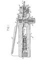
- the new valve assembly is shown as comprising a housing 10 having a main body portion 11 and a cap portion 12.
- a fluid flow passage 13 extends generally longitudinally through the housing 10 from an inlet port 14 in the main body portion 11 to an outlet port 15 in the cap portion 12.
- a nozzle 16 in the form of a small bore tube with a needle nose 17 at one end is coupled by a threaded coupling member 18 to the outlet port 15.
- a manually operable lever 19, pivotally joined at 20 to the body portion 11, bears upon an actuator member or pin 21 guided within an insert 22 that also serves to retain a washer 23 and O-ring seal 24 around the pin 21.
- the actuator pin 21 bears against a poppet valve 25 biased by a compression spring 26 into fluid sealing engagement with a valve seat 27.
- the seat 27 is disposed, as shown, within the flow passage 13.
- valve 28 comprises a body 29 disposed in the flow passage 13 near the inlet port 14.
- the body 29 has a cylindrical axial counterbore 30 with side-wall ports 31, e.g., six in number uniformly distributed circumferentially.
- a valve spool 32 is disposed in the counterbore 30 with a sliding fit and has a restricted orifice 33 in a pressure head 34 at its outer end and lateral apertures 35 in its side wall.
- a biasing spring 36 for resisting inward movement of the valve spool 32.
- the regulator valve 28 functions to restrict the fluid flow rate and is related to the dimensions of the passage 13 through the housing 10 so as to limit the flow velocity. While.from a consideration of safety one might consider reducing the flow velocity without limit, too low a velocity gives rise to a problem.
- the purpose of the sampling valve is to extract fluid so as to test for contaminants. However, if the velocity is too low the valve will behave as a filter permitting entrained particles to precipitate or settle out of the fluid, particularly where there are abrupt changes in direction within the fluid passages. As a consequence, while it does not represent a critical lower limit, it is presently contemplated to size the orifice 33 in regulator valve 28 relative to all the other parameters to limit the flow rate to about 0.68 litres per minute (0.18 US gallons per minute).
- passage 13 The dimensions of passage 13 are such that the maximum internal flow velocity for such flow rate is about 22 metres/sec. (72 ft./sec.). At the outlet tube or nozzle 16 the corresponding maximum flow velocity is about 2.2 m./sec. (7.2 ft./sec.), a fluid velocity that is well within the limits of that which is safe to handle and which cannot injure a human operator. Anything below about 3.0 to 4.5 m./sec. (10 to 15 ft./sec.) should be safe.
- the diverting means comprises a spring biased pressure relief valve 38 having a ball valve 39 cooperating with a valve seal 40 and regulated by a compression spring 41.
- relief valve 38 it is presently preferred to arrange for relief valve 38 to open at 210 kN/m 2 or 2.1 bar (about 30 p.s.i.g.) and to thereupon pass fluid to the vent port 37 which opens into a cavity 42 formed within the end of the housing 10 and, more specifically, in the end of the cap portion 12.
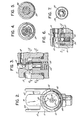
- the cavity 42 surrounds the outlet port 15 and is bounded by a skirt 43 extending in the direction of the nozzle 16.
- Openings 44 and 45 are provided in the skirt 43 for the discharge of fluid passed by the relief valve 38 when the housing 1.0 is pressed against a membrane that engages the skirt 43. Any discharge through openings 44 and 45 will be essentially harmless.
- the actuating lever 19 is located in a channel 46 between guard flanges 47 and 48 to reduce the risk of undesired or accidental manipulation of the lever.
- the flow regulator provides an adjustable orifice that closes as fluid pressure at inlet port 14 increases.
- the adjustable orifice is provided by the variable area overlap between the apertures 35 in the valve spool 32 and the side-wall ports 31 in the valve body 29. This arrangement regulates the flow rate in known manner.
Landscapes
- Life Sciences & Earth Sciences (AREA)
- Biochemistry (AREA)
- General Physics & Mathematics (AREA)
- Health & Medical Sciences (AREA)
- Chemical & Material Sciences (AREA)
- Analytical Chemistry (AREA)
- Hydrology & Water Resources (AREA)
- General Health & Medical Sciences (AREA)
- Physics & Mathematics (AREA)
- Immunology (AREA)
- Pathology (AREA)
- Safety Valves (AREA)
- Sampling And Sample Adjustment (AREA)
- Multiple-Way Valves (AREA)
- Preventing Unauthorised Actuation Of Valves (AREA)
Applications Claiming Priority (2)
| Application Number | Priority Date | Filing Date | Title |
|---|---|---|---|
| US539797 | 1983-10-07 | ||
| US06/539,797 US4537219A (en) | 1983-10-07 | 1983-10-07 | Fluid-sampling valve for a hydraulic system |
Publications (2)
| Publication Number | Publication Date |
|---|---|
| EP0141493A2 true EP0141493A2 (de) | 1985-05-15 |
| EP0141493A3 EP0141493A3 (de) | 1986-04-30 |
Family
ID=24152690
Family Applications (1)
| Application Number | Title | Priority Date | Filing Date |
|---|---|---|---|
| EP19840305475 Withdrawn EP0141493A3 (de) | 1983-10-07 | 1984-08-10 | Flüssigkeitsprobeentnahmeventil für ein hydraulisches System |
Country Status (5)
| Country | Link |
|---|---|
| US (1) | US4537219A (de) |
| EP (1) | EP0141493A3 (de) |
| JP (1) | JPS6097236A (de) |
| CA (1) | CA1215557A (de) |
| ES (1) | ES8506144A1 (de) |
Cited By (1)
| Publication number | Priority date | Publication date | Assignee | Title |
|---|---|---|---|---|
| CN107829905B (zh) * | 2017-09-26 | 2020-05-19 | 中国科学院理化技术研究所 | 高压充气阀体及高压充气系统 |
Families Citing this family (8)
| Publication number | Priority date | Publication date | Assignee | Title |
|---|---|---|---|---|
| US4919305A (en) * | 1987-11-06 | 1990-04-24 | Emco Wheaton, Inc. | Fuel dispensing nozzle with built-in flow regulator |
| DE19538281C1 (de) * | 1995-10-17 | 1996-10-24 | Paul Dipl Ing Appelhaus | Probenahmeventil zur Entnahme von flüssigen oder pastösen Proben aus einem Behälter oder Rohr |
| DE19853530C2 (de) * | 1998-11-20 | 2001-01-25 | Messer Griesheim Gmbh | Absperrvorrichtung für die Befülleinrichtung eines Druckbehälters |
| US9357749B2 (en) | 2010-01-29 | 2016-06-07 | Gea Houle Inc. | Rotary milking station, kit for assembling the same, and methods of assembling and operating associated thereto |
| US8381769B2 (en) * | 2010-03-29 | 2013-02-26 | Yuan Pin Industrial Co., Ltd. | Flow controller |
| CN102392903B (zh) * | 2011-09-28 | 2013-03-20 | 捷锐企业(上海)有限公司 | 一种气体行程开关阀 |
| US20160033051A1 (en) * | 2014-07-31 | 2016-02-04 | Parker-Hannifin Corporation | Shutoff valve assembly |
| CN104500755A (zh) * | 2014-12-09 | 2015-04-08 | 重庆迪科汽车研究有限公司 | 切削液紧急泄压阀 |
Family Cites Families (13)
| Publication number | Priority date | Publication date | Assignee | Title |
|---|---|---|---|---|
| US23487A (en) * | 1859-04-05 | Island | ||
| USRE23487E (en) | 1952-04-29 | Fill and discharge valve for lique | ||
| US1860046A (en) * | 1928-10-20 | 1932-05-24 | James D Mccutcheon | Cutting torch |
| US2388026A (en) * | 1942-05-18 | 1945-10-30 | Knapp Monarch Co | Dispensing faucet |
| US2548352A (en) * | 1949-01-29 | 1951-04-10 | Weatherhead Co | Combined filling and dispensing valve for volatile liquids |
| US2877796A (en) * | 1955-11-29 | 1959-03-17 | Joseph T Abdo | Combination pressure regulator and shut-off valve |
| US3015341A (en) * | 1958-01-10 | 1962-01-02 | William Waterman | Flow regulators |
| US3319648A (en) * | 1965-04-27 | 1967-05-16 | Deltrol Corp | Pressure-compensated flow control valves |
| US3319717A (en) * | 1965-10-04 | 1967-05-16 | Baker Oil Tools Inc | Multiple zone injection apparatus for well bores |
| US3502111A (en) * | 1965-10-14 | 1970-03-24 | Hansen Mfg | Dispensing device |
| US3863673A (en) * | 1973-04-11 | 1975-02-04 | Robert E Sitton | Container dispenser valve |
| NL7601131A (nl) * | 1975-03-07 | 1976-09-09 | Cornelius App | Tapkraan. |
| SE402812B (sv) * | 1975-07-11 | 1978-07-17 | Atlas Copco Ab | Tryckstyrd ventil for automatisk blockering av en pneumatisk krets |
-
1983
- 1983-10-07 US US06/539,797 patent/US4537219A/en not_active Expired - Fee Related
-
1984
- 1984-08-10 EP EP19840305475 patent/EP0141493A3/de not_active Withdrawn
- 1984-08-13 ES ES535118A patent/ES8506144A1/es not_active Expired
- 1984-09-17 CA CA000463273A patent/CA1215557A/en not_active Expired
- 1984-10-05 JP JP59208419A patent/JPS6097236A/ja active Pending
Cited By (1)
| Publication number | Priority date | Publication date | Assignee | Title |
|---|---|---|---|---|
| CN107829905B (zh) * | 2017-09-26 | 2020-05-19 | 中国科学院理化技术研究所 | 高压充气阀体及高压充气系统 |
Also Published As
| Publication number | Publication date |
|---|---|
| JPS6097236A (ja) | 1985-05-31 |
| ES535118A0 (es) | 1985-06-16 |
| EP0141493A3 (de) | 1986-04-30 |
| CA1215557A (en) | 1986-12-23 |
| ES8506144A1 (es) | 1985-06-16 |
| US4537219A (en) | 1985-08-27 |
Similar Documents
| Publication | Publication Date | Title |
|---|---|---|
| US4537219A (en) | Fluid-sampling valve for a hydraulic system | |
| DE69525070T2 (de) | "Onboard"-Dampfverwertungssystem mit zweistufigem Ventil | |
| CA1290588C (en) | Testing device for pilot valves | |
| US4240463A (en) | Safety valve actuator and pilot system | |
| US5623958A (en) | Low pressure relief valve | |
| US4391289A (en) | Check valve for rod out | |
| US4343337A (en) | Fuel dispensing nozzle | |
| DE20303617U1 (de) | Vorrichtung zur Atemalkoholmessung | |
| US3477456A (en) | Valve | |
| US4921008A (en) | Automatic fluid flow shutoff device | |
| US4004610A (en) | Line control | |
| US4480660A (en) | Safety valve | |
| DE102006048976A1 (de) | Feuchtigkeitsdetektionsanordnung | |
| US5107679A (en) | Safety valve for discharge chutes on cement mixer | |
| US4109714A (en) | Shutdown system for high pressure well | |
| DE4012801A1 (de) | Sicherheitsabsperrventil | |
| US8387618B2 (en) | Oxygen emergency supply device | |
| US3878862A (en) | Pneumatic valve position indicator | |
| US6279594B1 (en) | Flow actuated valve | |
| US5063960A (en) | Safety cartridge for compressed or liquefied gas | |
| US4192342A (en) | Rod out valve | |
| JPS61251745A (ja) | 流体試料採取弁 | |
| US4120315A (en) | Velocity check valve | |
| US3531981A (en) | Test apparatus to detect restriction in the brake pipe of railway brake systems | |
| US4176679A (en) | Check valve |
Legal Events
| Date | Code | Title | Description |
|---|---|---|---|
| PUAI | Public reference made under article 153(3) epc to a published international application that has entered the european phase |
Free format text: ORIGINAL CODE: 0009012 |
|
| AK | Designated contracting states |
Designated state(s): BE CH DE FR GB LI |
|
| PUAL | Search report despatched |
Free format text: ORIGINAL CODE: 0009013 |
|
| AK | Designated contracting states |
Kind code of ref document: A3 Designated state(s): BE CH DE FR GB LI |
|
| RHK1 | Main classification (correction) |
Ipc: F16K 17/168 |
|
| 17P | Request for examination filed |
Effective date: 19861018 |
|
| 17Q | First examination report despatched |
Effective date: 19880122 |
|
| STAA | Information on the status of an ep patent application or granted ep patent |
Free format text: STATUS: THE APPLICATION IS DEEMED TO BE WITHDRAWN |
|
| 18D | Application deemed to be withdrawn |
Effective date: 19880301 |
|
| RIN1 | Information on inventor provided before grant (corrected) |
Inventor name: MILISH, WILLIAM P. |