EP0141673B1 - Filterung elektrischer Signale - Google Patents
Filterung elektrischer Signale Download PDFInfo
- Publication number
- EP0141673B1 EP0141673B1 EP84307661A EP84307661A EP0141673B1 EP 0141673 B1 EP0141673 B1 EP 0141673B1 EP 84307661 A EP84307661 A EP 84307661A EP 84307661 A EP84307661 A EP 84307661A EP 0141673 B1 EP0141673 B1 EP 0141673B1
- Authority
- EP
- European Patent Office
- Prior art keywords
- loop
- neutral
- cable
- cables
- filter
- Prior art date
- Legal status (The legal status is an assumption and is not a legal conclusion. Google has not performed a legal analysis and makes no representation as to the accuracy of the status listed.)
- Expired
Links
- 238000001914 filtration Methods 0.000 title abstract description 3
- 230000007935 neutral effect Effects 0.000 claims abstract description 37
- 229910000859 α-Fe Inorganic materials 0.000 claims abstract description 19
- 239000003990 capacitor Substances 0.000 claims abstract description 13
- 230000008878 coupling Effects 0.000 claims description 3
- 238000010168 coupling process Methods 0.000 claims description 3
- 238000005859 coupling reaction Methods 0.000 claims description 3
- 239000000463 material Substances 0.000 claims description 3
- VAMFXQBUQXONLZ-UHFFFAOYSA-N icos-1-ene Chemical compound CCCCCCCCCCCCCCCCCCC=C VAMFXQBUQXONLZ-UHFFFAOYSA-N 0.000 claims 1
- 230000000694 effects Effects 0.000 abstract description 2
- 230000002452 interceptive effect Effects 0.000 description 3
- 230000003993 interaction Effects 0.000 description 2
- 238000010586 diagram Methods 0.000 description 1
- 230000004907 flux Effects 0.000 description 1
- 238000009413 insulation Methods 0.000 description 1
Images
Classifications
-
- H—ELECTRICITY
- H04—ELECTRIC COMMUNICATION TECHNIQUE
- H04B—TRANSMISSION
- H04B3/00—Line transmission systems
- H04B3/54—Systems for transmission via power distribution lines
- H04B3/56—Circuits for coupling, blocking, or by-passing of signals
-
- H—ELECTRICITY
- H04—ELECTRIC COMMUNICATION TECHNIQUE
- H04B—TRANSMISSION
- H04B2203/00—Indexing scheme relating to line transmission systems
- H04B2203/54—Aspects of powerline communications not already covered by H04B3/54 and its subgroups
- H04B2203/5462—Systems for power line communications
- H04B2203/5466—Systems for power line communications using three phases conductors
-
- H—ELECTRICITY
- H04—ELECTRIC COMMUNICATION TECHNIQUE
- H04B—TRANSMISSION
- H04B2203/00—Indexing scheme relating to line transmission systems
- H04B2203/54—Aspects of powerline communications not already covered by H04B3/54 and its subgroups
- H04B2203/5462—Systems for power line communications
- H04B2203/5483—Systems for power line communications using coupling circuits
- H04B2203/5487—Systems for power line communications using coupling circuits cables
-
- H—ELECTRICITY
- H04—ELECTRIC COMMUNICATION TECHNIQUE
- H04B—TRANSMISSION
- H04B2203/00—Indexing scheme relating to line transmission systems
- H04B2203/54—Aspects of powerline communications not already covered by H04B3/54 and its subgroups
- H04B2203/5462—Systems for power line communications
- H04B2203/5491—Systems for power line communications using filtering and bypassing
Definitions
- Electrical cables may carry AC currents of different frequencies. It is often desired to filter out currents of one band of frequencies while leaving substantially unaffected currents in another band of frequencies.
- Power cables within a building carry electrical currents at mains frequencies, e.g. normal AC currents at frequencies of 50 to 60 hertz and voltages of 100 to 500 volts. Higher or lower frequency currents (which may be termed "signals”) may be superimposed on normal or other AC currents.
- the same power cables within a given building may be used for carrying communication signals. Those signals are only wanted within the building, and should not travel to other buildings or to the central power station that supplies normal AC currents to the power cables, where the unwanted signals may cause interference.
- Power cables carrying a mains supply to a building carry high currents. It is dangerous to make connections and/or disconnections with the power cables while those high currents are flowing. But, it is not convenient to cut off the mains supply while such connections and/or disconnections are made.
- German patent specification DE-B-1 158 124 discloses an electrical filter suitable for application to electrical cables including a line cable, a neutral cable, and an earth cable, the filter comprising: a first loop, suitable for encircling the line and neutral cables but not the earth cable; and a second loop, encircled by said first loop, and comprising a capacitor.
- the present invention provides a power line communication system for electrical cables including a line cable, a neutral cable, and an earth cable, the system comprising at least one electrical filter, and characterised in that the filter comprises: a first loop (21), encircling the line and neutral cables but not the earth cable, and comprising ferrite material(s); and
- a second loop (22), being encircled by the first loop, the second loop comprising a capacitor (23), the inductance of the first loop being adapted for coupling the capacitor to the neutral cable, so as to form a parallel LC circuit in the neutral cable, the inductance and capacitance of the capacitor being chosen so that the parallel circuit has maximum impedance at the centre of a bandwidth of signals to be filtered out of said electrical cables.
- the present invention may be applied in any suitable environment, and embodied in any suitable manner.
- the first loop may be an assembly for being assembled around the line and neutral cables.
- the assembly may comprise pieces of ferrite material(s), e.g. a split ferrite core securely clamped in place. Ferrite loops are known for use in electrical filters but not for the present invention.
- the second loop may be disposed in any suitable manner.
- a said filter is coupled to a series resonance circuittuned to the frequency of signal(s) to be excluded, the series resonance circuit being coupled at its opposite ends respectively to the neutral cable and the earth cable.
- first and second said filters are disposed to form the cross arms of a T-filter, whose stem is formed by a said series resonance circuit.
- Said series resonance circuit may provide a sufficiently low impedance at the centre of said bandwidth so as to short circuit any signal(s) which may have passed through parallel circuit(s), e.g. from inside or outside a building.
- said electrical cables may be comprised by a 3-phase electrical distribution system.
- An advantage of connecting a communication system to the neutral and earth cables of a mains supply is that in a 3-phase electrical distribution system, the communication system may extend to all parts of a building to which any phase extends. In a communication system connected between the line and neutral cables, the coverage will only extend to the line cables of the one phase to which the system has been connected.
- the present invention may filter out communication signals from AC mains currents, e.g. normal AC currents in power cables.
- the present invention may be applied to any frequencies outside those used by an AC mains supply.
- the present invention may be applied to a bandwidth of signals in the range 20 to 500 kilohertz.
- a first said filter may be provided inside the building, and a second said filter may be provided outside the building.
- Those two filters may be the cross arms of a said T-filter, whose stem is a said series resonance circuit, tuned to the same communication frequency so as to provide a very low impedance at the centre of the band of communication frequencies which may have passed through parallel circuits either from inside or outside the building.
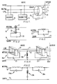
- the AC mains supply of a building comprises a line cable or wire 11, a neutral cable or wire 12, and an earth cable or wire 13.
- a communication system comprises a transmitter 14 connected between the neutral cable 12 and the earth cable 13.
- a plurality of receivers 15 (only one is shown) is also connected between the neutral cable 12 and the earth cable 13.
- the communication system operates at a very much higher frequency than the mains frequency, of the order of 100 kilohertz.
- a filter 20 is provided where the mains supply enters the building so as to stop communication frequency signals passing outside the building on the mains cables, and also to prevent spurious signals on the mains cables outside the building from interfering with the communication system in the building.
- Filter 20 comprises a ferrite loop 21, encircling the line cable 11 and the neutral cable 12. Ferrite loop 21 also encircles loop 22 containing a capacitor 23. Ferrite loop 21 may be made in two or more parts which are fitted together around the line and neutral cables 11,12 without the need to break those cables on assembly of filter 20. The earth cable 13 does not pass through ferrite loop 21. The line and neutral cables 11,12 pass through ferrite loop 21, whereas the neutral and earth cables 12,13 are used for the communication system in the present example.
- the equivalent circuit shows the interaction of neutral cable 12 and ferrite loop 21.
- the interaction is shown as a single turn 31 in the neutral cable 12 around a core 32 which transfers magnetic flux to a single turn in the loop 22 containing capacitor 23.
- the transformer ratio may be altered by providing more than one turn of loop 22 around ferrite loop 21.
- the equivalent circuit shows transformer coupling via ferrite loop 21 which brings capacitor 23 into a parallel resonance circuit L,C in neutral cable 12, the inductance L being of the ferrite loop 21, and the capacitance C being of capacitor 23.
- the values of the inductance and capacitance are chosen so that the centre of the band of communication frequencies is equal to 1/ 2 LC, wherein 1 is measured in Henrys, C is measured in farads, and frequency is measured in hertz (i.e. cycles per second).
- Filter 20 provides a high impedance at the communication frequency where the cables leave the building, whereas the impedance between the neutral and earth cables 12,13 without filter 20 is relatively low. Thus, communication signals are therefore restricted within the building.
- a second filter may be provided where the cables enter the building so as to prevent communication frequency signals entering the building.
- Fig. 4 shows two filters 20a according to Fig. 1, and in a T-filter arrangement whose arms respectively contain those filters, and whose stem is a series resonance circuit 20b having its opposite ends respectively connected to the neutral and earth cables 12,13.
- the series resonance circuit is tuned to the centre of the communication frequency band so as to absorb signals that may have passed through the filters 20a in either direction.
- the series resonance circuit may easily be connected without interfering with the mains supply, by piercing the insulation of the neutral cable 12 and connection to a suitable earth point.
- Fig. 5 shows the equivalent circuit of the T-filter arrangement.
- the series resonance circuit 20b has a ferrite core in its coil.
Landscapes
- Engineering & Computer Science (AREA)
- Power Engineering (AREA)
- Computer Networks & Wireless Communication (AREA)
- Signal Processing (AREA)
- Networks Using Active Elements (AREA)
- Filters And Equalizers (AREA)
- Cable Transmission Systems, Equalization Of Radio And Reduction Of Echo (AREA)
Claims (5)
Priority Applications (1)
| Application Number | Priority Date | Filing Date | Title |
|---|---|---|---|
| AT84307661T ATE38456T1 (de) | 1983-11-07 | 1984-11-06 | Filterung elektrischer signale. |
Applications Claiming Priority (2)
| Application Number | Priority Date | Filing Date | Title |
|---|---|---|---|
| GB08329692A GB2148643B (en) | 1983-11-07 | 1983-11-07 | Filtering electrical signals |
| GB8329692 | 1983-11-07 |
Publications (3)
| Publication Number | Publication Date |
|---|---|
| EP0141673A2 EP0141673A2 (de) | 1985-05-15 |
| EP0141673A3 EP0141673A3 (en) | 1985-07-10 |
| EP0141673B1 true EP0141673B1 (de) | 1988-11-02 |
Family
ID=10551374
Family Applications (1)
| Application Number | Title | Priority Date | Filing Date |
|---|---|---|---|
| EP84307661A Expired EP0141673B1 (de) | 1983-11-07 | 1984-11-06 | Filterung elektrischer Signale |
Country Status (4)
| Country | Link |
|---|---|
| EP (1) | EP0141673B1 (de) |
| AT (1) | ATE38456T1 (de) |
| DE (1) | DE3475037D1 (de) |
| GB (1) | GB2148643B (de) |
Cited By (1)
| Publication number | Priority date | Publication date | Assignee | Title |
|---|---|---|---|---|
| WO2008067657A1 (en) * | 2006-12-04 | 2008-06-12 | Corinex Communications Corporation | Method and system for communicating over neutral power lines |
Families Citing this family (42)
| Publication number | Priority date | Publication date | Assignee | Title |
|---|---|---|---|---|
| GB8628004D0 (en) * | 1986-11-22 | 1986-12-31 | Emlux Ltd | Filtering electrical signals |
| KR910001385B1 (ko) * | 1987-08-07 | 1991-03-04 | 미쓰이 세끼유 가가꾸 고오교오 가부시끼가이샤 | 신호변별기 및 신호변별 방법 |
| GB2224407A (en) * | 1988-10-28 | 1990-05-02 | David Michael Rusby | Reducing impedance of mains supply and mains filter |
| US4903006A (en) * | 1989-02-16 | 1990-02-20 | Thermo King Corporation | Power line communication system |
| GB8920261D0 (en) * | 1989-09-07 | 1989-10-18 | Verran Electronics Limited | Computer communications system |
| US5257006A (en) * | 1990-09-21 | 1993-10-26 | Echelon Corporation | Method and apparatus for power line communications |
| FR2682837B1 (fr) * | 1991-10-17 | 1994-01-07 | Electricite De France | Circuit separateur-coupleur directif pour courants porteurs a frequence moyenne sur ligne electrique a basse tension. |
| US6282405B1 (en) | 1992-10-22 | 2001-08-28 | Norweb Plc | Hybrid electricity and telecommunications distribution network |
| GB9222205D0 (en) * | 1992-10-22 | 1992-12-02 | Norweb Plc | Low voltage filter |
| US6144292A (en) * | 1992-10-22 | 2000-11-07 | Norweb Plc | Powerline communications network employing TDMA, FDMA and/or CDMA |
| GB9417359D0 (en) * | 1994-08-26 | 1994-10-19 | Norweb Plc | A power transmission network and filter therefor |
| DE19515668C2 (de) * | 1995-04-28 | 2000-11-30 | Daimler Chrysler Ag | Anordnung zur Verminderung von Störsignalen auf Leitungen in Kabelbündeln |
| GB9816953D0 (en) * | 1998-08-04 | 1998-09-30 | Nor Web Dpl Limited | Power networks |
| EP0981188A1 (de) * | 1998-08-17 | 2000-02-23 | Ascom Systec AG | Anordnung zur Uebermittlung von Nachrichten über ein Niederspannungs-Stromversorgungsnetz sowie Zwischenstück |
| DE19957621C2 (de) * | 1999-11-30 | 2001-11-29 | Schleifring Und Appbau Gmbh | Anordnung zur Übertragung elektrischer Signale zwischen bewegten Teilen mit verringerter Wegezahl |
| IL149673A0 (en) | 1999-12-08 | 2002-11-10 | Ascom Powerline Comm Ag | Assembly for transmitting information via a low-voltage power supply network |
| US7176786B2 (en) | 2000-01-20 | 2007-02-13 | Current Technologies, Llc | Method of isolating data in a power line communications network |
| IL150830A0 (en) | 2000-01-20 | 2003-02-12 | Current Tech Llc | Method of isolating data in a power line communication network |
| US6998962B2 (en) | 2000-04-14 | 2006-02-14 | Current Technologies, Llc | Power line communication apparatus and method of using the same |
| US7103240B2 (en) | 2001-02-14 | 2006-09-05 | Current Technologies, Llc | Method and apparatus for providing inductive coupling and decoupling of high-frequency, high-bandwidth data signals directly on and off of a high voltage power line |
| US6965302B2 (en) | 2000-04-14 | 2005-11-15 | Current Technologies, Llc | Power line communication system and method of using the same |
| US6980089B1 (en) | 2000-08-09 | 2005-12-27 | Current Technologies, Llc | Non-intrusive coupling to shielded power cable |
| DE10050476B4 (de) * | 2000-10-12 | 2005-03-31 | IAD Gesellschaft für Informatik, Automatisierung und Datenverarbeitung mbH | Vorrichtung zur Durchführung sowohl von Messungen als auch von Datenübertragung in elektrischen Energieverteilnetzen |
| EP1371219A4 (de) | 2001-02-14 | 2006-06-21 | Current Tech Llc | Datenkommunikation über eine stromversorgungsleitung |
| US7053756B2 (en) | 2001-12-21 | 2006-05-30 | Current Technologies, Llc | Facilitating communication of data signals on electric power systems |
| US7199699B1 (en) | 2002-02-19 | 2007-04-03 | Current Technologies, Llc | Facilitating communication with power line communication devices |
| US7102478B2 (en) | 2002-06-21 | 2006-09-05 | Current Technologies, Llc | Power line coupling device and method of using the same |
| US6982611B2 (en) | 2002-06-24 | 2006-01-03 | Current Technologies, Llc | Power line coupling device and method of using the same |
| US7132819B1 (en) | 2002-11-12 | 2006-11-07 | Current Technologies, Llc | Floating power supply and method of using the same |
| US7075414B2 (en) | 2003-05-13 | 2006-07-11 | Current Technologies, Llc | Device and method for communicating data signals through multiple power line conductors |
| US7064654B2 (en) | 2002-12-10 | 2006-06-20 | Current Technologies, Llc | Power line communication system and method of operating the same |
| US6980090B2 (en) | 2002-12-10 | 2005-12-27 | Current Technologies, Llc | Device and method for coupling with electrical distribution network infrastructure to provide communications |
| US6980091B2 (en) | 2002-12-10 | 2005-12-27 | Current Technologies, Llc | Power line communication system and method of operating the same |
| US6965303B2 (en) | 2002-12-10 | 2005-11-15 | Current Technologies, Llc | Power line communication system and method |
| US7046124B2 (en) | 2003-01-21 | 2006-05-16 | Current Technologies, Llc | Power line coupling device and method of using the same |
| US7308103B2 (en) | 2003-05-08 | 2007-12-11 | Current Technologies, Llc | Power line communication device and method of using the same |
| US7460467B1 (en) | 2003-07-23 | 2008-12-02 | Current Technologies, Llc | Voice-over-IP network test device and method |
| US7113134B1 (en) | 2004-03-12 | 2006-09-26 | Current Technologies, Llc | Transformer antenna device and method of using the same |
| US7714682B2 (en) | 2007-06-21 | 2010-05-11 | Current Technologies, Llc | Power line data signal attenuation device and method |
| SE536959C2 (sv) * | 2013-05-29 | 2014-11-11 | Qt Systems Ab | Metod och system för överföring av data via elnät |
| JP6405515B2 (ja) * | 2014-11-12 | 2018-10-17 | Necマグナスコミュニケーションズ株式会社 | 遠隔検針システム |
| JP6405516B2 (ja) * | 2014-11-21 | 2018-10-17 | Necマグナスコミュニケーションズ株式会社 | 電力線通信システム |
Family Cites Families (3)
| Publication number | Priority date | Publication date | Assignee | Title |
|---|---|---|---|---|
| DE1158124B (de) * | 1962-02-24 | 1963-11-28 | Sueddeutsche Telefon App Kabel | Sperrkreisanordnung fuer traegerfrequente Nachrichtenuebertragung |
| DE1955712A1 (de) * | 1969-11-05 | 1971-05-13 | Siemens Ag | Traegerfrequenzsperrung durch Ferritkoerper an elektrischen Leitungen |
| GB2091976B (en) * | 1980-12-12 | 1984-12-05 | Ecs Energy Conversation System | Electricity supply signalling |
-
1983
- 1983-11-07 GB GB08329692A patent/GB2148643B/en not_active Expired
-
1984
- 1984-11-06 AT AT84307661T patent/ATE38456T1/de not_active IP Right Cessation
- 1984-11-06 DE DE8484307661T patent/DE3475037D1/de not_active Expired
- 1984-11-06 EP EP84307661A patent/EP0141673B1/de not_active Expired
Cited By (1)
| Publication number | Priority date | Publication date | Assignee | Title |
|---|---|---|---|---|
| WO2008067657A1 (en) * | 2006-12-04 | 2008-06-12 | Corinex Communications Corporation | Method and system for communicating over neutral power lines |
Also Published As
| Publication number | Publication date |
|---|---|
| GB2148643B (en) | 1988-03-16 |
| EP0141673A2 (de) | 1985-05-15 |
| GB8329692D0 (en) | 1983-12-07 |
| GB2148643A (en) | 1985-05-30 |
| ATE38456T1 (de) | 1988-11-15 |
| DE3475037D1 (en) | 1988-12-08 |
| EP0141673A3 (en) | 1985-07-10 |
Similar Documents
| Publication | Publication Date | Title |
|---|---|---|
| EP0141673A2 (de) | Filterung elektrischer Signale | |
| US5933071A (en) | Electricity distribution and/or power transmission network and filter for telecommunication over power lines | |
| CA1177557A (en) | Power line communication over ground and neutral conductors of plural residential branch circuits | |
| US4264827A (en) | Current mode data or power bus | |
| FI942447A0 (fi) | Foerfarande foer eliminering av stoerningar i ett elkraftoeverfoeringsnaet samt koppling i ett elkraftoeverfoeringsnaet | |
| GB2198605A (en) | Filtering electrical signals | |
| DE10331744A1 (de) | Induktive Ankoppelschaltung und Verfahren zur Nachrichtenübertragung in elektrischen Energieverteilnetzen | |
| US4835516A (en) | Arrangement for introducing audio-frequency signals into a power supply line | |
| US20080185917A1 (en) | Selective phase coupler | |
| JP7228774B2 (ja) | 結合装置 | |
| JP2003069457A (ja) | 光伝送システムのための電力供給 | |
| JPS6358415B2 (de) | ||
| JPS61141215A (ja) | 電気信号用フイルタ | |
| JPH03296313A (ja) | 電力線搬送通信用の単相三線式ブロッキングフィルタ | |
| SU432683A1 (ru) | Совмещенная линия электроснабжения и управления | |
| JPS6253373U (de) | ||
| JP3001717B2 (ja) | 誘導通信線 | |
| SU746797A1 (ru) | Лини электропередачи | |
| JPS62111529A (ja) | 低圧配電線利用の信号伝送装置 | |
| JPS61233375A (ja) | 信号伝送方法 | |
| JPS6247220A (ja) | 配電線搬送方式 | |
| JPH04276996A (ja) | 電線路搬送制御方式 | |
| JPS60206328A (ja) | 高周波回路装置 | |
| JPS61127214A (ja) | 双方向分岐回路 | |
| JPS60121810A (ja) | 搬送式インタ−ホンの搬送周波数帯域の雑音防止フィルタ |
Legal Events
| Date | Code | Title | Description |
|---|---|---|---|
| PUAI | Public reference made under article 153(3) epc to a published international application that has entered the european phase |
Free format text: ORIGINAL CODE: 0009012 |
|
| PUAL | Search report despatched |
Free format text: ORIGINAL CODE: 0009013 |
|
| AK | Designated contracting states |
Designated state(s): AT BE CH DE FR IT LI LU NL SE |
|
| AK | Designated contracting states |
Designated state(s): AT BE CH DE FR IT LI LU NL SE |
|
| 17P | Request for examination filed |
Effective date: 19851230 |
|
| 17Q | First examination report despatched |
Effective date: 19870225 |
|
| GRAA | (expected) grant |
Free format text: ORIGINAL CODE: 0009210 |
|
| AK | Designated contracting states |
Kind code of ref document: B1 Designated state(s): AT BE CH DE FR IT LI LU NL SE |
|
| PG25 | Lapsed in a contracting state [announced via postgrant information from national office to epo] |
Ref country code: SE Effective date: 19881102 Ref country code: NL Effective date: 19881102 Ref country code: LI Effective date: 19881102 Ref country code: CH Effective date: 19881102 Ref country code: BE Effective date: 19881102 Ref country code: AT Effective date: 19881102 |
|
| REF | Corresponds to: |
Ref document number: 38456 Country of ref document: AT Date of ref document: 19881115 Kind code of ref document: T |
|
| PG25 | Lapsed in a contracting state [announced via postgrant information from national office to epo] |
Ref country code: LU Free format text: LAPSE BECAUSE OF NON-PAYMENT OF DUE FEES Effective date: 19881130 |
|
| REF | Corresponds to: |
Ref document number: 3475037 Country of ref document: DE Date of ref document: 19881208 |
|
| ITF | It: translation for a ep patent filed | ||
| ET | Fr: translation filed | ||
| REG | Reference to a national code |
Ref country code: CH Ref legal event code: PL |
|
| NLV1 | Nl: lapsed or annulled due to failure to fulfill the requirements of art. 29p and 29m of the patents act | ||
| PLBE | No opposition filed within time limit |
Free format text: ORIGINAL CODE: 0009261 |
|
| STAA | Information on the status of an ep patent application or granted ep patent |
Free format text: STATUS: NO OPPOSITION FILED WITHIN TIME LIMIT |
|
| 26N | No opposition filed | ||
| ITTA | It: last paid annual fee | ||
| ITPR | It: changes in ownership of a european patent |
Owner name: CESSIONE;THORN LIGHTING LIMITED |
|
| PGFP | Annual fee paid to national office [announced via postgrant information from national office to epo] |
Ref country code: FR Payment date: 19960827 Year of fee payment: 13 |
|
| PGFP | Annual fee paid to national office [announced via postgrant information from national office to epo] |
Ref country code: DE Payment date: 19970129 Year of fee payment: 13 |
|
| PG25 | Lapsed in a contracting state [announced via postgrant information from national office to epo] |
Ref country code: FR Free format text: THE PATENT HAS BEEN ANNULLED BY A DECISION OF A NATIONAL AUTHORITY Effective date: 19971130 |
|
| PG25 | Lapsed in a contracting state [announced via postgrant information from national office to epo] |
Ref country code: DE Free format text: LAPSE BECAUSE OF NON-PAYMENT OF DUE FEES Effective date: 19980801 |
|
| REG | Reference to a national code |
Ref country code: FR Ref legal event code: ST |