EP0141688B1 - Canne chauffante sans perte à la terre - Google Patents
Canne chauffante sans perte à la terre Download PDFInfo
- Publication number
- EP0141688B1 EP0141688B1 EP84401686A EP84401686A EP0141688B1 EP 0141688 B1 EP0141688 B1 EP 0141688B1 EP 84401686 A EP84401686 A EP 84401686A EP 84401686 A EP84401686 A EP 84401686A EP 0141688 B1 EP0141688 B1 EP 0141688B1
- Authority
- EP
- European Patent Office
- Prior art keywords
- electrical
- heating rod
- heating
- screen
- network
- Prior art date
- Legal status (The legal status is an assumption and is not a legal conclusion. Google has not performed a legal analysis and makes no representation as to the accuracy of the status listed.)
- Expired
Links
- 238000010438 heat treatment Methods 0.000 title claims description 30
- 229910052751 metal Inorganic materials 0.000 claims description 9
- 239000002184 metal Substances 0.000 claims description 9
- 239000004020 conductor Substances 0.000 claims description 5
- 230000007935 neutral effect Effects 0.000 claims description 5
- 230000000694 effects Effects 0.000 description 3
- 229910052582 BN Inorganic materials 0.000 description 2
- PZNSFCLAULLKQX-UHFFFAOYSA-N Boron nitride Chemical compound N#B PZNSFCLAULLKQX-UHFFFAOYSA-N 0.000 description 2
- CPLXHLVBOLITMK-UHFFFAOYSA-N Magnesium oxide Chemical compound [Mg]=O CPLXHLVBOLITMK-UHFFFAOYSA-N 0.000 description 2
- 239000011810 insulating material Substances 0.000 description 2
- 239000007788 liquid Substances 0.000 description 2
- 239000000843 powder Substances 0.000 description 2
- DGAQECJNVWCQMB-PUAWFVPOSA-M Ilexoside XXIX Chemical compound C[C@@H]1CC[C@@]2(CC[C@@]3(C(=CC[C@H]4[C@]3(CC[C@@H]5[C@@]4(CC[C@@H](C5(C)C)OS(=O)(=O)[O-])C)C)[C@@H]2[C@]1(C)O)C)C(=O)O[C@H]6[C@@H]([C@H]([C@@H]([C@H](O6)CO)O)O)O.[Na+] DGAQECJNVWCQMB-PUAWFVPOSA-M 0.000 description 1
- ZOKXTWBITQBERF-UHFFFAOYSA-N Molybdenum Chemical compound [Mo] ZOKXTWBITQBERF-UHFFFAOYSA-N 0.000 description 1
- 229910000691 Re alloy Inorganic materials 0.000 description 1
- 229910001080 W alloy Inorganic materials 0.000 description 1
- PNEYBMLMFCGWSK-UHFFFAOYSA-N aluminium oxide Inorganic materials [O-2].[O-2].[O-2].[Al+3].[Al+3] PNEYBMLMFCGWSK-UHFFFAOYSA-N 0.000 description 1
- 230000007797 corrosion Effects 0.000 description 1
- 238000005260 corrosion Methods 0.000 description 1
- 238000009413 insulation Methods 0.000 description 1
- 239000000395 magnesium oxide Substances 0.000 description 1
- 238000004519 manufacturing process Methods 0.000 description 1
- 239000000463 material Substances 0.000 description 1
- 229910052750 molybdenum Inorganic materials 0.000 description 1
- 239000011733 molybdenum Substances 0.000 description 1
- 239000000615 nonconductor Substances 0.000 description 1
- 239000003208 petroleum Substances 0.000 description 1
- WUAPFZMCVAUBPE-UHFFFAOYSA-N rhenium atom Chemical compound [Re] WUAPFZMCVAUBPE-UHFFFAOYSA-N 0.000 description 1
- 238000000926 separation method Methods 0.000 description 1
- 229910052708 sodium Inorganic materials 0.000 description 1
- 239000011734 sodium Substances 0.000 description 1
- 239000000126 substance Substances 0.000 description 1
- 229910052715 tantalum Inorganic materials 0.000 description 1
- GUVRBAGPIYLISA-UHFFFAOYSA-N tantalum atom Chemical compound [Ta] GUVRBAGPIYLISA-UHFFFAOYSA-N 0.000 description 1
- XLYOFNOQVPJJNP-UHFFFAOYSA-N water Substances O XLYOFNOQVPJJNP-UHFFFAOYSA-N 0.000 description 1
Images
Classifications
-
- G—PHYSICS
- G21—NUCLEAR PHYSICS; NUCLEAR ENGINEERING
- G21C—NUCLEAR REACTORS
- G21C17/00—Monitoring; Testing ; Maintaining
- G21C17/001—Mechanical simulators
-
- H—ELECTRICITY
- H05—ELECTRIC TECHNIQUES NOT OTHERWISE PROVIDED FOR
- H05B—ELECTRIC HEATING; ELECTRIC LIGHT SOURCES NOT OTHERWISE PROVIDED FOR; CIRCUIT ARRANGEMENTS FOR ELECTRIC LIGHT SOURCES, IN GENERAL
- H05B3/00—Ohmic-resistance heating
- H05B3/40—Heating elements having the shape of rods or tubes
- H05B3/42—Heating elements having the shape of rods or tubes non-flexible
- H05B3/48—Heating elements having the shape of rods or tubes non-flexible heating conductor embedded in insulating material
-
- Y—GENERAL TAGGING OF NEW TECHNOLOGICAL DEVELOPMENTS; GENERAL TAGGING OF CROSS-SECTIONAL TECHNOLOGIES SPANNING OVER SEVERAL SECTIONS OF THE IPC; TECHNICAL SUBJECTS COVERED BY FORMER USPC CROSS-REFERENCE ART COLLECTIONS [XRACs] AND DIGESTS
- Y02—TECHNOLOGIES OR APPLICATIONS FOR MITIGATION OR ADAPTATION AGAINST CLIMATE CHANGE
- Y02E—REDUCTION OF GREENHOUSE GAS [GHG] EMISSIONS, RELATED TO ENERGY GENERATION, TRANSMISSION OR DISTRIBUTION
- Y02E30/00—Energy generation of nuclear origin
- Y02E30/30—Nuclear fission reactors
Definitions
- the present invention relates to an improved heating rod, such as they are used in particular to simulate combustible needles of a nuclear reactor or in general an elongated body, in the shape of a needle, and releasing calories .
- Document DE-A-1 151 327 already discloses heating needles generally formed by means of one or more electrical wires insulated from one another by magnesia, alumina or boron nitride and surrounded by a sheath outside. Needles or heating rods have also been produced comprising a plurality of parallel electrical wires secured by two pieces of metallic ends and surrounded by a tubular sheath also metallic which keeps the electrical insulating material in the form of compacted powder around the resistant and heated electrical wires strictly speaking.
- Such heating needles were the subject, in particular, of French patent No. 1,543,327 filed on August 25, 1967 for "Heating needle" in the name of the ATOMIC ENERGY COMMISSION.
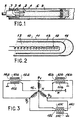
- Such a known needle is shown in FIG. 1 and consists of a set of resistant electrical wires such as 2 made of an alloy of tungsten and rhenium and previously shaped and cut to the desired length. These wires, nine in number in the embodiment considered, are arranged parallel to each other and for this purpose engaged in grooves 3 provided at the end of a cylindrical piece 4 of molybdenum terminated by a threaded end 5 allowing the needle to be connected to one of the poles of an appropriate electrical voltage source.
- the ends of the wires 2 once engaged in their grooves 3 are crimped to the press on the part 4 and introduced inside an outer tubular sheath 6 in tantalum. Is introduced inside the sheath and around the electrical wires 2 which it contains, an appropriate electrical insulating material 9 and more particularly boron nitride in powder or in preforms which is compacted as and when its introduction, either at the end of manufacture.
- the heating needle thus produced is connected by its threaded end 5 to a current source (not shown), the current output being effected by the other end of the sheath or by a separate conductor.
- a current source not shown
- Such a needle used to simulate the operation of a combustible needle in a reactor cooled by liquid sodium, plunges into the liquid bath through which the return of the current can possibly be carried out.
- heating rods constructed according to the previous model have the drawback of allowing, due to their external metallic sheath 6, electrical losses to the ground which, when used in conventional electrical distribution circuits, harm the protection of networks and personnel.
- the present invention specifically relates to a heating rod without loss to the ground which allows, using very simple means, to achieve the electrical protection of the internal heating element vis-à-vis the outside.
- This heating rod without loss to the ground which comprise, in a metallic envelope, an insulating medium, in which are embedded electrically resistant elements traversed by an electric current, an intermediate metallic screen with constant or zero potential between the resistant elements and the metal casing, is characterized in that the resistant elements being supplied by a three-phase electrical network, the intermediate metallic screen is connected to the neutral conductor (N) of the three-phase network.
- the intermediate metallic screen is connected in a very precise manner, it is thus possible to completely cancel the earth leakage current.
- the resistive elements of the heating rod being supplied by a three-phase electrical network
- the intermediate metallic screen is connected to the neutral conductor of the three-phase network.
- the intermediate metallic screen is connected at a precise point of the electrical supply network, independent of the earth, and where the currents of loss.
- the intermediate metallic screen can be of any known nature, in particular continuous metallic tube or lattice-shaped tube, as soon as it is located inside the insulation between the heating wire and the conductive outer sheath. Because this metal screen is brought to a constant potential (neutral at the precise point of a network independent of the earth) the external sheath cannot see any leakage of electric current. It can therefore therefore be connected to any metallic structure such as a tank or any other conducting environment, without there being any creation of circulation currents which can disturb the networks, cause electrical leaks and points of corrosion or risk to personnel.
- the heating rods according to the invention find a large number of applications, in particular in nuclear energy, where they can be used in reactor pressurizers of the pressurized water type as well as in the marine, on equipment on board at on the ships.
- the invention can be used in all applications where electrical losses to the ground are undesirable, as are any disturbances of electrical, electromagnetic or electrostatic origin.
- FIG 2 we see the end of a heating rod 10 having an outer casing 11 consisting of a conductive metal shield and the heating element 12 traversed by an electric current ensuring a release of calories by Joule effect.
- This heating element 12 is immersed in an electrical insulating medium 13 and, in accordance with the invention, an intermediate metal screen 14 electrically separates the interior of the cane speaking into two independent zones.
- the space between the screen 14 and the outer casing or shield 11 is also filled with an electrical insulator 15. Due to the electrical effect of the screen 14, the outer sheath or shield 11 sees no leakage electric coming from the heating element 12, as soon as the screen 14 is brought to a constant or zero potential.
- a thermal simulator comprising three insulating rods 10a, 10b and 10c, each provided with their electric screen 14a, 14b and 14c, as well as their heating elements 12a, 12b and 12c.
- the electrical supply of the three rods 10a, 10b and 10c, of their heating elements 12a, 12b and 12c is carried out using a three-phase network mounted in a star, each of the heating elements 12 being supplied between two of the consecutive phases ⁇ 1, ⁇ 2, ⁇ 3 of the three-phase system 16.
- the screens 14a, 14b and 14c are connected to the neutral point N of the three-phase network 16, which thus ensures the desired electrical protection effect.
- the shields or external armatures 11 a, 11 b and 11 of the three electric rods shown in FIG. 3 are simply earthed, which avoids any problem of potential difference with the environment (in particular tanks) in which the heating rods are used.
Landscapes
- Physics & Mathematics (AREA)
- Engineering & Computer Science (AREA)
- Plasma & Fusion (AREA)
- General Engineering & Computer Science (AREA)
- High Energy & Nuclear Physics (AREA)
- Resistance Heating (AREA)
- Control Of Resistance Heating (AREA)
Description
- La présente invention est relative à une canne chauffante perfectionnée, telle qu'on les utilise notamment pour simuler des aiguilles combustibles d'un réacteur nucléaire ou d'une façon générale un corps de forme allongée, en forme d'aiguille, et dégageant des calories.
- On connaît déjà par le document DE-A-1 151 327 des aiguilles chauffantes généralement constituées au moyen d'un ou plusieurs fils électriques isolés entre eux par de la magnésie, de l'alumine ou du nitrure de bore et entourées d'une gaine extérieure. On a également réalisé des aiguilles ou cannes chauffantes comportant une pluralité de fils électriques parallèles solidarisés par deux pièces d'extrémités métalliques et entourées par une gaine tubulaire également métallique qui maintient le matériau isolant électrique sous forme de poudre compactée autour des fils électriques résistants et chauffants à proprement parler. De telles aiguilles chauffantes ont fait l'objet notamment du brevet français n° 1 543 327 déposé le 25 août 1967 pour "Aiguille chauffante" au nom du COMMISSARIAT A L'ENERGIE ATOMIQUE.
- Une telle aiguille connue est représentée sur la fig. 1 et se compose d'un ensemble de fils électriques résistants tels que 2 réalisés en un alliage de tungstène et de rhénium et préalablement façonnés et coupés à la longueur désirée. Ces fils, au nombre de neuf dans l'exemple de réalisation considéré, sont disposés parallèlement les uns aux autres et à cet effet engagés dans des gorges 3 prévues à l'extrémité d'une pièce cylindrique 4 en molybdène terminée par un embout fileté 5 permettant de raccorder l'aiguille à un des pôles d'une source de tension électrique appropriée. Les extrémités des fils 2 une fois engagées dans leurs gorges 3 sont serties à la presse sur la pièce 4 et introduites à l'intérieur d'une gaine tubulaire extérieure 6 en tantale. On introduit à l'intérieur de la gaine et autour des fils électriques 2 qu'elle contient, un matériau isolant électrique approprié 9 et plus particulièrement du nitrure de bore en poudre ou en préformes que l'on compacte soit au fur et à mesure de son introduction, soit en fin de fabrication.
- En fonctionnement, l'aiguille chauffante ainsi réalisée est connectée par son embout fileté 5 à une source de courant (non représentée), la sortie du courant s'effectuant par l'autre extrémité de la gaine ou par un conducteur séparé. Une telle aiguille, utilisée pour simuler le fonctionnement d'une aiguille combustible dans un réacteur à refroidissement par sodium liquide, plonge dans le bain liquide par lequel peut éventuellement s'effectuer le retour du courant.
- Toutefois, des cannes chauffantes construites selon le modèle précédent présentent l'inconvénient de permettre, du fait de leur gaine métallique externe 6, des pertes électriques à la terre qui, lorsqu'on les emploie dans des circuits de distribution électriques classiques, nuisent à la protection des réseaux et du personnel.
- La présente invention a précisément pour objet une canne chauffante sans perte à la terre qui permet, à l'aide de moyens très simples, de réaliser la protection électrique de l'élément chauffant interne vis-à-vis de l'extérieur.
- Cette canne chauffante sans perte à la terre qui comportent, dans une enveloppe métallique, un milieu isolant, dans lequel sont noyés des éléments électriquement résistants parcourus par un courant électrique, un écran métallique intermédiaire à potentiel constant ou nul entre les éléments résistants et l'enveloppe métallique, se caractérise en ce que les éléments résistants étant alimentés par un réseau électrique triphasé, l'écran métallique intermédiaire est relié au conducteur neutre (N) du réseau triphasé.
- La présence d'un écran métallique intermédiaire, à potentiel constant ou nul, entre les éléments résistants chauffants et l'enveloppe métallique, permet d'obtenir une séparation électrique complète entre les conducteurs chauffants parcourus par le courant électrique et la gaine externe métallique en relation avec l'extérieur.
- A condition toutefois de réaliser le branchement de l'écran métallique intermédiaire de façon bien précise, on parvient ainsi à annuler complètement le courant de fuite à la terre.
- Dans un premier mode de mise en oeuvre de l'invention, les éléments résistants de la canne chauffante étant alimentés par un réseau électrique triphasé, l'écran métallique intermédiaire est relié au conducteur neutre du réseau triphasé.
- Dans un deuxième mode de mise en oeuvre de la canne chauffante, objet de l'invention, l'écran métallique intermédiaire est relié en un point précis du réseau électrique d'alimentation, indépendant de la terre, et où peuvent être collectés les courants de perte.
- Selon l'invention, l'écran métallique intermédiaire peut être de toute nature quelconque connue, notamment tube métallique continu ou tube en forme de treillis, dès lors qu'il se situe à l'intérieur de l'isolant entre le fil chauffant et la gaine extérieure conductrice. Du fait que cet écran métallique est porté à un potentiel constant (neutre au point précis d'un réseau indépendant de la terre) la gaine extérieure ne peut voir aucune fuite de courant électrique. Elle peut donc de ce fait être raccordée à toute structure métallique telle qu'une cuve ou tout autre environnement conducteur, sans qu'il y ait pour autant création de courants de circulation qui peuvent perturber les réseaux, provoquer des fuites électriques et des points de corrosion ou des risques pour le personnel.
- Les cannes chauffantes selon l'invention trouvent un grand nombre d'application, notamment dans l'énergie nucléaire, où l'on peut les utiliser dans les pressuriseurs de réacteur du type à eau pressurisée ainsi que dans la marine, sur du matériel embarqué à bord des bateaux. On peut également utiliser l'invention dans l'industrie chimique ou pétrolière où sont exigés des matériels anti-déflagrant. De manière générale, l'invention est utilisable dans toutes applications où les pertes électriques à la terre sont indésirables de même que toutes perturbations d'origine électrique, électromagnétique ou électrostatique.
- De toute façon, l'invention sera mieux comprise en se référant à la description qui suit d'un exemple de canne chauffante sans perte à la terre, description qui sera faite à titre surtout illustratif et non limitatif en se référant aux figures 2 et 3 ci-jointes, sur lesquelles:
- - la fig. 2 est une coupe schématique à travers une canne chauffante, objet de l'invention;
- - la fig. 3 représente le montage, dans un branchement sur un réseau triphasé, d'un simulateur thermique utilisant trois cannes chauffantes conformes à l'invention.
- Sur la figure 2, on voit l'extrémité d'une canne chauffante 10 comportant une enveloppe externe 11 constituée d'un blindage métallique conducteur et l'élément chauffant 12 parcouru par un courant électrique assurant un dégagement de calories par effet Joule. Cet élément chauffant 12 baigne dans un milieu isolant électrique 13 et conformément à l'invention, un écran métallique intermédiaire 14 sépare électriquement parlant l'intérieur de la canne en deux zones indépendantes. L'espace compris entre l'écran 14 et l'enveloppe ou blindage externe 11 est également rempli d'un isolant électrique 15. Du fait de l'effet électrique de l'écran 14, la gaine externe ou blindage 11 ne voit aucune fuite électrique en provenance de l'élément chauffant 12, dès lors que l'écran 14 est porté à un potentiel constant ou nul.
- Sur la fig. 3, on a représenté schématiquement le branchement possible d'un simulateur thermique comportant trois cannes isolantes 10a, 10b et 10c, munies chacune de leur écran électrique 14a, 14b et 14c, ainsi que de leurs éléments chauffants 12a, 12b et 12c.
- L'alimentation électrique des trois cannes 10a, 10b et 10c, de leurs éléments chauffants 12a, 12b et 12c est réalisée à l'aide d'un réseau triphasé monté en étoile, chacun des éléments chauffants 12 étant alimenté entre deux des phases consécutives Φ 1, Φ2, Φ3 du système triphasé 16.
- Conformément à l'invention, les écrans 14a, 14b et 14c sont reliés au point neutre N du réseau triphasé 16, ce qui assure ainsi l'effet électrique de protection recherché. Enfin, les blindages ou armatures externes 11 a, 11 b et 11 des trois cannes électriques représentées sur la fig. 3, sont simplement mises à la terre, ce qui évite tout problème de différence de potentiel avec l'environnement (cuves notamment) dans lequel sont employées les cannes chauffantes.
Claims (2)
Applications Claiming Priority (2)
| Application Number | Priority Date | Filing Date | Title |
|---|---|---|---|
| FR8313728A FR2551299B1 (fr) | 1983-08-25 | 1983-08-25 | Canne chauffante sans perte a la terre |
| FR8313728 | 1983-08-25 |
Publications (2)
| Publication Number | Publication Date |
|---|---|
| EP0141688A1 EP0141688A1 (fr) | 1985-05-15 |
| EP0141688B1 true EP0141688B1 (fr) | 1989-05-10 |
Family
ID=9291811
Family Applications (1)
| Application Number | Title | Priority Date | Filing Date |
|---|---|---|---|
| EP84401686A Expired EP0141688B1 (fr) | 1983-08-25 | 1984-08-17 | Canne chauffante sans perte à la terre |
Country Status (3)
| Country | Link |
|---|---|
| EP (1) | EP0141688B1 (fr) |
| DE (1) | DE3478186D1 (fr) |
| FR (1) | FR2551299B1 (fr) |
Families Citing this family (6)
| Publication number | Priority date | Publication date | Assignee | Title |
|---|---|---|---|---|
| FR2612723B1 (fr) * | 1987-03-19 | 1995-04-07 | Acim Jouanin | Cartouche electrique chauffante a double isolement et son procede de fabrication |
| FR2623043B3 (fr) * | 1987-11-05 | 1989-12-29 | Vulcanic | Dispositif de chauffage a resistance electrique isole |
| DE19519126A1 (de) * | 1995-05-16 | 1996-11-21 | Urs Dolder | Heizanordnung zur Erwärmung von diese umgebenden Medien |
| US9301341B2 (en) * | 2013-03-14 | 2016-03-29 | Chromalox, Inc. | Medium voltage heating element assembly |
| US20220111434A1 (en) | 2020-10-08 | 2022-04-14 | Wagstaff, Inc. | Material, apparatus, and method for refractory castings |
| US20240357712A1 (en) * | 2023-04-21 | 2024-10-24 | Wagstaff, Inc. | Material, apparatus, and method for electrically shielding heated components |
Family Cites Families (7)
| Publication number | Priority date | Publication date | Assignee | Title |
|---|---|---|---|---|
| DE1151327B (de) * | 1958-07-02 | 1963-07-11 | Licentia Gmbh | Elektrischer Hochspannungsheizstab |
| US3113244A (en) * | 1962-03-12 | 1963-12-03 | Gen Electric | Ground fault responsive protective system for electric power distribution apparatus |
| FR1368339A (fr) * | 1963-06-21 | 1964-07-31 | Soc Et Propulsion Par Reaction | Crayon chauffant |
| US3340382A (en) * | 1965-05-03 | 1967-09-05 | Arc O Vec Inc | Multi-cell electrical heater |
| GB1128819A (en) * | 1965-10-06 | 1968-10-02 | Atomic Energy Authority Uk | Improvements relating to immersion heaters for nuclear reactor pressurisers |
| DE2933376C2 (de) * | 1979-08-17 | 1983-02-10 | Hotset Heizpatronen und Zubehör GmbH, 5880 Lüdenscheid | Elektrischer Patronenheizkörper |
| US4326122A (en) * | 1980-07-14 | 1982-04-20 | The United States Of America As Represented By The United States Department Of Energy | Electric heater for nuclear fuel rod simulators |
-
1983
- 1983-08-25 FR FR8313728A patent/FR2551299B1/fr not_active Expired
-
1984
- 1984-08-17 EP EP84401686A patent/EP0141688B1/fr not_active Expired
- 1984-08-17 DE DE8484401686T patent/DE3478186D1/de not_active Expired
Also Published As
| Publication number | Publication date |
|---|---|
| FR2551299A1 (fr) | 1985-03-01 |
| EP0141688A1 (fr) | 1985-05-15 |
| DE3478186D1 (en) | 1989-06-15 |
| FR2551299B1 (fr) | 1985-10-11 |
Similar Documents
| Publication | Publication Date | Title |
|---|---|---|
| CA2138634C (fr) | Ligne a haute tension a isolation gazeuse pour longue distance | |
| FR2830272A1 (fr) | Dispositif de surveillance ou d'etude d'un reservoir traverse par un puits | |
| EP2523290B1 (fr) | Unité de terminaison pour câble supraconducteur multiphase | |
| EP0423665B1 (fr) | Ligne électrique blindée et son procédé de fabrication | |
| CN104466882B (zh) | 超导电缆接头 | |
| EP0005670B1 (fr) | Dispositif pour colmater une fuite dans une portion droite d'un tube d'échangeur de chaleur | |
| EP0141688A1 (fr) | Canne chauffante sans perte à la terre | |
| EP1681743A1 (fr) | Agencement de connexion des écrans de câbles supraconducteurs | |
| EP0573338A1 (fr) | Ligne blindée triphasée et son procédé de fabrication | |
| EP0314552B1 (fr) | Ensemble radiogène à protection intégrale contre les rayonnements de fuite | |
| CA1299241C (fr) | Resistance de freinage pour reseau electrique a haute tension | |
| FR2693129A1 (fr) | Outillage pour le traitement électrochimique de la surface interne d'un tube. | |
| FR2658972A1 (fr) | Dispositif de rechauffage de la colonne de production d'un puits et procede de mise en place des enroulements de rechauffage. | |
| EP0285464B1 (fr) | Dispositif de chauffage en particulier pour le traitement thermique d'un tube de petit diamètre et de forme courbe et utilisation de ce dispositif | |
| FR3097613B1 (fr) | Conduite sous-marine chauffante pour le transport de fluides et procédé d’assemblage d’une telle conduite | |
| EP1300913B1 (fr) | Connecteurs pour courants hautes tensions fonctionnant dans le vide | |
| BE353147A (fr) | Installation à rayons chi | |
| EP3996223B1 (fr) | Boîtier cryostat pour circuit câblé supraconducteur, et circuits câblés supraconducteurs associés | |
| FR2977396A1 (fr) | Ligne electrique munie de jonctions a arrets d'ecrans | |
| EP1037311B1 (fr) | Dispositif d'étanchéité d'une connexion de tresse plate | |
| FR2509080A1 (fr) | Liaison electrique pour longues distances | |
| FR2555372A1 (fr) | Jonction souple de raccordement de deux cables d'energie a haute tension | |
| FR2612723A1 (fr) | Cartouche electrique chauffante a double isolement et son procede de fabrication | |
| FR2747827A1 (fr) | Cable electrique a isolation gazeuse | |
| FR2576154A1 (fr) | Agencement de bus de type coaxial, notamment pour reseau local de communication |
Legal Events
| Date | Code | Title | Description |
|---|---|---|---|
| PUAI | Public reference made under article 153(3) epc to a published international application that has entered the european phase |
Free format text: ORIGINAL CODE: 0009012 |
|
| AK | Designated contracting states |
Designated state(s): BE DE GB IT SE |
|
| 17P | Request for examination filed |
Effective date: 19851011 |
|
| 17Q | First examination report despatched |
Effective date: 19870324 |
|
| RAP1 | Party data changed (applicant data changed or rights of an application transferred) |
Owner name: COMMISSARIAT A L'ENERGIE ATOMIQUE |
|
| GRAA | (expected) grant |
Free format text: ORIGINAL CODE: 0009210 |
|
| AK | Designated contracting states |
Kind code of ref document: B1 Designated state(s): BE DE GB IT SE |
|
| REF | Corresponds to: |
Ref document number: 3478186 Country of ref document: DE Date of ref document: 19890615 |
|
| RBV | Designated contracting states (corrected) |
Designated state(s): BE CH DE GB IT LI |
|
| ITF | It: translation for a ep patent filed | ||
| GBT | Gb: translation of ep patent filed (gb section 77(6)(a)/1977) | ||
| PLBE | No opposition filed within time limit |
Free format text: ORIGINAL CODE: 0009261 |
|
| STAA | Information on the status of an ep patent application or granted ep patent |
Free format text: STATUS: NO OPPOSITION FILED WITHIN TIME LIMIT |
|
| 26N | No opposition filed | ||
| PGFP | Annual fee paid to national office [announced via postgrant information from national office to epo] |
Ref country code: DE Payment date: 19900724 Year of fee payment: 7 |
|
| PGFP | Annual fee paid to national office [announced via postgrant information from national office to epo] |
Ref country code: BE Payment date: 19900803 Year of fee payment: 7 |
|
| PGFP | Annual fee paid to national office [announced via postgrant information from national office to epo] |
Ref country code: GB Payment date: 19900810 Year of fee payment: 7 |
|
| PGFP | Annual fee paid to national office [announced via postgrant information from national office to epo] |
Ref country code: CH Payment date: 19900821 Year of fee payment: 7 |
|
| ITTA | It: last paid annual fee | ||
| PG25 | Lapsed in a contracting state [announced via postgrant information from national office to epo] |
Ref country code: GB Effective date: 19910817 |
|
| PG25 | Lapsed in a contracting state [announced via postgrant information from national office to epo] |
Ref country code: LI Effective date: 19910831 Ref country code: CH Effective date: 19910831 Ref country code: BE Effective date: 19910831 |
|
| BERE | Be: lapsed |
Owner name: COMMISSARIAT A L'ENERGIE ATOMIQUE Effective date: 19910831 |
|
| GBPC | Gb: european patent ceased through non-payment of renewal fee | ||
| REG | Reference to a national code |
Ref country code: CH Ref legal event code: PL |
|
| PG25 | Lapsed in a contracting state [announced via postgrant information from national office to epo] |
Ref country code: DE Effective date: 19920501 |