EP0141708A2 - Führungsvorrichtung für die Betätigungsstange eines Hochspannungs-Leistungsschalters - Google Patents
Führungsvorrichtung für die Betätigungsstange eines Hochspannungs-Leistungsschalters Download PDFInfo
- Publication number
- EP0141708A2 EP0141708A2 EP84401969A EP84401969A EP0141708A2 EP 0141708 A2 EP0141708 A2 EP 0141708A2 EP 84401969 A EP84401969 A EP 84401969A EP 84401969 A EP84401969 A EP 84401969A EP 0141708 A2 EP0141708 A2 EP 0141708A2
- Authority
- EP
- European Patent Office
- Prior art keywords
- insulator
- ring
- elements
- guide
- control device
- Prior art date
- Legal status (The legal status is an assumption and is not a legal conclusion. Google has not performed a legal analysis and makes no representation as to the accuracy of the status listed.)
- Granted
Links
Images
Classifications
-
- H—ELECTRICITY
- H01—ELECTRIC ELEMENTS
- H01H—ELECTRIC SWITCHES; RELAYS; SELECTORS; EMERGENCY PROTECTIVE DEVICES
- H01H33/00—High-tension or heavy-current switches with arc-extinguishing or arc-preventing means
- H01H33/02—Details
- H01H33/42—Driving mechanisms
Definitions
- the invention relates to a device for controlling a high-voltage circuit breaker having an insulating operating rod extending coaxially with play inside a hollow support insulator made of several superimposed elements for transmitting the control movement.
- a motor mechanism from the area at ground potential to the area at high-voltage potential where the cut-off poles are arranged, in particular with arc self-blowing, said rod being slidably mounted and guided by at least one isolator guide extending in a transverse plane between the rod and the support insulator at the connection level of two successive elements of the support insulator.
- High voltage circuit breakers require significant control energy for the rapid displacement of the contacts and the compression of the dielectric blowing gas by the piston-cylinder assembly.
- This control energy is transmitted by a mechanical insulating rod connecting the high potential area to an area near the earth where the control mechanism is arranged, for example a hydraulic control.
- the pole (s), or breaking chambers, of the circuit breaker are carried by a column of support insulator whose height is appropriate to the voltage of the circuit breaker and which can reach several meters.
- the insulating rod is disposed inside this column of insulator-support which also constitutes a conduit for supplying dielectric gas to the breaking chambers. This insulating rod of great length is capable of transmitting significant tensile forces used to control the opening of the circuit breaker which requires the greatest energy.
- the closing maneuver controlled by a compression force of the control rod is limited by the risks of buckling of this rod.
- an intermediate piece is inserted between successive flange-like fittings.
- the object of the present invention is to remedy these drawbacks and to allow guiding of the control rod inside the support insulator by simple means tolerating large dispersions.
- the control device is characterized in that two superimposed elements of the porcelain support insulator are mechanically connected by butted fittings, sealed at the ends of said elements to form external connection flanges and by tightening bolts the pair of flanges butted and that an annular gap is formed between the opposite ends of said superimposed porcelain elements, in which gap are inserted an O-ring seal and the outer edge of the disc-shaped guide insulator.
- the fittings are placed against each other, while the outer edge of the disc-shaped guide insulator is simply interposed between the ends of the porcelain elements.
- a single O-ring seal is also inserted between these ends of the porcelain elements by externally surrounding the guide insulator, which simplifies the sealing problems and allows relatively large margins of spacing between the porcelains.
- the dispersions in the spacing between the porcelains and in the diameters of the molded part constituting the guide insulator which is a part coming from the foundry, are compensated by the elasticity of the O-ring.
- the guide insulator carries on its periphery bosses cooperating with the internal edge of the O-ring. These bosses provide gaps between the guide insulator and the O-ring available for compression of the latter.
- the housing of the O-ring is confined by the ends of the porcelain elements, by the guide insulator and on the opposite face by a metal ring whose outer edge cooperates with the fittings to ensure the centering of the latter.
- the guide insulator is advantageously a molded part made of epoxy resin, coming from the raw molding and carrying, in its central part a sleeve for guiding the control rod.
- This sleeve, in particular made of polytetrafluoroethylene is advantageously fixed by snap-fastening in a central orifice of the guide insulator, which avoids any machining of the latter.
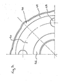
- the guide insulator has orifices for the passage of the gas contained inside the support insulator.
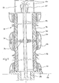
- a breaking chamber (10) of a high-voltage self-blowing circuit breaker is supported by a column of a support insulator (12) constituted by a superposition of two elements (14, 16) fixed on a base (18). placed on the ground.
- the support insulator (12) can very well carry two cut-off chambers (10) arranged in a V, each of these chambers having a pair of separable contacts (20) and a compression device with cylinder piston assembly (22), gas blowing, in this case sulfur hexafluoride contained in the chamber (10).
- the movable contact (20) is integral with a control rod (24) which extends coaxially inside the support insulator (12) of hollow cylindrical shape.
- the insulating control rod (24) is fixed at its lower part to a control mechanism constituted for example by a hydraulic cylinder (26) capable of controlling the opening and closing of the contacts (20) by translation of the rod (24 ).
- the support insulator (12) may include a superposition of a greater number of elements (14, 16), the height of the assembly possibly reaching several meters.
- the insulator (12) confines a sealed space filled with sulfur hexafluoride, this space advantageously being in communication with the breaking chamber (10).
- Each hollow cylindrical porcelain element (14, 16) carries at its ends fittings (28, 30) sealed by a cement (32).
- the flanged fittings (28, 30) are assembled by bolts (34).
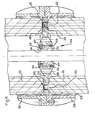
- the present invention relates more particularly to these intermediate pieces described in more detail below with reference to FIG. 2.
- the intermediate piece (36) is arranged in the joint zone of the superimposed elements (14, 16) extending in a transverse plane perpendicular to the rod (24).
- the flange-shaped fittings (28, 30) are placed one on top of the other, the assembly being arranged in such a way that the ends of the porcelain elements (14, 16) are spaced at (38) when the fittings (28, 30) are joined.
- the intermediate piece (36) constituted by a disc-shaped guide insulator (40) penetrates through its outer periphery (42) in the gap (38). In the interval (38) is also housed an elastic O-ring (44) which circumferentially surrounds the edge or periphery (42) of the disc (40).
- the O-ring (44) is in turn circumferentially surrounded by a metal ring (46) whose internal edge penetrates into the gap (38) and whose external edge cooperates with the fittings (28, 30) to ensure the centering of the overlapping fittings (28, 30).
- the disc (40) has openings (48) for passage of the gas contained in the support insulator (12) and a sleeve (50) for guiding the control rod (24).
- the elastic O-ring (44) inserted between the porcelain elements (14, 16) seals the junction between these elements (14, 16).
- the sleeve (50) for guiding the control rod (24) is snapped into the central hole of the disc (40).
- the sleeve (50) has two circular grooves (54, 56) each receiving a locking ring (58, 60), the ring (58) projecting permanently from the groove ( 54) while the ring (60) is arranged to be able come into a retracted position inside the groove (56).
- An elastic seal (62) biases the ring (60) in the projecting position.
- the edges of the central hole of the disc (40) have circular grooves (64,66) open respectively downwards and upwards. The fitting of the sleeve (50) takes place as follows.
- the sleeve (50) is slid from the bottom into the central opening of the disc (40) until the ring (60) coming opposite the groove upper (66) snaps into the latter.
- the ring (58) has come into abutment from the bottom of the groove (64) preventing any upward movement of the sleeve ( 50).
- This sleeve (50) is therefore retained on the disc (40) by simple snap-fastening, the grooves (64,66) possibly coming from molding and requiring no machining of the disc (40).
- the assembly is particularly simple and of easy assembly, the number of constituent parts of this assembly being limited.
- the manufacturing tolerances are compensated for by the elasticity of the O-ring (44), the mechanical connection between the superimposed elements (14, 16) being perfectly ensured by the fittings (28, 30) placed side by side.
- Guide insulators (40) can be inserted at each junction of superimposed elements (14, 16) or possibly only at some of these junctions when the risks of buckling are limited.
- the invention is of course in no way limited to the embodiment more particularly described and shown.
Landscapes
- Insulating Bodies (AREA)
- Driving Mechanisms And Operating Circuits Of Arc-Extinguishing High-Tension Switches (AREA)
- Circuit Breakers (AREA)
- Circuit Arrangements For Discharge Lamps (AREA)
- Generation Of Surge Voltage And Current (AREA)
- Insulators (AREA)
Priority Applications (1)
| Application Number | Priority Date | Filing Date | Title |
|---|---|---|---|
| AT84401969T ATE29336T1 (de) | 1983-10-24 | 1984-10-02 | Fuehrungsvorrichtung fuer die betaetigungsstange eines hochspannungs-leistungsschalters. |
Applications Claiming Priority (2)
| Application Number | Priority Date | Filing Date | Title |
|---|---|---|---|
| FR8317036A FR2553927B1 (fr) | 1983-10-24 | 1983-10-24 | Dispositif de guidage de la tige de commande d'un disjoncteur haute tension |
| FR8317036 | 1983-10-24 |
Publications (3)
| Publication Number | Publication Date |
|---|---|
| EP0141708A2 true EP0141708A2 (de) | 1985-05-15 |
| EP0141708A3 EP0141708A3 (en) | 1985-06-19 |
| EP0141708B1 EP0141708B1 (de) | 1987-09-02 |
Family
ID=9293528
Family Applications (1)
| Application Number | Title | Priority Date | Filing Date |
|---|---|---|---|
| EP84401969A Expired EP0141708B1 (de) | 1983-10-24 | 1984-10-02 | Führungsvorrichtung für die Betätigungsstange eines Hochspannungs-Leistungsschalters |
Country Status (5)
| Country | Link |
|---|---|
| US (1) | US4562321A (de) |
| EP (1) | EP0141708B1 (de) |
| AT (1) | ATE29336T1 (de) |
| DE (1) | DE3465825D1 (de) |
| FR (1) | FR2553927B1 (de) |
Cited By (1)
| Publication number | Priority date | Publication date | Assignee | Title |
|---|---|---|---|---|
| EP2246867A1 (de) * | 2009-04-29 | 2010-11-03 | ABB Technology AG | Halteklammer |
Families Citing this family (6)
| Publication number | Priority date | Publication date | Assignee | Title |
|---|---|---|---|---|
| US5483023A (en) * | 1994-03-22 | 1996-01-09 | General Electric Co. | High voltage bushing flange and flange to insulator joint |
| US6966125B2 (en) * | 2003-09-18 | 2005-11-22 | Shoot The Moon Products Ii, Llc | Automatic air movement for hair dryers |
| DE102010015729B4 (de) * | 2010-04-21 | 2015-01-22 | Maschinenfabrik Reinhausen Gmbh | Hochspannungsisolator |
| US8492656B2 (en) * | 2010-09-07 | 2013-07-23 | General Electric Company | High voltage bushing |
| CN104157474B (zh) * | 2014-09-01 | 2016-11-30 | 江苏神马电力股份有限公司 | 操纵杆及带有这种操纵杆的绝缘子 |
| CN108312087B (zh) * | 2017-12-29 | 2020-04-07 | 河南平高电气股份有限公司 | Gil支柱绝缘子试验用装配工装 |
Family Cites Families (8)
| Publication number | Priority date | Publication date | Assignee | Title |
|---|---|---|---|---|
| DE941069C (de) * | 1937-07-08 | 1956-04-05 | Siemens Ag | Loesbare Verbindung zweier Hochspannungsisolierkoerper |
| US2238567A (en) * | 1940-01-19 | 1941-04-15 | Gen Electric | Circuit breaker |
| FR2043902A5 (de) * | 1969-05-09 | 1971-02-19 | Merlin Gerin | |
| FR2272475B1 (de) * | 1974-05-20 | 1977-10-21 | Alsthom Cgee | |
| DE2851162A1 (de) * | 1978-11-25 | 1980-06-04 | Bbc Brown Boveri & Cie | Elektrischer leistungsschalter |
| FR2462012A1 (fr) * | 1979-07-16 | 1981-02-06 | Alsthom Cgee | Dispositif de manoeuvre d'un disjoncteur |
| ZA824849B (en) * | 1981-08-12 | 1983-11-30 | Northern Eng Ind | Circuit-breaker |
| GB2103881B (en) * | 1981-08-12 | 1984-11-28 | Northern Eng Ind | Circuit-breaker |
-
1983
- 1983-10-24 FR FR8317036A patent/FR2553927B1/fr not_active Expired
-
1984
- 1984-10-02 AT AT84401969T patent/ATE29336T1/de not_active IP Right Cessation
- 1984-10-02 DE DE8484401969T patent/DE3465825D1/de not_active Expired
- 1984-10-02 EP EP84401969A patent/EP0141708B1/de not_active Expired
- 1984-10-15 US US06/660,878 patent/US4562321A/en not_active Expired - Fee Related
Cited By (5)
| Publication number | Priority date | Publication date | Assignee | Title |
|---|---|---|---|---|
| EP2246867A1 (de) * | 2009-04-29 | 2010-11-03 | ABB Technology AG | Halteklammer |
| WO2010125005A1 (en) * | 2009-04-29 | 2010-11-04 | Abb Technology Ag | A support bracket |
| CN102414769A (zh) * | 2009-04-29 | 2012-04-11 | Abb技术有限公司 | 支撑托架 |
| US8455764B2 (en) | 2009-04-29 | 2013-06-04 | Abb Technology Ag | Support bracket |
| CN102414769B (zh) * | 2009-04-29 | 2015-02-25 | Abb技术有限公司 | 支撑托架 |
Also Published As
| Publication number | Publication date |
|---|---|
| EP0141708B1 (de) | 1987-09-02 |
| FR2553927A1 (fr) | 1985-04-26 |
| DE3465825D1 (en) | 1987-10-08 |
| FR2553927B1 (fr) | 1986-01-24 |
| US4562321A (en) | 1985-12-31 |
| EP0141708A3 (en) | 1985-06-19 |
| ATE29336T1 (de) | 1987-09-15 |
Similar Documents
| Publication | Publication Date | Title |
|---|---|---|
| EP0378950B1 (de) | Pol für selbstblasenden elektrischen Schalter | |
| EP0141708B1 (de) | Führungsvorrichtung für die Betätigungsstange eines Hochspannungs-Leistungsschalters | |
| FR2565037A1 (fr) | Connecteur electrique antideflagrant | |
| EP0239068A1 (de) | Druckgasschalter | |
| EP1111748B1 (de) | Verbindungssystem zwischen Mittel- oder Hochspannungszellen | |
| EP0908997B1 (de) | Abgedichtete Schutzvorrichtung für Hochspannungskabelverbindung | |
| WO2020099486A1 (fr) | Dispositif pyrotechnique avec boitier plastique | |
| FR2962252A1 (fr) | Chambre de coupure pour disjoncteur a moyenne ou haute tension a energie de manœuvre reduite | |
| EP3300196B1 (de) | Anschlusskammer mit höhenverstellbarem rahmen | |
| EP0171657B1 (de) | Ohne nennenswerten Gasverlust montierbarer und demontierbarer Druckgasschalter | |
| FR2577633A1 (fr) | Commande mecanique par cable a dispositif de reglage automatique et detecteur electrique de mise en oeuvre | |
| FR2814275A1 (fr) | Disjoncteur a isolation au gaz avec un transformateur de courant electronique integre | |
| FR2654545A1 (fr) | Dispositif de calage de la plaque superieure de support des guides de grappes par rapport a la cuve d'un reacteur nucleaire. | |
| FR2628258A1 (fr) | Interrupteur rotatif multipolaire a enveloppe etanche commune a tous les poles | |
| EP1714295A2 (de) | Einrichtung zum bewegen des steuerbalkens eines druckwasser-kernreaktors und verfahren zum anbringen der einrichtung an einer behälterabdeckung | |
| CA1273043A (fr) | Disjoncteur a haute tension a gaz dielectrique a resistance de fermeture | |
| EP1337018A1 (de) | Gasisolierte Stromdurchführung | |
| EP0350394B1 (de) | Regenwasserabflussanordnung | |
| FR2531257A1 (fr) | Element combustible de reacteur nucleaire | |
| FR2524701A1 (fr) | Disjoncteur blinde haute tension | |
| WO2011135037A1 (fr) | Traversee pour appareillage electrique sous enveloppe metallique et ensemble pour sectionneur de mise à la terre a maintien mecanique ameliore | |
| FR2797108A1 (fr) | Ligne electrique haute tension, a isolation gazeuse, module de raccordement entre troncons successifs constituant une telle ligne et procede de montage correspondant | |
| FR2528228A1 (fr) | Commutateur a came et a paquet protege contre les explosions et le grisou | |
| EP1274108A1 (de) | Ohne nennenswerten Gasverlust montierbarer und demontierbarer Druckgasschalterpol | |
| FR2854983A1 (fr) | Traversee de mouvement pour l'actionnement d'un appareillage de coupure en moyenne ou haute tension |
Legal Events
| Date | Code | Title | Description |
|---|---|---|---|
| PUAI | Public reference made under article 153(3) epc to a published international application that has entered the european phase |
Free format text: ORIGINAL CODE: 0009012 |
|
| PUAL | Search report despatched |
Free format text: ORIGINAL CODE: 0009013 |
|
| AK | Designated contracting states |
Designated state(s): AT BE CH DE GB IT LI NL SE |
|
| AK | Designated contracting states |
Designated state(s): AT BE CH DE GB IT LI NL SE |
|
| 17P | Request for examination filed |
Effective date: 19851024 |
|
| 17Q | First examination report despatched |
Effective date: 19861023 |
|
| ITF | It: translation for a ep patent filed | ||
| GRAA | (expected) grant |
Free format text: ORIGINAL CODE: 0009210 |
|
| AK | Designated contracting states |
Kind code of ref document: B1 Designated state(s): AT BE CH DE GB IT LI NL SE |
|
| REF | Corresponds to: |
Ref document number: 29336 Country of ref document: AT Date of ref document: 19870915 Kind code of ref document: T |
|
| REF | Corresponds to: |
Ref document number: 3465825 Country of ref document: DE Date of ref document: 19871008 |
|
| PGFP | Annual fee paid to national office [announced via postgrant information from national office to epo] |
Ref country code: NL Payment date: 19871031 Year of fee payment: 4 |
|
| GBT | Gb: translation of ep patent filed (gb section 77(6)(a)/1977) | ||
| PLBE | No opposition filed within time limit |
Free format text: ORIGINAL CODE: 0009261 |
|
| STAA | Information on the status of an ep patent application or granted ep patent |
Free format text: STATUS: NO OPPOSITION FILED WITHIN TIME LIMIT |
|
| 26N | No opposition filed | ||
| PG25 | Lapsed in a contracting state [announced via postgrant information from national office to epo] |
Ref country code: GB Effective date: 19881002 Ref country code: AT Effective date: 19881002 |
|
| PG25 | Lapsed in a contracting state [announced via postgrant information from national office to epo] |
Ref country code: SE Effective date: 19881003 |
|
| PG25 | Lapsed in a contracting state [announced via postgrant information from national office to epo] |
Ref country code: LI Effective date: 19881031 Ref country code: CH Effective date: 19881031 Ref country code: BE Effective date: 19881031 |
|
| BERE | Be: lapsed |
Owner name: MERLIN GERIN Effective date: 19881031 |
|
| PG25 | Lapsed in a contracting state [announced via postgrant information from national office to epo] |
Ref country code: NL Effective date: 19890501 |
|
| NLV4 | Nl: lapsed or anulled due to non-payment of the annual fee | ||
| REG | Reference to a national code |
Ref country code: CH Ref legal event code: PL |
|
| PG25 | Lapsed in a contracting state [announced via postgrant information from national office to epo] |
Ref country code: DE Effective date: 19890701 |
|
| GBPC | Gb: european patent ceased through non-payment of renewal fee | ||
| EUG | Se: european patent has lapsed |
Ref document number: 84401969.5 Effective date: 19890622 |