EP0141714A2 - Optischer Modulator - Google Patents
Optischer Modulator Download PDFInfo
- Publication number
- EP0141714A2 EP0141714A2 EP84402077A EP84402077A EP0141714A2 EP 0141714 A2 EP0141714 A2 EP 0141714A2 EP 84402077 A EP84402077 A EP 84402077A EP 84402077 A EP84402077 A EP 84402077A EP 0141714 A2 EP0141714 A2 EP 0141714A2
- Authority
- EP
- European Patent Office
- Prior art keywords
- cell
- cells
- capillary space
- optical modulator
- light beam
- Prior art date
- Legal status (The legal status is an assumption and is not a legal conclusion. Google has not performed a legal analysis and makes no representation as to the accuracy of the status listed.)
- Granted
Links
Images




Classifications
-
- G—PHYSICS
- G02—OPTICS
- G02B—OPTICAL ELEMENTS, SYSTEMS OR APPARATUS
- G02B5/00—Optical elements other than lenses
- G02B5/20—Filters
- G02B5/22—Absorbing filters
- G02B5/24—Liquid filters
-
- G—PHYSICS
- G02—OPTICS
- G02B—OPTICAL ELEMENTS, SYSTEMS OR APPARATUS
- G02B26/00—Optical devices or arrangements for the control of light using movable or deformable optical elements
- G02B26/004—Optical devices or arrangements for the control of light using movable or deformable optical elements based on a displacement or a deformation of a fluid
- G02B26/005—Optical devices or arrangements for the control of light using movable or deformable optical elements based on a displacement or a deformation of a fluid based on electrowetting
Definitions
- the invention relates to an optical modulator and more particularly to an achromatic attenuator, in particular for camera and guidance lenses.
- Attenuators with mechanical displacement of optical devices well known in the art, attenuators by electrochemical deposition of a metal on the transparent conductive walls of an electrolytic cell, attenuators by reduction or oxidation of thin layers of metal, and attenuators using the effect of an electric field in a mixture of liquid crystal and dichroic dye.
- the object of the invention is to propose a modulator using another method and applicable in particular in tracking sights.
- This type of application indeed requires a strong transmission dynamic, greater than 20 db, to compensate for variations in surrounding lighting, which can be abrupt, and a high transmission in the open state to allow the detection of reflected light. by the target.
- the specific technical characteristics of the detection device require a spectral bandwidth of between 0.4 and 1.1 microns and as little image distortion as possible.
- Control of the position of the fluids in the capillary space is obtained on the one hand by the choice of the electric fields applied and, on the other hand, by specific surface treatments which make the surfaces of the electrodes wetter than the surfaces which surround.
- specific surface treatments which make the surfaces of the electrodes wetter than the surfaces which surround.
- the invention therefore provides a system implementing the phenomenon thus described of displacement of a liquid.
- an optical modulator of a light beam using cells for displacement of fluids by electrical control consisting of two parallel transparent blades defining a capillary space connected to a reservoir containing at least one fluid, as well as devices for applying electric fields making it possible to control the movement of the liquid between the reservoir and the capillary space, characterized in that it comprises: at least one cell of a first type, the transparent blades of which are placed perpendicular to the direction of the beam, the capillary space being in the beam section and the cell fluid being absorbent; means for measuring the intensity of the light beam providing at all times a measurement signal proportional to the intensity of the light beam as well as means for controlling devices for applying electric fields connected to the measuring means, receiving the signal measuring device and providing in response a signal for controlling the devices for applying electric fields.
- An electrical device for displacing globules as represented by the isometric view of FIG. 1, comprises two transparent blades 1 and 2 separated by spacers 9. They thus delimit a capillary space 3 filled with two fluids flet f 2 . On the faces of the blades 1 and 2, delimiting the capillary space 3, are placed opposite two groups of electrodes 5-6 and 7-8.
- An electric generator 56 supplies on demand potential differences on the wires V and V 2 , on the one hand, to the electrodes 5-6, and V 3 and V 4 , on the other hand, to the electrodes 7-8 . These potential differences can be of the order of 100 to 300 volts to create electric fields of displacement of the order of 5.10 6 to 6.10 7 volts per meter.
- the fluid f 1 is, for example, air.
- the fluid f 2 can be chosen from hydrocarbons such as alkanes comprising 5 to 25 carbon atoms, ketones (acetone, cyclohexanone, methyl ethyl ketone) or nitrates (nitrobenzene, nitrotoluene).
- mixtures of liquids to constitute the fluid f2 makes it possible to control the surface tension, to avoid dislocation of the globules during their displacement and to optimize the response time of the device to the electrical commands.
- the fluid f2 has the shape of a globule. It is pinched between the blades 1 and 2. Its volume is such that placed between the electrodes 5 and 6, as shown in FIG. 1, it slightly extends beyond the contour of the electrodes.
- a potential difference V3-V4 greater than the potential difference VI-V2 is applied to the electrodes 7-8.
- the reverse operation is carried out. If equal potential differences are applied at the same time, or if no potential difference is applied, the globule f2 does not tend to move.
- the modulator of FIG. 2 comprises a first type of cell such as 10 and 20, a second type of cell such as 30, a light intensity measuring device 54, a control circuit 55, a voltage generator 56.
- the cell 10 comprises two transparent blades 11 and 12 held apart apart from one another by spacers 19. On the internal faces of the blades 11 and 12 are deposited central electrodes 15 and 16 which delimit a volume 13 which is will call capillary space. On either side of these electrodes 15 and 16 are deposited electrodes 17 and 18. The pairs of electrodes 17-18 also delimit volumes 14 which will be called reservoirs.
- This fluid has a composition such that it has a determined light absorption rate.
- this fluid is distributed in the reservoirs 14.
- the capillary space contains another fluid such as air.
- the electrodes 15 and 16 are respectively connected to the outputs V1 and V2 of a voltage generator 56.
- the electrodes 17, located on either side of the electrode 15, are connected to each other by connections not shown and are connected to an output V3 of generator 56. It is the same for the electrodes 18 which are connected to the output V4 of generator 56.
- Cell 20 has a constitution similar to that of cell 10. It will therefore not be described. Its electrodes are connected in the same way by links not shown to outputs V21 to V24 of the generator 56.
- the cell 30 comprises two transparent blades 31 and 32 held in parallel by spacers 39 and carrying central electrodes 35 and 36 as well as peripheral electrodes 37 and 38.
- the electrodes 35 and 36 define a capillary space 33.
- the electrodes 37 and 38 define reservoirs 34. Between the blades 31 and 32 is placed a transparent fluid 2f2 with a refractive index substantially the same as that of the blades 31 and 32. In FIG. 2, this fluid 2f2 is placed in the capillary space 33 .
- the blades 31 and 32 are inclined at an angle a, of - 4 radians for example, relative to the blades of the cells 10. They are placed between two prisms 40 and 41 of isosceles rectangle section arranged head to tail.
- the refractive index of the prisms 40 and 41 is equal to that of the blades 31 and 32 and of the fluid 2f2.
- the electrical connections of the electrodes of cell 30 are similar to those of cell 10, with the electrodes 35, 36, 37, 38 connected respectively to the outputs V31, V32, V33, V34.
- An absorbent screen 42 is disposed facing the blade 31, making with this blade a dihedral angle of value , or an angle radians according to the example taken.
- the cells 10, 20 and 30 are aligned along an XY axis passing through the center of the capillary spaces (13, 33) of the cells.
- a luminous intensity measuring device 54 is placed along this axis XY. This device is connected, by a link 57, to a control circuit 55, itself connected to the generator 56 by a link 58.
- the fluids of cells 10, 20, 30 occupying the positions indicated in FIG. 2, if a beam 50 is sent along the XY axis to cell 10, it is transmitted, without deviation or practically attenuation, by cells 10 and 20.
- the beam 51 transmitted by the cell 20 is also transmitted by the cell which acts as a parallel blade due to the presence of the fluid 2f2 in the capillary space and equal values (or sufficiently close so that it does not there is no total reflection) of the refractive indices of the plates 31, 32 of the prisms 40, 41 and of the fluid 2f2.
- the beam 52 emerging from the prism 41 is received by a light intensity measuring device 54. This provides on the link a measurement signal proportional to the intensity light of the beam 52. Depending on the value of this signal, the control circuit 55 supplies a control signal on the link 58.
- the generator 56 then applies appropriate control voltages to its outputs V11 to V31 to control the cells 10, 20 , 30.
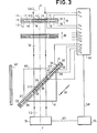
- the modulator of the invention therefore becomes as shown in FIG. 3.
- a light beam 50 received by the cell 10 along the axis XY is partly absorbed by the fluid lf2 due to its rate of absorption of light.
- the cell 10 therefore transmits an attenuated light beam.
- the cell 20 transmits a beam 51 without attenuation. It is the same for cell 30 as described above.
- the beam 52 emerging from the optical modulator has therefore been attenuated.
- control circuit 55 can, depending on the value of the signal supplied by the measuring device, control the generator 56 so that it applies a control voltage to the outputs V21 and V22 to the central electrodes of cell 20.
- the fluid in this cell moves and takes the same position as the fluid in cell 10.
- the light beam 50 after being attenuated by cell 10 is again attenuated by cell 20 and is transmitted by cell 30. An attenuation is obtained which is greater than the previous attenuation.
- the control circuit provides a signal on the link 58 such that the generator 56 applies a voltage between the outputs V33 and V34 greater than the voltage between the outputs V31 and V32.
- the electric field between the electrodes 37 and 38 of the cell 30 attracts the fluid 2f2 in the reservoirs 34 located on either side of the capillary space. Cell 30 goes into the state shown in figure 4.
- a beam 51 then reaches the blade 31 of the cell 30 and in the absence of the fluid 2f2, it is almost entirely reflected by the internal face of the blade, in the form of a beam 53, towards the absorbent panel 42. However, a small part of the incident beam 51 is transmitted and a low intensity beam 52 emerges from the modulator.
- FIGS. 2 to 4 only two cells 10 and 20 of the type showing an absorbent fluid have been shown.
- the useful space for the modulation of the light beam is the capillary space.
- the size of the tanks on either side of the cells can be a drawback and it is advantageous to reduce this size. Thicknesses of reservoirs greater than the thickness of the capillary spaces are then provided.
- the electrodes 17 and 18 framing the reservoirs follow the curvature of the blades 11 and 12 to facilitate the initiation of the movement of the fluid lf2.
- the cell transmits a beam without absorption; when the fluid is in the capillary space 13, the cell is absorbent.
- the blades 31 and 32 are folded at an angle ⁇ , for example 4 radians. They define a capillary space 33 inclined with respect to the XY axis and a reservoir 34 prependicular to the XY axis.
- the light beam 51 is still not deflected by the reservoir 34 which then contains air. This light beam reaches the capillary space 33 which, containing the fluid 2f2, transmits the light beam as in the case described in relation to FIG. 2.
- the thicknesses of the capillary space 33 and of the reservoir 34 have been chosen such that on the direction XY, the distance el between the two blades 31 and 32 is equal to the thickness e2. Whether the fluid is in the capillary space 33 or in the reservoir 34, a light beam during its transmission by the cell 30 will pass through the same thickness of fluid 2f2 and of air. The optical paths will therefore not be modified in transmission.
- the dimensions of the reservoir 33 are calculated, taking into account the thickness e2 to contain all of the fluid 2f2.
- the cell 10 is unchanged.
- the cell 30, produced analogously to the cell in FIG. 5 has its reservoir 33 arranged parallel to the axis XY. A light beam; crossing the cell will therefore not cross the tank 33.
- the glass slides of the cells are made of glass with a refractive index 1.5 and a thickness of 1.5 mm.
- the spacers (19-39) are cut from a polymer film, for example a film of "MYLAR” or “KAPTON", trademarks) registered with the firm DU PONT DE NEMOURS.
- the thickness of the spacers must be less than 1 mm for the capillary phenomena of fluids to take precedence over gravitational forces.
- spacers from 5 / ⁇ m to 50 / ⁇ m, and for reservoirs, spacers from 10 to 200 ⁇ m. Bonding the boards through the spacers seals the cell.
- the glass slides are equipped with their electrodes deposited and engraved according to microlithography techniques.
- the electrodes consist of deposits of indium tin oxide, for example of the BALTRACON type, sold by the company BALZERS. Annealing at 350 ° C makes them transparent to light.
- the representation of the electrodes in the appended figures has been simplified but it is specified that the interval separating two electrodes of the same plate, the electrodes 16 and 17 for example, must be of small width, of the order of 20 ⁇ m.
- two electrodes of the same blade can have jagged contours interpenetrating. This allows easier movement of the liquid between the electrodes.
- deposits such as RI and R2 in FIG. 1, are carried out. These very thin deposits have a thickness of the order of 10 nanometers.
- an organo silane deposit in particular of alkylmethoxysilane, and in particular N, N-dimethyl-N-octadecycle-3-aminopropyltrimethoxysilyl chloride. This deposit is polymerized under nitrogen at 110 ° after hydrolysis of the methoxysilane groups and formation by chemisorbtion on the substrate of hydrogen and siloxane bonds. Due to the thinness of these surface treatments, greater wettability is observed where the organic deposit covers electrodes.
- Fluorinated polymers can also constitute non-wetting confinement surfaces.
- the fluids lf2 and 2f2 they will be chosen so that their dielectric permittivity is different from that of the fluid f which can simply be air as mentioned previously.
- the liquid it is advantageous for the liquid to be displaced to be not very corrosive and not very conductive of electricity.
- the following fillers have been used successfully:
- dyes are mixed making it absorbent in a wavelength spectrum corresponding to the field of use of the modulator. It is thus possible to cover spectral absorption bands between for example 0.4 / ⁇ m and 1.1 ⁇ m.
- non-ionic dyes with high solubility are preferably used.
- Indophenol Blue, Sudan Blue and Sudan Black B have been successfully used in viisble.
- Anthraquinone dyes can also be used, which are particularly stable.
- mixtures of several dyes are used on cell overlays, of the type 10 and 20 described above, each containing one or more dyes.
- the volume of fluid lf2 or 2f2 introduced into a cell is such that it covers the electrodes of the capillary space, or even protrudes slightly to overlap the indentation of the contour of the electrodes, mentioned previously.
- the fluid placed in the capillary space is then in contact with the electrodes of the reservoirs and can be attracted more easily. Conversely, the arrangement is the same when the fluid is in the tanks.
- the prisms 40 and 41 are bonded to the blades 31 and 32 so that there is adaptation of index between blades and prisms.
- certain elements can be molded, for example in acrylic resins such as Polymethyl metalcrylate (PMMA, "plexiglass").
- the electrical connections to the generator 56 are made in providing an extension, not shown, to the transparent blades and by depositing therein, at the same time as the electrodes, connection pads on which a connector is then plugged in, or on which microwelds are produced.
- the attenuation of a cell such as cell 1 is, depending on the concentration of the dye introduced into the fluid 1f2, of the order of 10%. We can have at least five cells of this type without providing harmful attenuation when all the cells are busy, ie non-absorbent.
- the attenuation of cell 30 is of the order of 90%.
- the width L, mentioned in FIG. 5, of such a modulator is 5 to 10 mm.
- cells 10 containing an absorbent liquid there are cells 10 containing an absorbent liquid.
- these cells only have a single reservoir 14 located on the right of the capillary space 13.
- the operation of such a cell is identical to that of the cells described above.
- the width L of a cell 10 being also 10 mm, there are, aligned with the cells 30, the same number of cells, ie 7 to 8 cells.
- the length P of cells 10 is also 70 to 80 mm.
- Cells 10 and 30 can be associated in pairs as shown in Figure 8.
- Two cells 10 are grouped into one with, one its reservoir on the left, the other its reservoir on the right. They are produced with a single blade 11 and a single blade 12. A spacer 19 is provided in the central part.
- each of these cells are placed two cells 30 whose capillary spaces form a dihedral angle of 2 radians.
- the prisms 40 of these two cells are produced in a single prism 43.
- the prisms 41 of two adjacent cells are produced in a single prism 44.
- control circuits 55 not only independently control the various planes of modulator networks but also, selectively control each cell in each plane.
- cells of length equal to the width L As shown in FIG. 9, a square matrix of cells 10 is placed in a plane P10. For example, an 8 ⁇ 8 cell matrix is produced. Likewise, cells 20 are assembled in the form of a P20 plane and cells 30 in the form of a P30 plane. The planes P10, P20 and P30 are superimposed so that the cells with the same coordinates in the different planes are aligned along the same axis parallel to the XY axis.
Landscapes
- Physics & Mathematics (AREA)
- General Physics & Mathematics (AREA)
- Optics & Photonics (AREA)
- Mechanical Light Control Or Optical Switches (AREA)
- Investigating Or Analysing Materials By Optical Means (AREA)
- Optical Elements Other Than Lenses (AREA)
- Electrochromic Elements, Electrophoresis, Or Variable Reflection Or Absorption Elements (AREA)
- Light Guides In General And Applications Therefor (AREA)
Applications Claiming Priority (2)
| Application Number | Priority Date | Filing Date | Title |
|---|---|---|---|
| FR8316794A FR2553907B1 (fr) | 1983-10-21 | 1983-10-21 | Modulateur optique |
| FR8316794 | 1983-10-21 |
Publications (3)
| Publication Number | Publication Date |
|---|---|
| EP0141714A2 true EP0141714A2 (de) | 1985-05-15 |
| EP0141714A3 EP0141714A3 (en) | 1985-06-19 |
| EP0141714B1 EP0141714B1 (de) | 1987-05-20 |
Family
ID=9293389
Family Applications (1)
| Application Number | Title | Priority Date | Filing Date |
|---|---|---|---|
| EP84402077A Expired EP0141714B1 (de) | 1983-10-21 | 1984-10-16 | Optischer Modulator |
Country Status (5)
| Country | Link |
|---|---|
| US (1) | US4701021A (de) |
| EP (1) | EP0141714B1 (de) |
| JP (1) | JPS60114828A (de) |
| DE (1) | DE3463853D1 (de) |
| FR (1) | FR2553907B1 (de) |
Cited By (1)
| Publication number | Priority date | Publication date | Assignee | Title |
|---|---|---|---|---|
| EP1946183A4 (de) * | 2005-10-21 | 2009-08-19 | Nokia Corp | Optische blende für miniaturkameras |
Families Citing this family (31)
| Publication number | Priority date | Publication date | Assignee | Title |
|---|---|---|---|---|
| FR2621728B1 (fr) * | 1987-10-09 | 1990-01-05 | Thomson Csf | Systeme de visualisation d'images en demi-teintes sur un ecran matriciel |
| US5153870A (en) * | 1989-06-29 | 1992-10-06 | Digital Equipment Corporation | Rotary head actuator for optical disk |
| US5181016A (en) * | 1991-01-15 | 1993-01-19 | The United States Of America As Represented By The United States Department Of Energy | Micro-valve pump light valve display |
| FR2682798B1 (fr) * | 1991-10-22 | 1994-01-21 | Sextant Avionique | Procede et dispositif d'optimisation des performances d'un ecran matriciel a cristaux liquides en fonction de l'angle d'observation. |
| FR2683918B1 (fr) * | 1991-11-19 | 1994-09-09 | Thomson Csf | Materiau constitutif d'une lunette de visee et arme utilisant cette lunette. |
| CH687909A5 (de) * | 1991-12-31 | 1997-03-27 | Xelux Holding Ag | Verfahren zum Betrieb einer Blendschutzvorrichtung. |
| FR2696258B1 (fr) * | 1992-09-25 | 1994-10-28 | Sextant Avionique | Dispositif de gestion d'un système d'interaction homme-machine. |
| CH687809A5 (de) * | 1993-05-14 | 1997-02-28 | Xelux Holding Ag | Blendschutzvorrichtung. |
| DE4343808A1 (de) * | 1993-12-22 | 1995-06-29 | Thomson Brandt Gmbh | Lichtventil für Video-, Graphik und Datendisplay ohne Polarisationsfilter |
| JP3663212B2 (ja) * | 1994-10-25 | 2005-06-22 | コーニンクレッカ フィリップス エレクトロニクス エヌ ヴィ | フィルターを有するx線装置 |
| EP0786138B1 (de) * | 1995-07-13 | 1999-12-01 | Koninklijke Philips Electronics N.V. | Einen filter enthältende röntgenuntersuchungsvorrichtung |
| JPH10506039A (ja) * | 1995-07-13 | 1998-06-16 | フィリップス エレクトロニクス エヌ ベー | フィルタを含むx線検査装置 |
| US6085016A (en) * | 1998-06-15 | 2000-07-04 | Lucent Technologies, Inc. | Magnetically controlled variable optical attenuator |
| US6565727B1 (en) | 1999-01-25 | 2003-05-20 | Nanolytics, Inc. | Actuators for microfluidics without moving parts |
| AU2003263436A1 (en) * | 2002-09-19 | 2004-04-08 | Koninklijke Philips Electronics N.V. | Electrowetting optical switch |
| US7329545B2 (en) | 2002-09-24 | 2008-02-12 | Duke University | Methods for sampling a liquid flow |
| US6911132B2 (en) | 2002-09-24 | 2005-06-28 | Duke University | Apparatus for manipulating droplets by electrowetting-based techniques |
| EP1576345B1 (de) * | 2002-12-19 | 2008-12-17 | Koninklijke Philips Electronics N.V. | Optisches analysesystem |
| FI116245B (fi) * | 2003-06-17 | 2005-10-14 | Nokia Corp | Säädettävä optinen systeemi sekä menetelmä sen käyttämiseksi ja valmistamiseksi |
| GB0407231D0 (en) * | 2004-03-30 | 2004-05-05 | Koninkl Philips Electronics Nv | Variable lens |
| GB0407233D0 (en) * | 2004-03-30 | 2004-05-05 | Koninkl Philips Electronics Nv | Compact switchable optical unit |
| JP4833963B2 (ja) * | 2004-03-30 | 2011-12-07 | コーニンクレッカ フィリップス エレクトロニクス エヌ ヴィ | コンパクトな切替可能な光ユニット |
| DK1859330T3 (da) | 2005-01-28 | 2012-10-15 | Univ Duke | Apparater og fremgangsmåder til håndtering af små dråber på et trykt kredsløbskort |
| US7410309B2 (en) * | 2005-04-06 | 2008-08-12 | Nokia Corporation | Optical shutter |
| JP4872364B2 (ja) * | 2006-02-01 | 2012-02-08 | ソニー株式会社 | 液体移動装置 |
| KR101018737B1 (ko) | 2006-02-27 | 2011-03-04 | 노키아 코포레이션 | 조정가능한 효율을 가지는 회절 격자 |
| JP4442580B2 (ja) | 2006-03-28 | 2010-03-31 | ソニー株式会社 | 光学素子および撮像装置 |
| JP5224232B2 (ja) | 2006-09-27 | 2013-07-03 | Nltテクノロジー株式会社 | 表示装置 |
| US8268246B2 (en) * | 2007-08-09 | 2012-09-18 | Advanced Liquid Logic Inc | PCB droplet actuator fabrication |
| DE102009021638B4 (de) * | 2009-05-16 | 2020-02-20 | Leopold Kostal Gmbh & Co. Kg | Optischer Sensor |
| DE112009005301A5 (de) * | 2009-10-06 | 2013-01-03 | Seereal Technologies Gmbh | Optisches bauteil zur beeinflussung eines lichtstrahls |
Family Cites Families (3)
| Publication number | Priority date | Publication date | Assignee | Title |
|---|---|---|---|---|
| US3904868A (en) * | 1974-10-21 | 1975-09-09 | Us Navy | Continuously variable, reversible optical filter |
| GB1494150A (en) * | 1975-12-09 | 1977-12-07 | Standard Telephones Cables Ltd | Optical switch arrangement |
| JPS566203A (en) * | 1979-06-28 | 1981-01-22 | Nippon Telegr & Teleph Corp <Ntt> | Photoswitch |
-
1983
- 1983-10-21 FR FR8316794A patent/FR2553907B1/fr not_active Expired
-
1984
- 1984-10-16 DE DE8484402077T patent/DE3463853D1/de not_active Expired
- 1984-10-16 EP EP84402077A patent/EP0141714B1/de not_active Expired
- 1984-10-18 US US06/662,156 patent/US4701021A/en not_active Expired - Fee Related
- 1984-10-22 JP JP59220629A patent/JPS60114828A/ja active Pending
Cited By (1)
| Publication number | Priority date | Publication date | Assignee | Title |
|---|---|---|---|---|
| EP1946183A4 (de) * | 2005-10-21 | 2009-08-19 | Nokia Corp | Optische blende für miniaturkameras |
Also Published As
| Publication number | Publication date |
|---|---|
| EP0141714B1 (de) | 1987-05-20 |
| EP0141714A3 (en) | 1985-06-19 |
| JPS60114828A (ja) | 1985-06-21 |
| FR2553907B1 (fr) | 1985-12-13 |
| FR2553907A1 (fr) | 1985-04-26 |
| US4701021A (en) | 1987-10-20 |
| DE3463853D1 (en) | 1987-06-25 |
Similar Documents
| Publication | Publication Date | Title |
|---|---|---|
| EP0141714B1 (de) | Optischer Modulator | |
| EP0017571B1 (de) | Lichtintensitätsmodulator in integrierter Optik und integrierte optische Schaltung mit einem solchen Modulator | |
| EP0136193A1 (de) | Optische Schaltvorrichtung mittels Flüssigkeitsverschiebung und Zusammensetzungsvorrichtung einer Punktlinie | |
| EP0020216B1 (de) | Numerisch gesteuerter optischer Intensitätsmodulator in integrierter optischer Form und Digital-Analog-Umsetzer mit einem solchen Modulator | |
| FR2553906A1 (fr) | Dispositif de commutation optique a commande electrique | |
| EP0083520A1 (de) | Lichtstrahlen-Schaltgerät insbesondere für Telefonzentrale | |
| EP1447707A1 (de) | Vorrichtung zur räumlichen Modulation eines Lichtstrahls und entsprechende Anwendungen | |
| JP2010079297A (ja) | 光変調装置 | |
| FR2780520A1 (fr) | Modulateur d'intensite optique et son procede de fabrication | |
| WO2002103443A1 (fr) | Dispositif electrooptique, formant notamment commutateur, a base de cristaux liquides | |
| Hrudey et al. | Variable diffraction gratings using nanoporous electrodes and electrophoresis of dye ions | |
| EP0783127B1 (de) | Mach-Zehnder interferometricher Koppler mit optischer monomodiger Faser | |
| EP1356344A1 (de) | Einrichtung zur steuerung der polarisation in einer optischen verbindung | |
| FR2864636A1 (fr) | Dispositif d'egalisation optique et systeme correspondant | |
| FR2820827A1 (fr) | Dispositif d'attenuation d'un signal vehicule par fibre optique sous la forme d'un faisceau lumineux, systeme d'attenuation et applications correspondantes | |
| EP1444796A1 (de) | Dynamischer spektraler entzerrer mit einem programmierbaren holographischen spiegel | |
| EP4038447B1 (de) | Thermooptisch adressierter räumlicher lichtmodulator | |
| JP3433119B2 (ja) | 電気光学材料、それを用いた光素子および位相空間光変調器 | |
| EP0486357A1 (de) | Lichtstrahlablenker mit einem Bragg-Gitter | |
| EP0209439A1 (de) | Elektro-optische Anzeigevorrichtung mit Flüssigkristallen | |
| FR2608784A1 (fr) | Dispositif de commutation optique a plusieurs entrees et plusieurs sorties | |
| FR3166219A1 (fr) | Dispositif d’affichage d’une image | |
| FR2858857A1 (fr) | Filtre commandable a commutation rapide | |
| FR2764398A1 (fr) | Deflecteur electro-optique de faisceau lumineux, notamment pour adressage optique multipoints | |
| WO2003007056A1 (fr) | Filtre commandable a commutation rapide |
Legal Events
| Date | Code | Title | Description |
|---|---|---|---|
| PUAI | Public reference made under article 153(3) epc to a published international application that has entered the european phase |
Free format text: ORIGINAL CODE: 0009012 |
|
| PUAL | Search report despatched |
Free format text: ORIGINAL CODE: 0009013 |
|
| AK | Designated contracting states |
Designated state(s): DE GB NL SE |
|
| AK | Designated contracting states |
Designated state(s): DE GB NL SE |
|
| 17P | Request for examination filed |
Effective date: 19851002 |
|
| 17Q | First examination report despatched |
Effective date: 19860718 |
|
| GRAA | (expected) grant |
Free format text: ORIGINAL CODE: 0009210 |
|
| AK | Designated contracting states |
Kind code of ref document: B1 Designated state(s): DE GB NL SE |
|
| REF | Corresponds to: |
Ref document number: 3463853 Country of ref document: DE Date of ref document: 19870625 |
|
| PLBE | No opposition filed within time limit |
Free format text: ORIGINAL CODE: 0009261 |
|
| STAA | Information on the status of an ep patent application or granted ep patent |
Free format text: STATUS: NO OPPOSITION FILED WITHIN TIME LIMIT |
|
| 26N | No opposition filed | ||
| PGFP | Annual fee paid to national office [announced via postgrant information from national office to epo] |
Ref country code: DE Payment date: 19890923 Year of fee payment: 6 |
|
| PGFP | Annual fee paid to national office [announced via postgrant information from national office to epo] |
Ref country code: GB Payment date: 19890930 Year of fee payment: 6 |
|
| PGFP | Annual fee paid to national office [announced via postgrant information from national office to epo] |
Ref country code: SE Payment date: 19891024 Year of fee payment: 6 |
|
| PGFP | Annual fee paid to national office [announced via postgrant information from national office to epo] |
Ref country code: NL Payment date: 19891031 Year of fee payment: 6 |
|
| PG25 | Lapsed in a contracting state [announced via postgrant information from national office to epo] |
Ref country code: GB Effective date: 19901016 |
|
| PG25 | Lapsed in a contracting state [announced via postgrant information from national office to epo] |
Ref country code: SE Effective date: 19901017 |
|
| PG25 | Lapsed in a contracting state [announced via postgrant information from national office to epo] |
Ref country code: NL Effective date: 19910501 |
|
| GBPC | Gb: european patent ceased through non-payment of renewal fee | ||
| NLV4 | Nl: lapsed or anulled due to non-payment of the annual fee | ||
| PG25 | Lapsed in a contracting state [announced via postgrant information from national office to epo] |
Ref country code: DE Effective date: 19910702 |
|
| EUG | Se: european patent has lapsed |
Ref document number: 84402077.6 Effective date: 19910603 |