EP0141736A2 - Vorrichtung zur universellen Sichtkorrektur - Google Patents
Vorrichtung zur universellen Sichtkorrektur Download PDFInfo
- Publication number
- EP0141736A2 EP0141736A2 EP84402162A EP84402162A EP0141736A2 EP 0141736 A2 EP0141736 A2 EP 0141736A2 EP 84402162 A EP84402162 A EP 84402162A EP 84402162 A EP84402162 A EP 84402162A EP 0141736 A2 EP0141736 A2 EP 0141736A2
- Authority
- EP
- European Patent Office
- Prior art keywords
- transparent
- opaque
- zone
- vision
- corrector according
- Prior art date
- Legal status (The legal status is an assumption and is not a legal conclusion. Google has not performed a legal analysis and makes no representation as to the accuracy of the status listed.)
- Ceased
Links
Images
Classifications
-
- G—PHYSICS
- G02—OPTICS
- G02C—SPECTACLES; SUNGLASSES OR GOGGLES INSOFAR AS THEY HAVE THE SAME FEATURES AS SPECTACLES; CONTACT LENSES
- G02C7/00—Optical parts
- G02C7/16—Shades; shields; Obturators, e.g. with pinhole, with slot
- G02C7/165—Shades; shields; Obturators, e.g. with pinhole, with slot with stenopaeic apertures
Definitions
- the present invention relates to a universal vision corrector applying in particular to myopia, hyperopia, astigmatism and presbyopia.
- glasses are also known, the "glasses" of which in fact consist of opaque plates pierced with holes. Such a pair of glasses is described for example in US Pat. No. 3,967,885.
- a pair of glasses of this type has the drawback that the overall opacity of the surface of the glasses results in lateral occlusion of vision and a permanent dilation of the pupil which in turn causes tetanization of the muscle which controls the dilation and contraction of the pupil.
- the present invention relates to a vision corrector with a particularly simple design.
- this universal vision corrector comprising, in front of the eye, an opaque zone surrounding a small central zone situated in the axis of vision, this small transparent central zone forming a diaphragm and creating a reduced retinal image giving a visior clear, is characterized in that the opaque zone is continuous, it has a minimum average diameter of 3 mm and maximum d. 8 mm to maintain the peripheral vision, and the central transparent zone has a surface ranging from 0.2 to 3.5 mm 2 and preferably from 0.5% to 1 mm 2,
- opaque zone any surface preventing light rays from being perceived by the eye, while the “transparent zone”, consisting of a hole or a solid portion, lets the light rays pass, on the contrary.
- the opaque zone surrounding the central transparent zone can be produced independently, in an opaque material, by forming a sort of "washer” or else it can be formed on the front or rear face of a support in transparent material. .
- the transparent central zone can be formed, in this case, by the material of the support or by a hole drilled in it.
- a single vision corrector according to the invention can be used to correct the classic visual states, namely myopia, hyperopia, astigmatism and presbyopia because the reduced retinal image gives a clear vision while retaining the peripheral field, which is essential in social life and in practical terms.
- the transparent central zone preferably has a surface of 0.5 to 1 mm 2 and the opaque zone also preferably has a diameter of 4 to 5 mm.
- the vertical and horizontal fields of vision are respectively 1200 and 15n o ; although the field of vision is only 1 minute angle, you can increase the field of vision by combining, on the same transparent support, several "washers", that is to say several transparent central zones respectively surrounded by opaque areas. The distance between the transparent zones depends on the diameters of these to avoid interference. This arrangement allows to find the normal field of vision without requiring a rotation of the tate.
- the transparent central zones can have any suitable geometric shape, for example circular, rectangular or even elliptical, the opaque zone surrounding it having a homothetic surface or not.
- the corrector according to the invention can be used for very different applications. It can in particular be used in the form of a pair of glasses.
- the interpupillary distance must be respected, which is, for men, from 63 to 68 mm and, for women, from 60 mm to 64 mm.
- each transparent support is mounted adjustable in position on a common transverse and horizontal bar and once the adjustment corresponding to the interpupillary distance obtained, it is immobilized in position, by any appropriate means.
- the frame is produced in two fixed parts, connected to each other by an intermediate bar, of suitable length to adapt to the interpupillary distances of the various people.
- the frame and the lenses are fixed and the location of the transparent point areas on each of the two lenses is chosen as a function of the interpupillary distance from the wearer of the glasses.
- the corrector according to the invention can also be used with sighting devices such as cameras, cameras, binoculars, microscopes etc., to allow better vision for people with a need.
- the transparent support having the transparent central zone bordered by the opaque zone, can be fixed directly on the eyepiece, for example by gluing, or preferably at 1 cm from it, to increase the field of vision.
- One can also directly form the opaque area on the eyepiece itself, by etching or any other means.
- transparent support can also be adapted to glasses for television, the transparent support then being slightly colored, or even to glasses for vision in relief (transparent support red on one side and blue on the other).
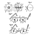
- the universal ametropia corrector which is represented in FIG. 1, comprises an opaque zone 2 surrounding a central zone 3 transparent, of small dimension and forming "diaphranme".
- This transparent central zone 3 can have any suitable shape, in particular circular, polygonal, elliptical or other, as well as the opaque zone? the entran has sucface the area opaque 2 is homothetic to that of the surface of the central transparent zone 3 or different from this homothetic surface.
- the surface of the transparent central zone 3 forming a diaphragm must be between 0.2 and 3.5 mm 2.
- a surface of 0.5 mm2 makes it possible to obtain a good correction for common ametropias ranging from 0.25 to 10 diopters, the opaque zone 2 which surrounds it having a minimum surface of 27 mm 2 . If we respect these conditions, we get a clear vision, whatever the visual state to compensate and without aberrations.
- the corrector according to the invention makes it possible, due to the presence of the continuous opaque zone of small dimensions, to obtain clear images while preserving the peripheral visual field.
- the opaque zone 2 can be completely independent and it can constitute a sort of "washer” made of an opaque material, the transparent central zone 3 being formed by a single hole.
- the opaque zone 2 can also be deposited or glued to a support 4 made of transparent material as shown in FIG. 1, the transparent central zone 3 then being constituted by the support portion 4 being located in the center of the opaque zone 2.
- the transparent support 4 can have the form of a usual spectacle lens, as shown in FIGS. 2 and 3.
- FIG. 2 illustrates a pair of glasses comprising a common transverse and horizontal bar 5 under which are fixed the two transparent supports 4 associated respectively with the two eyes.
- Each of these supports can be moved on the bar 5, for example by 2 mm. to allow adaptation of the distance between the two supports 4 to the interpupillary distance of the spectacle wearer. Once the appropriate distance is obtained, we set definitely each support 4 on the bar 5, by any appropriate means, for example by a clip or a quick bonding.
- the frame of the pair of glasses is made up of two parts each comprising a transparent support 4 on which is hinged, around a hinge 6, a branch 7 of the frame.
- the two supports 4 are also connected horizontally by an intermediate bar 8 of variable length suitable for the interpupillary distance of the wearer.
- This intermediate bar 8 can be made in telescopic form.
- the corrector according to the invention can also form part of an eyeglass resting on the nose, the two “washers” then being connected, by a single wire, to the part of the eyeglass bearing on the nose.
- FIG. 4 illustrates the use of the corrector according to the invention as a contact lens.
- This contact lens comprises, as in the previous cases, a transparent support 9 having the shape of a curved surface whose radius of curvature corresponds to the cornea treated.
- This transparent support 9 also has an opaque zone 11 surrounding a transparent central zone 12 of small size.
- FIG. 5 illustrates the case of several opaque zones 2 provided on the same transparent support 4 and aligned along a horizontal plane H and each surrounding a transparent central zone 3 of small dimension. Three neighboring opaque zones 2 are sufficient to ensure good vision in the horizontal field. A similar arrangement can also be adopted in the vertical plane.
- the corrector may consist of a piece of an opaque perforated strip, at regular intervals, of holes arranged in staggered rows, the distance between the elementary holes forming diaphragms being greater than or equal to 3 mm.
- this corrector in the case of use of the corrector in the form of a pair of glasses, this corrector can be constituted by an opaque washer, transparent in its central part, which is deposited, by screen printing or by any other means, on each of the two lenses of a pair of conventional spectacles, and this in locations corresponding to the interpupillary distance from the wearer of the spectacles.
- Other auxiliary washers are arranged around this main washer corresponding to the interpupillary distance. This allows the use of a single standard frame, fitted with its transparent lenses, for all users, regardless of the interpupillary distance of these.
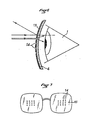
- the corrector which is shown in FIGS. 6 and 7, in front of the eye 1, comprises a transparent support 4, for example made of glass or plastic, on the front face of which a thin layer 13 reflecting light is deposited.
- This layer 13 does not reflect the entire incident light beam, but it lets a more or less weak part of this incident light flux pass, so that the eye can see through the relatively opaque thin layer 13, but with a weakening of the brightness.
- this thin reflective and slightly transparent layer 13 are left transparent point zones 14 of small dimension and forming "diaphragms". These transparent point zones 14 can also be formed by holes drilled right through in the transparent support 4 and the layer thin reflective 13.
- each transparent point zone 14 forming the strip must be between 0.2 and 3.5 mm 2 and it is preferably around 1 mm 2 .
- the transparent support 4 can have the usual shape of a glass - of a pair of glasses as shown in FIG. 7.
- each glass has a reflective front surface 13 in the central part of which a group is formed transparent point zones 14 distant from each other.
- These zones 14 are advantageously distributed at a minimum distance of approximately 3mm from each other. They can be distributed in a matrix arrangement, that is to say in rows and columns, as shown in FIG. 7.
- the corrector can constitute a contact lens, also called “contact lens or lens”, on which a central transparent zone surrounded by a border is left, by screen printing or any other means. opaque to light.
- contact lens also called "contact lens or lens”
- the manufacture of these lenses is considerably simplified compared to contact lenses currently known: in fact a single model is suitable for all people with any visual need.
- two or three different radii of curvature can be provided depending on the diameters of the corneas to be treated.
- These lenses must have low mobility in front of the pupil. If they are made of a suitable material, disposable lenses are obtained, maintenance-free or permanent wear.
- the corrector constitutes a contact lens or contact lens
- the known opaque zone preferably a reservoir of a liquid product which can be used for therapeutic or hygienic purposes.
Landscapes
- Health & Medical Sciences (AREA)
- Ophthalmology & Optometry (AREA)
- Physics & Mathematics (AREA)
- General Health & Medical Sciences (AREA)
- General Physics & Mathematics (AREA)
- Optics & Photonics (AREA)
- Eyeglasses (AREA)
- Rehabilitation Tools (AREA)
Applications Claiming Priority (6)
| Application Number | Priority Date | Filing Date | Title |
|---|---|---|---|
| FR8317244A FR2554249B1 (fr) | 1983-10-28 | 1983-10-28 | Correcteur universel d'ametropies de l'oeil |
| FR8400388 | 1984-01-12 | ||
| FR8400388A FR2558269B2 (fr) | 1984-01-12 | 1984-01-12 | Correcteur universel d'ametropies de l'oeil |
| FR8411447 | 1984-07-19 | ||
| FR8411447A FR2568022B1 (fr) | 1984-07-19 | 1984-07-19 | Correcteur universel d'ametropies de l'oeil |
| FR8317244 | 1984-07-19 |
Publications (2)
| Publication Number | Publication Date |
|---|---|
| EP0141736A2 true EP0141736A2 (de) | 1985-05-15 |
| EP0141736A3 EP0141736A3 (de) | 1985-06-19 |
Family
ID=27251180
Family Applications (1)
| Application Number | Title | Priority Date | Filing Date |
|---|---|---|---|
| EP84402162A Ceased EP0141736A3 (de) | 1983-10-28 | 1984-10-26 | Vorrichtung zur universellen Sichtkorrektur |
Country Status (6)
| Country | Link |
|---|---|
| US (1) | US4958922A (de) |
| EP (1) | EP0141736A3 (de) |
| AU (1) | AU3506884A (de) |
| CA (1) | CA1264579A (de) |
| MA (1) | MA20257A1 (de) |
| WO (1) | WO1985002028A1 (de) |
Cited By (8)
| Publication number | Priority date | Publication date | Assignee | Title |
|---|---|---|---|---|
| EP0189331A1 (de) * | 1985-01-24 | 1986-07-30 | Kabushiki Kaisha Shuho | Objektives Material |
| FR2618915A1 (fr) * | 1987-05-25 | 1989-02-03 | Maignant Albert | Verre correcteur pour soulager les troubles dus a la myopathie oculaire |
| FR2646524A1 (fr) * | 1989-04-28 | 1990-11-02 | Blanie Paul | Lunettes perfectionnees |
| FR2655431A1 (fr) * | 1989-12-04 | 1991-06-07 | Bernard Rene | Lunettes stenopeiques. |
| WO1996013750A1 (de) * | 1994-11-01 | 1996-05-09 | Laser Micro Präzision Lmp Gmbh | Sehlochblende und sehhilfe mit sehlochblende |
| WO2000005618A1 (en) * | 1998-07-23 | 2000-02-03 | Peter Joseph Duthie | Ophthalmic device |
| RU2160458C2 (ru) * | 1996-10-07 | 2000-12-10 | Бакусов Леонид Михайлович | Устройство для коррекции зрения |
| RU2176809C2 (ru) * | 1999-02-05 | 2001-12-10 | Мережников Михаил Иванович | Очки |
Families Citing this family (18)
| Publication number | Priority date | Publication date | Assignee | Title |
|---|---|---|---|---|
| GB8529595D0 (en) * | 1985-12-02 | 1986-01-08 | Iris Optics Ltd | Reading glasses |
| AU601026B2 (en) * | 1987-03-10 | 1990-08-30 | James Shreenan | Golfer position viewing device |
| EP1173790A2 (de) | 1999-03-01 | 2002-01-23 | Boston Innovative Optics, Inc. | Vorrichtung und verfahren zur erhöhung der tiefenschärfe des menschlichen auges |
| WO2001084219A1 (en) * | 2000-04-25 | 2001-11-08 | Voyant.Com | Device for alleviating computer vision syndrome |
| US7628810B2 (en) | 2003-05-28 | 2009-12-08 | Acufocus, Inc. | Mask configured to maintain nutrient transport without producing visible diffraction patterns |
| US20050046794A1 (en) | 2003-06-17 | 2005-03-03 | Silvestrini Thomas A. | Method and apparatus for aligning a mask with the visual axis of an eye |
| US7976577B2 (en) | 2005-04-14 | 2011-07-12 | Acufocus, Inc. | Corneal optic formed of degradation resistant polymer |
| US20070258041A1 (en) * | 2006-05-04 | 2007-11-08 | Augustus Huang | Astigmia correcting eyeglasses |
| US7857448B2 (en) * | 2006-05-04 | 2010-12-28 | Proview Optical Group Corp. | Astigmia correcting eyeglasses |
| US9492272B2 (en) | 2009-08-13 | 2016-11-15 | Acufocus, Inc. | Masked intraocular implants and lenses |
| USD656526S1 (en) | 2009-11-10 | 2012-03-27 | Acufocus, Inc. | Ocular mask |
| US9224024B2 (en) * | 2011-11-11 | 2015-12-29 | Honeywell International, Inc. | Invariant design image capture device |
| WO2013082545A1 (en) | 2011-12-02 | 2013-06-06 | Acufocus, Inc. | Ocular mask having selective spectral transmission |
| US9204962B2 (en) | 2013-03-13 | 2015-12-08 | Acufocus, Inc. | In situ adjustable optical mask |
| US9427922B2 (en) | 2013-03-14 | 2016-08-30 | Acufocus, Inc. | Process for manufacturing an intraocular lens with an embedded mask |
| TWI485465B (zh) * | 2013-05-16 | 2015-05-21 | Tzoo Ying Entpr Co Ltd | 保眼裝置 |
| CN105182563A (zh) * | 2015-08-27 | 2015-12-23 | 杨克忠 | 一种用于消除眼睛散光的遮裂隙镜片及其消除散光方法 |
| CN120993630A (zh) | 2020-03-01 | 2025-11-21 | 恩塔米克控股有限公司 | 光学膜 |
Family Cites Families (13)
| Publication number | Priority date | Publication date | Assignee | Title |
|---|---|---|---|---|
| DE621084C (de) * | 1935-11-01 | Max Jeanneret Dr | Schiessbrille | |
| US459563A (en) * | 1891-09-15 | Device for assisting vision | ||
| FR7201E (fr) * | 1906-11-23 | 1907-06-01 | Societe A. A. Tunmer & C° | Perfectionnements aux lunettes d'automobilistes |
| FR398850A (fr) * | 1908-04-03 | 1909-06-15 | Max Landesberg | Binocle ou lunettes sans verres pouvant servir pour myopes et presbytes |
| FR389850A (fr) * | 1908-05-02 | 1908-09-19 | Richard Zelle | Boite d'allumettes avec calendrier et coupe-cigares |
| FR1020646A (fr) * | 1950-06-21 | 1953-02-09 | Procédés et dispositifs pour éliminer l'éblouissement des phares d'automobiles et toutes autres sources de lumière | |
| US2856813A (en) * | 1955-05-03 | 1958-10-21 | Kudelko Antonia | Spectacle frame with adjustable bridge and temples |
| FR1330277A (fr) * | 1962-05-09 | 1963-06-21 | Lunettes protectrices et correctrices à diaphragme réglable pour spectateurs de télévision et cinéma | |
| CH447650A (fr) * | 1966-05-04 | 1967-11-30 | Courvoisier Jean Pierre | Dispositif destiné à rendre imperceptibles à l'oeil les lignes de trame apprentes, ainsi que la vibration d'une image mobile observée sur un écran |
| US3507566A (en) * | 1968-04-29 | 1970-04-21 | Arthur A Knapp | Contact lens and spectacle lens structure |
| FR2389912A1 (en) * | 1977-05-06 | 1978-12-01 | Carreau Bernard | Protective spectacle lens construction - reduces light transmitted to peripheral retinal regions using fibre optic patch with hole in centre |
| US4249803A (en) * | 1979-07-10 | 1981-02-10 | William H. Byler | Optical device for pre-operative cataract patients |
| FR2498769B2 (fr) * | 1979-07-12 | 1988-09-23 | Bernet Roger | Lunettes stenopeiques ameliorees |
-
1984
- 1984-10-26 EP EP84402162A patent/EP0141736A3/de not_active Ceased
- 1984-10-26 AU AU35068/84A patent/AU3506884A/en not_active Abandoned
- 1984-10-26 WO PCT/FR1984/000244 patent/WO1985002028A1/fr not_active Ceased
- 1984-10-26 MA MA20481A patent/MA20257A1/fr unknown
- 1984-10-29 CA CA000466530A patent/CA1264579A/fr not_active Expired - Lifetime
-
1989
- 1989-03-06 US US07/319,904 patent/US4958922A/en not_active Expired - Fee Related
Cited By (12)
| Publication number | Priority date | Publication date | Assignee | Title |
|---|---|---|---|---|
| EP0189331A1 (de) * | 1985-01-24 | 1986-07-30 | Kabushiki Kaisha Shuho | Objektives Material |
| US4750812A (en) * | 1985-01-24 | 1988-06-14 | Kabushika Kaisha Shuho | Objective observation optical material |
| FR2618915A1 (fr) * | 1987-05-25 | 1989-02-03 | Maignant Albert | Verre correcteur pour soulager les troubles dus a la myopathie oculaire |
| FR2646524A1 (fr) * | 1989-04-28 | 1990-11-02 | Blanie Paul | Lunettes perfectionnees |
| EP0480113A1 (de) * | 1989-04-28 | 1992-04-15 | Paul Blanié | Verbesserte Brille |
| FR2655431A1 (fr) * | 1989-12-04 | 1991-06-07 | Bernard Rene | Lunettes stenopeiques. |
| WO1991008506A1 (fr) * | 1989-12-04 | 1991-06-13 | Bernard Rene George | Lunettes stenopeiques |
| WO1996013750A1 (de) * | 1994-11-01 | 1996-05-09 | Laser Micro Präzision Lmp Gmbh | Sehlochblende und sehhilfe mit sehlochblende |
| RU2160458C2 (ru) * | 1996-10-07 | 2000-12-10 | Бакусов Леонид Михайлович | Устройство для коррекции зрения |
| WO2000005618A1 (en) * | 1998-07-23 | 2000-02-03 | Peter Joseph Duthie | Ophthalmic device |
| GB2345350A (en) * | 1998-07-23 | 2000-07-05 | Peter Joseph Duthie | Ophthalmic device |
| RU2176809C2 (ru) * | 1999-02-05 | 2001-12-10 | Мережников Михаил Иванович | Очки |
Also Published As
| Publication number | Publication date |
|---|---|
| AU3506884A (en) | 1985-05-22 |
| EP0141736A3 (de) | 1985-06-19 |
| US4958922A (en) | 1990-09-25 |
| WO1985002028A1 (fr) | 1985-05-09 |
| MA20257A1 (fr) | 1985-07-01 |
| CA1264579A (fr) | 1990-01-23 |
Similar Documents
| Publication | Publication Date | Title |
|---|---|---|
| CA1264579A (fr) | Correcteur universel de vision | |
| BE1013846A5 (fr) | Lentille a distance focale variable. | |
| EP3642667B1 (de) | Orthokeratologische kontaktlinse zur behandlung von myopie | |
| CA2708516C (fr) | Lentille ophtalmique progressive | |
| FR2584823A1 (fr) | Lentille multifocale progressive et lunettes employant cette lentille | |
| US7984987B1 (en) | Eyewear with pinhole aperture and lens | |
| FR2533708A1 (fr) | Lentille ophtalmique multifocale progressive | |
| FR2545615A1 (fr) | Lentille ophtalmique multifocale progressive | |
| FR2508186A1 (fr) | Lentille ophtalmique a pouvoir progressif | |
| FR2916864A1 (fr) | Verre ophtalmique progressif de correction de myopie et procede de realisation d'un tel verre | |
| EP2294473A1 (de) | Augenoptisches glas und brille mit mindestens einem solchen glas | |
| FR2908897A1 (fr) | Lentilles ophtalmiques colorees multi-teintes. | |
| FR2582416A1 (fr) | Lentille de contact bifocale | |
| EP1744202B1 (de) | Progressive Brillenlinse | |
| CA3076789C (fr) | Ensemble constitue d'une paire d'implants oculaires multifocaux | |
| FR2948467A1 (fr) | Masque de vision | |
| FR2622984A1 (fr) | Lentille de contact formant filtre solaire | |
| EP0051613B1 (de) | Provisorische optische korrektureinrichtung, die die auswahl eines geeigneten brillengestells ermöglicht | |
| CA2604406C (fr) | Lentille ophtalmique | |
| FR2554249A1 (fr) | Correcteur universel d'ametropies de l'oeil | |
| JPH063630A (ja) | 眼 鏡 | |
| EP0927905A1 (de) | Optisches Verfahren für Amblyopia | |
| FR2568022A1 (fr) | Correcteur universel d'ametropies de l'oeil | |
| WO1991008506A1 (fr) | Lunettes stenopeiques | |
| EP1114351B1 (de) | Verfahren zum schnellmontieren von sehhilfen |
Legal Events
| Date | Code | Title | Description |
|---|---|---|---|
| PUAI | Public reference made under article 153(3) epc to a published international application that has entered the european phase |
Free format text: ORIGINAL CODE: 0009012 |
|
| PUAL | Search report despatched |
Free format text: ORIGINAL CODE: 0009013 |
|
| AK | Designated contracting states |
Designated state(s): AT BE CH DE GB IT LI LU NL SE |
|
| AK | Designated contracting states |
Designated state(s): AT BE CH DE GB IT LI LU NL SE |
|
| RTI1 | Title (correction) | ||
| 17P | Request for examination filed |
Effective date: 19851115 |
|
| 17Q | First examination report despatched |
Effective date: 19870310 |
|
| STAA | Information on the status of an ep patent application or granted ep patent |
Free format text: STATUS: THE APPLICATION HAS BEEN REFUSED |
|
| 18R | Application refused |
Effective date: 19890707 |
|
| APAF | Appeal reference modified |
Free format text: ORIGINAL CODE: EPIDOSCREFNE |