EP0141785A2 - Vorrichtung zum Halten einer Tür, insbesondere Panzertür in einer Spaltstellung - Google Patents
Vorrichtung zum Halten einer Tür, insbesondere Panzertür in einer Spaltstellung Download PDFInfo
- Publication number
- EP0141785A2 EP0141785A2 EP84830286A EP84830286A EP0141785A2 EP 0141785 A2 EP0141785 A2 EP 0141785A2 EP 84830286 A EP84830286 A EP 84830286A EP 84830286 A EP84830286 A EP 84830286A EP 0141785 A2 EP0141785 A2 EP 0141785A2
- Authority
- EP
- European Patent Office
- Prior art keywords
- fact
- pin
- thin part
- projecting stop
- door
- Prior art date
- Legal status (The legal status is an assumption and is not a legal conclusion. Google has not performed a legal analysis and makes no representation as to the accuracy of the status listed.)
- Granted
Links
Images

Classifications
-
- E—FIXED CONSTRUCTIONS
- E05—LOCKS; KEYS; WINDOW OR DOOR FITTINGS; SAFES
- E05C—BOLTS OR FASTENING DEVICES FOR WINGS, SPECIALLY FOR DOORS OR WINDOWS
- E05C17/00—Devices for holding wings open; Devices for limiting opening of wings or for holding wings open by a movable member extending between frame and wing; Braking devices, stops or buffers, combined therewith
Definitions
- the invention relates to a device for blocking doors, particularly armour plated doors, in a partly open position.
- the housings made in the floor are, in particular, defined by a cylindrical hole in which, tightly in the hole, a hollow element is sunk.
- the corresponding rod of the door generally fits into the said hollow element with a certain play in order to avoid the rod having to be forced or the installation operations having to be too exact.
- Doors provided to give security normally answer the specific protection function in a satisfactory way but are efficacious only in the closed position.
- the said doors cannot, in fact, be blocked efficiently in a partly open position whereby one is able to make a visual check or to perform operations (for example receiving the post) for which the door does not have to be opened fully.
- the devices that allow a door to be put ajar for the purposes stated are contrivances of a conventional type with poor resistance, inadequate, therefore; to give proper security.
- the said known devices cause considerable prao- tical problems when it is wished to fit them to an armour.
- plated door the penetration of the metal facing necessitates the use of highly efficient drills and of connection elements which, though continuing to be relatively weak, cannot be found readily on the market.
- the installation difficulty is particularly acute when the fact is taken into consideration that the said devices are generally mounted by the users themselves.
- the general fundamental object of the invention is to solve the said technical problem.
- one important object of the invention is to devise a device of extremely simple structure and of low cost able, therefore, to be adopted on a general scale by people who own armour plated doors.
- Another important object of the invention is to devise a device that does not require any specific installation operation since it can be fitted immediately to a door.
- a further object still of the invention is to devise a device that has obvious universal use characteristics, that is to say, a device that can be adapted to various types of doors or armour plated doors, is possible to include at the time a door is being installed or to fit thereto at a later date, and the purpose of which is to prevent any possibility of the blocking of the door being overcome by force applied to the outside of the door.
- the device according to the invention for blocking doors, particularly armour plated doors, in a partly open position, characterized by the fact of consisting in an arm able to be oscillated, defined by at least one pin that,fits rotatably, in a way in which it is virtually invisible, in a housing fixed in the floor at the base of the said door, the said pin being placed at the side of the jamb of the said door; by a thin part inserted loosely between the base of the said door and the floor there under, that extends perpendicularly to and is integral with the said pin; and by a projecting stop that is integral with the said thin part and juts out from this spaced a distance away from the said pin such as to allow it to hit against the said door when this is partly open.
- the said projecting stop is connected to the said thin movable part through means that allow the former to be fixed along the latter in a plurality of positions.
- the device according to the invention is shown globally at 1.
- the said device can be fitted to any type of door, though preferably the use thereof is envisaged on armour plated doors, shown at 2 in Figure 1.
- the said doors differ from others because of being, amongst other things, provided with locks equipped with rods or bolts 3 that are inserted in housings in the floor, placed at the base of the said doors. Though the actual location of the said bolts 3 can vary, the positioning thereof is always at least at points corresponding to the jamb of the door 2.
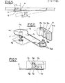
- the device 1 is constituted by an arm that is able to be oscillated and, in essence, comprises a pin 4, a thin blade part 5 that juts out perpendicular to and integral with the said pin 4, and a projecting stop 6 integral with the thin part 5, on the opposite side to the pin 4.
- the pin 4 is of the type that fits rotatably, in a way in which invisible, in a housing 1a of the said type that is placed in the floor at the base of the door 2.
- the overall volume of the pin 4 has to be less than the area of the said housing so that free rotation be possible.
- the pin 4 can be inserted directly therein without additional intermediate elements.
- the pin 4 can be solid or closed in at the top by the blade part 5.
- the pin 4 will, instead, be hollow ( Figures 2, 3 and 4), while the internal hole will be of sufficient a diameter to permit the bolt 3 to be inserted easily.
- the blade part 5 From the pin 4 extends the blade part 5 which has essentially to be thin so as to be able to be inserted between the base of the door 2 and the floor there under, without hindering the door.
- the blade part 5 has to be of a length, jutting out from the pin 4, directly proportional to the degree of opening required for the door to which the device is fitted.
- the projecting stop 6 is integral with the blade part 5 and is placed in the region of the furthermost extremity of the latter from the pin 4. Furthermore, the projecting stop 6 extends along the opposite side of the blade part 5 to that integral with the pin 4.
- the projecting stop 6 can assume a wide variety of shapes, as can, in the same way, the profile of the blade part 5. It can be seen, for example, in Figure 3 that the projecting stop 6 is defined by a folded back section of the blade part 5, while in Figure 4 the said projecting stop 6 is a block integral with the blade part 5 and provided with an abutment element 66.
- the device depicted in Figure 4 has the blade part 5 not directly connecting the pin 4 to the projecting stop 6 but extending in a direction at the side of the said stop. It is envisaged, in fact, that the device depicted in Figure 4 be fitted to double doors, with the blade part 5 placed beneath the part of the door that is kept closed, when in the non operative position.
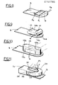
- the projecting stop 6. is defined by a fixed part constituted by locator surfaces 3a integral with the thin part 5 and made in one piece there with, and by a movable slot-in slide 3b.
- the said slide 3b is provided with abutment surfaces 4a destined to engage in a removable fashion with the locator surfaces 3a, and also has sliding surfaces 5a destined to permit the said slide 3b to move forward easily, following a thrust applied to a terminal surface 6a.
- the projecting stop 6 is defined, similarly to what has been described previously, by two parts that are removable one from the other, namely a central vertical tooth 7a integral with the thin part 5, and a grooved insert 7b.
- the latter is provided with a longitudinal slot 7c destined to couple with the tooth 7a that has in the centre, a housing 7d with a plurality of stop grooves 7e designed to couple with a pair of locking pins 7f.
- the projecting stop in Figure 8, again given overall the number 6, is defined by an extremity block 9a integral with the thin part 5 and such as to assume a wide variety of shapes, and by a frame 9b.
- the latter is connected to the thin part 5 by means of a pivot 9c that enables the said frame 9b to adopt two positions, namely a position above the thin part 5 and a position external thereto.
- the projecting stop 6 is constituted by a fixed part 10a integral with the thin part 5, and by a hinged block 10b.
- the latter is connected to the fixed part 10a through a supporting pivot 10c that enables the said block 10b to adopt two positions, namely a position above the thin part 5 and a position external thereto.
- the block 10b is provided with surfaces 11 that aid and render easy the overturning thereof under the control of a foot.
- Shown in Figure 10 is a projecting stop 6 constituted by a vertical pin 12a integral with the thin part 5, and by a shaped rotatable block 12b pivotally connected in an eccentric fashion to the vertical pin 12a.
- the said shaped block is able to be fashioned in a wide variety of forms and to be placed in a plurality of angular positions. It can be abutted with a stop 12c integral with the thin part 5.
- the said shaped block 12b,. is held in the working position by means of a spring 13 that is able to encourage the correct positioning thereof.
- FIG. 11 One particular solution of this type is illustrated diagrammatically in Figure 11 and this envisages, integral with the thin part 5, a front raised part 20 provided with a circular protrusion 21 in which there are two vertical housings 22. To the said protrusion 21 is coupled a movable element 23, the shape of which matches that of the said protrusion, and this is pivoted at 24 to the said raised part 20 via an arm 25 that is integral with the movable element 23 and can be distorted elastically when subjected to upward stress as shown with the arrow F.
- the element 23, thus acting as a raised stop, is provided with two projections 26 in positions complementary to the vertical housings 22, and it can adopt two distinct stable configurations illustrated in Figure 11 with an unbroken and a broken line, respectively, by simply raising and rotating the said element 23 by approximately 90°, the raising causing a disengagement between the projections 26 and the vertical housings 22.
- the projecting stop 6 is normally placed outside the area swept by the bottom of the door at the time the stop is in the non-operative position. Furthermore, in the said position the blade part 5 extends in a direction identical to the development direction of the door when in the closed position.
- the said non-operative position corresponds to a free space equal to L between the pin 4 and the projecting stop 6, greater than the length L 2 between the pin 4 and the edge of the door (see Figure 5).
- the new position of the projecting stop 6 is, in fact, such as to always remain within the area swept by the opening of the door, and thus no rotation given from the outside will be able to unblock the door.
- steps can be taken to couple the two through a thread (see Figure 6) by giving the pin 4 a vertical axis pivotal coupling 1b and providing a plurality of gaps 1e reached, for example, through an upper hole 1d for blocking, for example using an external tool, the pin 4 and the thin part 5 one to the other during the screwing in phase.
- the invention is liable to undergo numerous modifications and variants and, depending upon the requirements, the shapes and sizes of the parts, as also the materials used, can be of any type.
Landscapes
- Engineering & Computer Science (AREA)
- Mechanical Engineering (AREA)
- Closing And Opening Devices For Wings, And Checks For Wings (AREA)
Priority Applications (1)
| Application Number | Priority Date | Filing Date | Title |
|---|---|---|---|
| AT84830286T ATE35301T1 (de) | 1983-10-28 | 1984-10-23 | Vorrichtung zum halten einer tuer, insbesondere panzertuer in einer spaltstellung. |
Applications Claiming Priority (4)
| Application Number | Priority Date | Filing Date | Title |
|---|---|---|---|
| IT360083 | 1983-10-28 | ||
| IT8303600A IT1208102B (it) | 1983-10-28 | 1983-10-28 | Dispositivo per bloccare porte in posizione semiaperta, in particolare porte blindate |
| IT03440/84A IT1179320B (it) | 1984-04-20 | 1984-04-20 | Dispositivo a braccio oscillabile per bloccare porte in posizione semiaperta |
| IT344084 | 1984-04-20 |
Publications (3)
| Publication Number | Publication Date |
|---|---|
| EP0141785A2 true EP0141785A2 (de) | 1985-05-15 |
| EP0141785A3 EP0141785A3 (en) | 1986-06-04 |
| EP0141785B1 EP0141785B1 (de) | 1988-06-22 |
Family
ID=26325389
Family Applications (1)
| Application Number | Title | Priority Date | Filing Date |
|---|---|---|---|
| EP19840830286 Expired EP0141785B1 (de) | 1983-10-28 | 1984-10-23 | Vorrichtung zum Halten einer Tür, insbesondere Panzertür in einer Spaltstellung |
Country Status (2)
| Country | Link |
|---|---|
| EP (1) | EP0141785B1 (de) |
| DE (1) | DE3472282D1 (de) |
Cited By (2)
| Publication number | Priority date | Publication date | Assignee | Title |
|---|---|---|---|---|
| WO1999024686A1 (en) * | 1997-11-10 | 1999-05-20 | Wells, Michael | Door locking device |
| WO2007012873A1 (en) * | 2005-07-29 | 2007-02-01 | Force Entry Locking Systems Limited | Security device |
Family Cites Families (1)
| Publication number | Priority date | Publication date | Assignee | Title |
|---|---|---|---|---|
| DE40326C (de) * | H. HÄRTUNG in Berlin, Prenzlauerstr. 41 | Thürversperrer |
-
1984
- 1984-10-23 DE DE8484830286T patent/DE3472282D1/de not_active Expired
- 1984-10-23 EP EP19840830286 patent/EP0141785B1/de not_active Expired
Cited By (3)
| Publication number | Priority date | Publication date | Assignee | Title |
|---|---|---|---|---|
| WO1999024686A1 (en) * | 1997-11-10 | 1999-05-20 | Wells, Michael | Door locking device |
| US5983680A (en) * | 1997-11-10 | 1999-11-16 | Michael Wells | Door locking device |
| WO2007012873A1 (en) * | 2005-07-29 | 2007-02-01 | Force Entry Locking Systems Limited | Security device |
Also Published As
| Publication number | Publication date |
|---|---|
| EP0141785B1 (de) | 1988-06-22 |
| EP0141785A3 (en) | 1986-06-04 |
| DE3472282D1 (en) | 1988-07-28 |
Similar Documents
| Publication | Publication Date | Title |
|---|---|---|
| US4305612A (en) | Apparatus for operating a door latching and unlatching device | |
| US8267442B2 (en) | Outer operational device for panic exit door lock | |
| US5951068A (en) | Lock for sliding door | |
| US4307904A (en) | Lock mechanism | |
| US20010009105A1 (en) | Gate latch | |
| US3593547A (en) | Tamper-resistant locking latch for casement windows | |
| US6161252A (en) | Foot released open door holder | |
| EP2224081A2 (de) | Verschluss für Schiebetür oder -tor | |
| US4802351A (en) | Sliding bolt lock for gates | |
| US4643469A (en) | Gate latch | |
| US5042857A (en) | Electrically releasable door locking means | |
| CA2246211A1 (en) | Deadbolt combination locking system with automatic locking spring bolt | |
| US5769473A (en) | Apparatus for door restraining assembly | |
| CA2155248C (en) | Door lock | |
| US4432576A (en) | Door latch | |
| EP0141785B1 (de) | Vorrichtung zum Halten einer Tür, insbesondere Panzertür in einer Spaltstellung | |
| US5794925A (en) | Apparatus for holding a lock assembly and shearing the assembly pins thereof | |
| US4724690A (en) | Security bolt | |
| KR100648574B1 (ko) | 2중 물림 빗장 | |
| US3316003A (en) | Pivoting reversible latch bolt | |
| US3265425A (en) | Inside door lock | |
| JP3263618B2 (ja) | 扉用ヒンジの取付け構造 | |
| JP3054382B2 (ja) | トリガ−機構付き扉用ロック装置 | |
| GB2120311A (en) | Locks | |
| AU2008200924B2 (en) | Improvements in locks |
Legal Events
| Date | Code | Title | Description |
|---|---|---|---|
| PUAI | Public reference made under article 153(3) epc to a published international application that has entered the european phase |
Free format text: ORIGINAL CODE: 0009012 |
|
| AK | Designated contracting states |
Designated state(s): AT BE CH DE FR GB LI |
|
| PUAL | Search report despatched |
Free format text: ORIGINAL CODE: 0009013 |
|
| AK | Designated contracting states |
Kind code of ref document: A3 Designated state(s): AT BE CH DE FR GB LI |
|
| 17P | Request for examination filed |
Effective date: 19860512 |
|
| 17Q | First examination report despatched |
Effective date: 19870520 |
|
| GRAA | (expected) grant |
Free format text: ORIGINAL CODE: 0009210 |
|
| AK | Designated contracting states |
Kind code of ref document: B1 Designated state(s): AT BE CH DE FR GB LI |
|
| PG25 | Lapsed in a contracting state [announced via postgrant information from national office to epo] |
Ref country code: BE Effective date: 19880622 |
|
| REF | Corresponds to: |
Ref document number: 35301 Country of ref document: AT Date of ref document: 19880715 Kind code of ref document: T |
|
| REF | Corresponds to: |
Ref document number: 3472282 Country of ref document: DE Date of ref document: 19880728 |
|
| ET | Fr: translation filed | ||
| PLBE | No opposition filed within time limit |
Free format text: ORIGINAL CODE: 0009261 |
|
| STAA | Information on the status of an ep patent application or granted ep patent |
Free format text: STATUS: NO OPPOSITION FILED WITHIN TIME LIMIT |
|
| 26N | No opposition filed | ||
| PGFP | Annual fee paid to national office [announced via postgrant information from national office to epo] |
Ref country code: GB Payment date: 19961021 Year of fee payment: 13 |
|
| PGFP | Annual fee paid to national office [announced via postgrant information from national office to epo] |
Ref country code: FR Payment date: 19961024 Year of fee payment: 13 |
|
| PGFP | Annual fee paid to national office [announced via postgrant information from national office to epo] |
Ref country code: AT Payment date: 19961025 Year of fee payment: 13 |
|
| PGFP | Annual fee paid to national office [announced via postgrant information from national office to epo] |
Ref country code: DE Payment date: 19961104 Year of fee payment: 13 Ref country code: CH Payment date: 19961104 Year of fee payment: 13 |
|
| PG25 | Lapsed in a contracting state [announced via postgrant information from national office to epo] |
Ref country code: GB Free format text: LAPSE BECAUSE OF NON-PAYMENT OF DUE FEES Effective date: 19971023 Ref country code: AT Free format text: LAPSE BECAUSE OF NON-PAYMENT OF DUE FEES Effective date: 19971023 |
|
| PG25 | Lapsed in a contracting state [announced via postgrant information from national office to epo] |
Ref country code: LI Free format text: LAPSE BECAUSE OF NON-PAYMENT OF DUE FEES Effective date: 19971031 Ref country code: FR Free format text: THE PATENT HAS BEEN ANNULLED BY A DECISION OF A NATIONAL AUTHORITY Effective date: 19971031 Ref country code: CH Free format text: LAPSE BECAUSE OF NON-PAYMENT OF DUE FEES Effective date: 19971031 |
|
| GBPC | Gb: european patent ceased through non-payment of renewal fee |
Effective date: 19971023 |
|
| REG | Reference to a national code |
Ref country code: CH Ref legal event code: PL |
|
| PG25 | Lapsed in a contracting state [announced via postgrant information from national office to epo] |
Ref country code: DE Free format text: LAPSE BECAUSE OF NON-PAYMENT OF DUE FEES Effective date: 19980701 |
|
| REG | Reference to a national code |
Ref country code: FR Ref legal event code: ST |