EP0141850B1 - Vorrichtung und verfahren zur erzeugung von elektrophotografischen farbigen kopien die feine unterschiede in tönung und anderen inhalten verschiedener farben haben - Google Patents
Vorrichtung und verfahren zur erzeugung von elektrophotografischen farbigen kopien die feine unterschiede in tönung und anderen inhalten verschiedener farben haben Download PDFInfo
- Publication number
- EP0141850B1 EP0141850B1 EP84902132A EP84902132A EP0141850B1 EP 0141850 B1 EP0141850 B1 EP 0141850B1 EP 84902132 A EP84902132 A EP 84902132A EP 84902132 A EP84902132 A EP 84902132A EP 0141850 B1 EP0141850 B1 EP 0141850B1
- Authority
- EP
- European Patent Office
- Prior art keywords
- sectors
- exposure
- photoconductor
- exposing
- portions
- Prior art date
- Legal status (The legal status is an assumption and is not a legal conclusion. Google has not performed a legal analysis and makes no representation as to the accuracy of the status listed.)
- Expired
Links
- 238000000034 method Methods 0.000 title claims abstract description 10
- 238000011161 development Methods 0.000 claims description 14
- 238000000926 separation method Methods 0.000 claims description 11
- 230000003213 activating effect Effects 0.000 claims description 4
- 230000000295 complement effect Effects 0.000 claims description 3
- 238000003384 imaging method Methods 0.000 claims description 3
- 230000003595 spectral effect Effects 0.000 claims description 2
- 230000033458 reproduction Effects 0.000 abstract description 14
- 238000005286 illumination Methods 0.000 description 13
- 230000000694 effects Effects 0.000 description 7
- 230000005540 biological transmission Effects 0.000 description 5
- 239000002131 composite material Substances 0.000 description 5
- 238000012546 transfer Methods 0.000 description 5
- 239000000203 mixture Substances 0.000 description 3
- 230000003287 optical effect Effects 0.000 description 3
- 229910052724 xenon Inorganic materials 0.000 description 3
- FHNFHKCVQCLJFQ-UHFFFAOYSA-N xenon atom Chemical compound [Xe] FHNFHKCVQCLJFQ-UHFFFAOYSA-N 0.000 description 3
- 239000003086 colorant Substances 0.000 description 2
- 238000007687 exposure technique Methods 0.000 description 2
- 230000006870 function Effects 0.000 description 2
- 230000004044 response Effects 0.000 description 2
- 230000004913 activation Effects 0.000 description 1
- 238000013459 approach Methods 0.000 description 1
- 238000000149 argon plasma sintering Methods 0.000 description 1
- 238000004140 cleaning Methods 0.000 description 1
- 238000010276 construction Methods 0.000 description 1
- 230000010485 coping Effects 0.000 description 1
- 239000012212 insulator Substances 0.000 description 1
- 238000004519 manufacturing process Methods 0.000 description 1
- 239000000463 material Substances 0.000 description 1
- 230000007935 neutral effect Effects 0.000 description 1
Images

Classifications
-
- G—PHYSICS
- G03—PHOTOGRAPHY; CINEMATOGRAPHY; ANALOGOUS TECHNIQUES USING WAVES OTHER THAN OPTICAL WAVES; ELECTROGRAPHY; HOLOGRAPHY
- G03G—ELECTROGRAPHY; ELECTROPHOTOGRAPHY; MAGNETOGRAPHY
- G03G15/00—Apparatus for electrographic processes using a charge pattern
- G03G15/04—Apparatus for electrographic processes using a charge pattern for exposing, i.e. imagewise exposure by optically projecting the original image on a photoconductive recording material
- G03G15/04018—Image composition, e.g. adding or superposing informations on the original image
-
- G—PHYSICS
- G03—PHOTOGRAPHY; CINEMATOGRAPHY; ANALOGOUS TECHNIQUES USING WAVES OTHER THAN OPTICAL WAVES; ELECTROGRAPHY; HOLOGRAPHY
- G03G—ELECTROGRAPHY; ELECTROPHOTOGRAPHY; MAGNETOGRAPHY
- G03G15/00—Apparatus for electrographic processes using a charge pattern
- G03G15/01—Apparatus for electrographic processes using a charge pattern for producing multicoloured copies
- G03G15/0105—Details of unit
- G03G15/011—Details of unit for exposing
- G03G15/0115—Details of unit for exposing and forming a half-tone image
Definitions
- the present invention relates to electrophotographic reproduction methods and apparatus and more specifically to the improved production of color copy of the kind having both continuous-tone (e.g. pictorial) and other (e.g. uniform background and/or line-type) content.
- continuous-tone e.g. pictorial
- other e.g. uniform background and/or line-type
- U.S. 4,053,216 discloses apparatus for electrophotographically producing color reproductions of continuous tone images.
- a color transparency is transmission-illuminated via successive color-separation filters onto successive, primary-charged photoconductor sectors. The sectors are then developed with different color toner and the toner images are transferred in register onto a copy sheet.
- a half-tone screen is placed on the exposure platen to modulate the light from a source which illuminates the transparency.
- a composition border is also placed on the exposure platen and is reflection illuminated by a second light source. The composition border can contain textured information.
- composition borders be constructed in a precise configuration and with the precise color information content that is to be reproduced. This presents a problem with regard to the productivity of the apparatus and method, particularly in handling reproductions of more complex content.
- the purpose of the present invention is to provide improved apparatus and techniques for coping with the problems such as outlined above, and thereby improve the art of electrophotographically producing high quality reproductions containing such different types of information content.
- the present invention provides a method of electrophotographically producing a color reproduction which includes the steps of primary charging a plurality of photoconductor sectors, exposing said sectors to image patterns having continuous-tone and other content to form color-separation electrostatic images, developing said electrostatic images respectively with different toners and transferring the resulting toner images onto a copy sheet, wherein said exposure step includes exposing said sectors to a first-component original having continuous-tone portions and to a second-component original having (i) mask portions complementary to such continuous-tone portions and having (ii) line information portions; and in that said exposure of said second-component original is made to form electrostatic images of said line information portions on a selected one or more but less than all of said sectors so as to selectively vary the color of reproduced line information.
- the present invention provides electrophotographic imaging apparatus comprising:
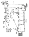
- the apparatus 30 includes a photoconductor 11 (e.g. a belt comprising a photoconductive insulator layer overlying a conductive layer on a support) having one or more image sectors adapted for movement along an operative path past primary charging station 12, exposure zones E 1 and E 2 , development stations 14-1, 14-2, 14-3 and 14-4 and transfer station 15.
- the corona charger at station 12, magnetic brushes at station 14 and transfer roller at station 15 can be of the various types known in the art and equivalent devices can be utilized.
- the apparatus 30 includes two exposure stations 13 and 23.
- the exposure station 13 includes means for supporting an original 0 1 (e.g. transparent platen 16) at the illumination zone of apparatus 30, a first illumination source 17 located between the illumination zone and the photoconductor 11 and second illumination source 18 located on the opposite side of the illumination zone from photoconductor 11.
- Lens means L 1 is provided to image the original 0 1 at the illumination zone onto the photoconductor 11 at exposure zone E 1 .
- a Fresnel-type field lens element (not shown) can be provided to image the transmission source 18 on the lens L 1 . (If the background area B is diffuse, the Fresnel lens is not needed; however, the source 18 should be of a higher intensity.)
- This preferred embodiment includes a half-tone screen 19 located in the optical path of lens L 1 and proximate the exposure zone.
- Apparatus 30 also comprises a second exposure station 23 constructed to expose a second component original 0 2 at a second exposure zone E 2 .
- Positioning structure 21 and 22 is provided respectively at exposure stations 13 and 23 to accurately locate originals on the exposure platens.
- a photoconductor location detector D and logic and control unit 35 are provided to coordinate exposure of component original 0 2 in register on a common photoconductor image sector with the electrostatic image of a first component original 0 1 (previously exposed on that photoconductor sector at station E 1 ).
- Station 23 includes a light-transmissive document platen 26, illumination sources 27 (e.g. xenon flash lamps) coupled to a power source P 3 , mirror 29 and lens means L 2 for imaging a component original 0 2 at exposure zone E 2 .
- illumination sources 27 e.g. xenon flash lamps
- the exposure procedure and structure of the present invention involve provision and use of originals 0 1 and O 2 of predetermined format.
- the original 0, comprises a light reflective continuous-tone area(s) C formed within a light-transmissive background area 8 1 .
- One preferred embodiment comprises photographic prints mounted on a light-transmissive plastic support.
- the component original O2 is predeterminedly constructed to cooperate with original component 0 1 , and for this purpose 0 2 has mask portions M which prevent source 27 illumination from passing to predetermined portions of exposure zone E 2 (viz. those portions which correspond to portions C of the original O 1 ).
- component original 0 2 is complementary to component original O 1 .
- the portions M can be light-absorptive (e.g. black) or light-transmissive.
- the background portions B 2 of component original 0 2 are desirably highly light-reflective (e.g. white) and line-type portions LT are light-absorptive (e.g. black).
- the illumination sources 27 can be on the opposite side of platen 26 from exposure zone E 2 and in such an embodiment the component original 0 2 can have light-reflective or opaque mask portions M, light-transmissive background portions B 2 and light-blocking line-type portions LT (e.g. black, light-reflective or light-scattering alphanumerics).
- the background portions B 1 of component original 0 1 can be light-absorptive rather than light-transmissive.
- the desired function is to mask (e.g. be non-reflective to) source 17 light and thus prevent it from passing to the photoconductor sector corresponding to portions B of original O 1 .
- a platen cover formed of light-absorptive material also could be used for this purpose.
- the exposure station 13 can function in two modes upon a photoconductor imate sector, which is first moved past the charging station 12 where it receives a uniform primary electrostatic charge.
- sources 17 and 18 are both actuated to illuminate the original 0 1 (which is in place on platen 16 with its light-reflective, continuous-tone portions facing the exposure zone E). More particularly, sources 17, e.g. xenon flash lamps are energized by power source P 1 at an intensity level selected for optimizing tone-scale of the electrostatic latent image formed on the photoconductor by light reflected from the continuous-tone portions C.
- a xenon flash tamp is energized by its power source P 2 to provide an exposure level at the photoconductor which substantially discharges portions of the photoconductor (corresponding to background B) by transmission exposure. That is, the intensity of this transmission exposure is selected to reduce the electrostatic charge level of portions corresponding to document background below the development level of the apparatus (e.g. to a level proximate or below the bias on magnetic brushes at development station).
- the discharge of transmission-exposed photoconductor portions therefore is preferably more than the maximum discharge (minimum development density level) of the reflection-exposed portions.
- the exposure from source 18 is selected to discharge the screen pattern in the background areas below the development level of the apparatus.
- continuous-tone photoconductor regions can be exposed at one of a plurality of preselectable levels (chosen to optimize tone-scale of the electrostatic image) and such continuous-tone exposure need not be concerned with the need for complete discharge in document background areas.
- This allows substantial improvement in the quality of electrophotographic reproductions of images which contain different content types like 0 1 ,
- the level of photoconductor exposure of the continuous-tone images can be varied in ways other than adjustment of the illumination intensity of source P i , e.g. such as by aperture adjustment and/or illumination time control.
- one skilled in the art may readily substitute other exposure techniques, e.g. scan exposure techniques, for the flash exposure system described with respect to Figure 1.
- the portions B of original 0 1 may desirably be selectively light-transmissive, light diffusive and/ or contain opaque line-type information.
- a graphic transparency image can be overlaid in a desired register with the original 0 1 , e.g. in register with a portion of background B.
- a photoconductor image sector is primary-charged at station 12, transported to exposure zone E 1 and exposed to component original 0 1 by sources 17 without transmission exposure by source 18.
- This provides a screened electrostatic latent image of the desired tone-scale on photoconductor sector portions corresponding to continuous-tone information areas C of component original 0 1 .
- the uniform primary charge remains on portions of the photoconductor sector that correspond to background portions B 1 of original O 1 .
- the photoconductor sector next moves to exposure zone E 2 ; and when it is in proper alignment with respect to exposure station 23 (as sensed by detector D), logic unit 35 effects a high-contrast exposure of that photoconductor image sector to cooperative component original 0 2 .
- sources 27 are energized and the photoconductor sector is exposed to O2 via lens L 2 and mirror 29 at a high exposure level.
- This forms a high-contrast, non- screened image of line-type information areas LT and, in addition, discharges the photoconductor image sector portions corresponding to background areas 8 2 (to a level below the development level of apparatus 20).
- the photoconductor image sector now bears the composite electrostatic image.
- Apparatus 30 also has structure which provide capabilities in regard to reproducing color originals.
- an array 31 of color filters e.g. including red, green and blue filters, is mounted along the optical path of exposure station 13.
- the array 31 is indexable by shaft 32 to selectively position each particular color filter in the optical path during the successive color-separation exposures of continuous-tone portions C of a color original 0 1 .
- the magnetic brush devices 14-1, 14-2, 14-3, 14-4, of the development station are operable, in response to signals from logic and control unit 35, to selectively apply different colors of toner (e.g. cyan, magenta, yellow and black toner) to different photoconductor image sectors.
- toner e.g. cyan, magenta, yellow and black toner
- component originals 0 1 and 0 2 are prepared and positioned at predetermined positions respectively on platens 16 and 26.
- component original 0 1 comprises a plurality of color continuous-tone information areas C (e.g. color prints) mounted on a light-transmissive support which forms background areas B 1 .
- the component original 0 2 for the Figure 1 embodiment comprises a light-reflective (e.g. white) background B 2 with black mask areas M located in register with areas C of component original 0 1 and with high-contrast, line-type information LT (e.g. black alphanumeric information) located in adjacent areas on the white support.
- Index or positioning means e.g.
- control data can include: (1) the desired operational mode (color or black-and-white), (2) desired number of reproductions and (3) special exposure level information regarding the respective color-separation exposures of composite original O 1 .
- the operator often will perform pre-runs of the color-separation exposures at varying levels to determinate optimum exposure levels for the particular pictorial information involved.
- Logic and control unit 35 preferably contains memory to store selected exposure levels for each respective color-separation exposure.
- a "run" command is actuated by the operator, and the photoconductor belt 11 moves successive photoconductor image sectors thereof past primary charger 12 and onto exposure zone E,.
- Position of the photoconductor image sectors is detected by a sensor, e.g. a detector D of perforations in the photoconductor, and a position signal is input to unit 35.
- Logic and control unit 35 effects control of successive red, green and blue color exposures onto successive photoconductor sectors.
- control from unit 35 can include synchronization of: (1) the indexing of filter array 31, (2) energization of power source P, at the desired level(s) and (3) energization of source P 2 to actuate background clean-up.
- the three photoconductor image sectors thus exposed, respectively comprise screened, continuous-tone red, green and blue color-separation electrostatic images corresponding to portions C of the original 0 1 and background portions discharged by source 18 to a level below the development level of apparatus 30 (e.g. below the bias level applied to the brushes of stations 14 by means not shown).
- the brush As the sector bearing the red color-separation electrostatic image moves over magnetic brush 14-1, the brush is activated by unit 35 to apply cyan toner in accordance with the electrostatic image.
- brushes 14-2 and 14-3 are activated to apply magenta and yellow toner respectively to the subsequent green and blue electrostatic color-separation images on successive sectors of the photoconductor.
- a panchromatic light exposure of selected tone-scale is effected by sources 17, without the activation of source 18. It may be preferred to filter this exposure, e.g. with another element of array 31, to achieve a more panchromatic system response for this exposure.
- the electrostatic pattern on the fourth photoconductor image sector includes a screened, continuous-tone latent image pattern of the pictorial areas C and uniform primary charge on other areas corresponding to background 81,
- the fourth sector moves next to exposure zone E 2 , and, in proper timed relation with movement of belt 11, unit 35 activates sources 27 to effect a high-contrast exposure of component original 0 2 , in register with the image of component original 0 1 , onto the fourth sector.
- the electrostatic image on the fourth sector leaving zone E 2 thus comprises (1) the continuous-tone electrostatic image component exposed at zone E 1 (and undisturbed by the zone E 2 exposure because of mask portions M on original 0 2 ), (2) the high-contrast, unscreened, alphanumeric electrostatic patterns corresponding to areas LT of composite original 0 2 and (3) the clean background portions discharged below the development level.
- the fourth sector subsequently is developed with black toner by magnetic brush 14-4.
- logic and control unit 35 can be constructed to effect the above-described exposures of the four photoconductor image sectors in any desired sequence.
- logic and control can effect exposures so that the line information is in a color(s) other than black.
- cyan line information can be provided by omitting the source 18 illumination and providing source 27 illumination to the red filter exposed image sector rather than the neutral density exposed sector.
- the apparatus 30 can employ less than four colors, if desired.
- unit 35 After exposure and development and in proper timed relation with movement of the photoconductor image sectors to transfer station 15, unit 35 signals actuation for feeding a copy sheet S to the transfer roller. Successive cyan, magenta, yellow and black toner images are then transferred to the copy sheet, in register, by the first, second, third and fourth image sectors of the photoconductor 11. Unit 35 then signals pick-off of the copy sheet by detack device 39, and copy sheet S is fed through fixing device F to a receiver bin. It will be appreciated that the successive reproductions of the composite original can be made in a continuous mode by repeating the above-described operation as the belt recirculates. Appropriate photoconductor cleaning and rejuvination (known in the art) can be provided along the return path from station 15 to station 12.
- Apparatus 30 also can be operated in a black-and-white copy mode.
- appropriate control information is input to unit 35, e.g. to select the black-and-white mode, the number of copies desired and any exposure level information for sources 17.
- Start of the copy run is commanded and control unit 35 effects repeated cycles of charge exposure and development as described above with respect to the fourth (black toner) sector on successive photoconductor image sectors.
- Copy sheet feed in this mode is activated for each photoconductor image sector, in contrast to the color mode where four toner images are transferred between each copy sheet detack and replacement cycle.
- Figure 2 discloses another embodiment of electrophotographic apparatus 40 in accord with the present invention.
- Apparatus 40 is similar in functional capabilities to the Figure 1 apparatus, and again, corresponding structural features are indicated with corresponding designators.
- the apparatus 40 differs from the Figure 1 embodiment primarily with respect to the construction of the photoconductor image sectors and the operative path of the apparatus. Specifically, the photoconductor image sectors of apparatus 40 are in discrete sheet form and have separate paths within the development portion of the apparatus.
- originals 0 1 and O2 are prepared as described with respect to Figure 3 and placed in register on platens 16 and 26.
- Appropriate control signals are input to a control and logic unit (not shown) and a start command is actuated.
- a first sheet sector 11-1 then is fed from a supply, primary-charged and exposed by device 13 via a red filter to original 0 1 at zone E 1 (in the same manner described with respect to the first photoconductor image sector of the belt 11 of apparatus 30).
- the sheet 11-1 next is moved past exposure station 23 (without an exposure actuation), is developed by brush 14-1 with cyan toner and is moved to hold position P i .
- the present invention provides a method which produces electrophotographic reproductions having screened, continuous-tone color portions, clean background areas and high contrast line information, and which is characterized by the capability to selectively vary the color in which line information is reproduced, without changing the original input.
- the apparatus constitutions of the present invention provide simple yet highly productive structures for achieving such desirable capabilities.
Landscapes
- Physics & Mathematics (AREA)
- General Physics & Mathematics (AREA)
- Color Electrophotography (AREA)
- Control Or Security For Electrophotography (AREA)
- Exposure Or Original Feeding In Electrophotography (AREA)
Claims (4)
dadurch gekennzeichnet, daß die erste Belichtungseinrichtung (1) Mittel enthält, mit denen die Fotoleiterabschnitte bei Belichtungsstärken, die für eine Reproduktion mit abgestufter Tonwertskala optimiert sind, bildmäßig mit Halbtonbereichen (C) einer ersten Teilbildvorlage (01) an dem ersten Vorlagenhalter (16) belichtet werden,
sowie (2) eine Einrichtung (P2, 18) mit der eine Hintergrundbelichtung anderer Teile der Fotoleiterabschnitte, die den mit Halbtonbereichen belichteten Abschnitten benachbart sind, mit einer Belichtungsstärke vorgenommen wird, die zu einer Entladung dieser anderen Teile unterhalb eines vorbestimmten Entwicklungsniveaus führt, und daß die Steuereinrichtung (35) sowohl die (i) Einrichtung für die bildmäßige Belichtung (P1, 17) als auch die Einrichtung für die Hintergrundbelichtung (P2, 18) in Bezug auf mindestens einen der Fotoletierabschnitte aktiviert und (ii) die Einrichtung für die bildmäßige Belichtung (P1, 17) und die zweite Belichtungseinrichtung (P3, 27, L2) in Bezug auf einen anderen der Fotoleiterabschnitte aktiviert.
Applications Claiming Priority (2)
| Application Number | Priority Date | Filing Date | Title |
|---|---|---|---|
| US493868 | 1983-05-12 | ||
| US06/493,868 US4472047A (en) | 1983-05-12 | 1983-05-12 | Apparatus and method for electrophotographically producing copy having continuous-tone and other content |
Publications (2)
| Publication Number | Publication Date |
|---|---|
| EP0141850A1 EP0141850A1 (de) | 1985-05-22 |
| EP0141850B1 true EP0141850B1 (de) | 1989-04-19 |
Family
ID=23962031
Family Applications (3)
| Application Number | Title | Priority Date | Filing Date |
|---|---|---|---|
| EP84902133A Expired EP0141851B1 (de) | 1983-05-12 | 1984-05-03 | Vorrichtung und verfahren zur erzeugung von kopien die feine unterschiede in tönung haben |
| EP84902134A Expired EP0142550B1 (de) | 1983-05-12 | 1984-05-03 | Vorrichtung und verfahren zur elektrophotographischen herstellung einer kopie mit kontinuierlichen tönen und sonstigen |
| EP84902132A Expired EP0141850B1 (de) | 1983-05-12 | 1984-05-03 | Vorrichtung und verfahren zur erzeugung von elektrophotografischen farbigen kopien die feine unterschiede in tönung und anderen inhalten verschiedener farben haben |
Family Applications Before (2)
| Application Number | Title | Priority Date | Filing Date |
|---|---|---|---|
| EP84902133A Expired EP0141851B1 (de) | 1983-05-12 | 1984-05-03 | Vorrichtung und verfahren zur erzeugung von kopien die feine unterschiede in tönung haben |
| EP84902134A Expired EP0142550B1 (de) | 1983-05-12 | 1984-05-03 | Vorrichtung und verfahren zur elektrophotographischen herstellung einer kopie mit kontinuierlichen tönen und sonstigen |
Country Status (6)
| Country | Link |
|---|---|
| US (1) | US4472047A (de) |
| EP (3) | EP0141851B1 (de) |
| JP (3) | JPS60501275A (de) |
| CA (1) | CA1218105A (de) |
| DE (3) | DE3477853D1 (de) |
| WO (3) | WO1984004607A1 (de) |
Families Citing this family (24)
| Publication number | Priority date | Publication date | Assignee | Title |
|---|---|---|---|---|
| US4537490A (en) * | 1983-05-12 | 1985-08-27 | Eastman Kodak Company | Apparatus and method for electrophotographically producing copy having continuous-tone and other content |
| US4794421A (en) | 1983-05-12 | 1988-12-27 | Eastman Kodak Company | Apparatus and method for electrophotographically producing copies from originals having continuous-tone and other content |
| DE3517397C2 (de) * | 1984-05-15 | 1997-04-10 | Canon Kk | Elektrofotografisches Kopiergerät |
| WO1986002745A1 (fr) * | 1984-10-22 | 1986-05-09 | Konishiroku Photo Industry Co., Ltd. | Procede et appareil pour la formation d'images multicolores |
| US4712907A (en) * | 1985-11-01 | 1987-12-15 | Xerox Corporation | Sequencing means for photocopying processes |
| WO1987003707A1 (en) * | 1985-12-16 | 1987-06-18 | Eastman Kodak Company | Copying apparatus and method with editing and production control capability |
| US4791450A (en) * | 1985-12-16 | 1988-12-13 | Eastman Kodak Company | Multicolor electrophotographic reproduction apparatus and method for producing color accented copies |
| US4740818A (en) * | 1985-12-16 | 1988-04-26 | Eastman Kodak Company | Electrophotographic reproduction apparatus and method with selective screening |
| EP0250556B1 (de) * | 1985-12-16 | 1991-05-29 | EASTMAN KODAK COMPANY (a New Jersey corporation) | Elektrophotographisches mehrfarbenbilderzeugungsgerät und verfahren zur herstellung von kopien mit hervorhebung der farben |
| WO1987003709A1 (en) * | 1985-12-16 | 1987-06-18 | Eastman Kodak Company | Electrophotographic reproduction apparatus and method with selective screening |
| US4777510A (en) * | 1986-12-11 | 1988-10-11 | Eastman Kodak Company | Copying apparatus and method with editing and production control capability |
| JPH0690562B2 (ja) * | 1985-12-28 | 1994-11-14 | 株式会社リコー | カラ−複写機 |
| US4998131A (en) * | 1987-04-03 | 1991-03-05 | Brother Kogyo Kabushiki Kaisha | Method and apparatus for recording image data in multiplexed manner |
| US4845524A (en) * | 1987-06-03 | 1989-07-04 | Minolta Camera Kabushiki Kaisha | Image forming method |
| JPH01156766A (ja) * | 1987-12-15 | 1989-06-20 | Canon Inc | 画像形成装置 |
| EP0369429B1 (de) * | 1988-11-16 | 1994-09-14 | Canon Kabushiki Kaisha | Aufnahmegerät mit mehreren Entwicklungseinheiten |
| US5204729A (en) * | 1990-01-23 | 1993-04-20 | Sharp Kabushiki Kaisha | Full color copying machine |
| US5140348A (en) * | 1990-09-28 | 1992-08-18 | Eastman Kodak Company | Color image production apparatus with border color selection |
| DE69206163T2 (de) * | 1991-02-01 | 1996-07-04 | Sharp Kk | Elektrofotographische Vorrichtung. |
| US5138366A (en) * | 1991-05-23 | 1992-08-11 | Eastman Kodak Company | Method of printing color borders with color prints and prints with integral borders |
| US5760882A (en) * | 1996-06-20 | 1998-06-02 | Eastman Kodak Company | Contact printer and method of making a filter for a contact printer |
| US5856864A (en) * | 1996-06-20 | 1999-01-05 | Eastman Kodak Company | Photographic printer and method of making a filter for a photographic printer |
| US5786902A (en) * | 1996-09-17 | 1998-07-28 | Eastman Kodak Company | Photographic printer and method of digitally correcting for a photographic printer |
| JP5062243B2 (ja) * | 2009-12-16 | 2012-10-31 | パナソニック株式会社 | スクリーン印刷システム及びスクリーン印刷システムのマスクのクリーニング方法 |
Family Cites Families (19)
| Publication number | Priority date | Publication date | Assignee | Title |
|---|---|---|---|---|
| BE494901A (de) * | 1947-06-16 | |||
| US2665984A (en) * | 1950-02-27 | 1954-01-12 | Tourneau Frank P Le | Method for making combined line and halftone negatives |
| US3547533A (en) * | 1965-11-04 | 1970-12-15 | Xerox Corp | Microfilm reproduction machine |
| US3523725A (en) * | 1968-05-01 | 1970-08-11 | Xerox Corp | Xerographic reproducing apparatus |
| US3615392A (en) * | 1968-05-02 | 1971-10-26 | Xerox Corp | Electrophotographic reproduction of originals containing both multicolor and line areas |
| US3576367A (en) * | 1968-09-06 | 1971-04-27 | Ibm | Machine for preparing documents |
| US3724943A (en) * | 1969-06-04 | 1973-04-03 | Xerox Corp | Color reproduction apparatus |
| US3620618A (en) * | 1969-10-08 | 1971-11-16 | Xerox Corp | Multiple input copying apparatus |
| US3728018A (en) * | 1969-11-14 | 1973-04-17 | Xerox Corp | Imaging apparatus |
| US3825338A (en) * | 1972-10-12 | 1974-07-23 | Addressograph Multigraph | Optical system with selectable feeds |
| US4045218A (en) * | 1974-03-29 | 1977-08-30 | Xerox Corporation | Method for electrostatically producing a color accented photocopy |
| US4027962A (en) * | 1975-01-13 | 1977-06-07 | Xerox Corporation | Color transparency reproducing machine |
| US3970042A (en) * | 1975-01-17 | 1976-07-20 | Xerox Corporation | Color development apparatus |
| US4066351A (en) * | 1976-02-20 | 1978-01-03 | Xerox Corporation | Variable illumination optical system |
| US4043656A (en) * | 1976-03-03 | 1977-08-23 | Xerox Corporation | Transparency copying machine |
| US4083632A (en) * | 1976-04-05 | 1978-04-11 | Xerox Corporation | Multi-frequency screen |
| US4111542A (en) * | 1977-04-27 | 1978-09-05 | Xerox Corporation | Collating system for opaque documents and slide reproductions |
| US4256820A (en) * | 1978-05-22 | 1981-03-17 | Savin Corporation | Method of electrophotography using low intensity exposive |
| US4255040A (en) * | 1978-07-20 | 1981-03-10 | Xerox Corporation | Positive overlay electronic xerographic printer |
-
1983
- 1983-05-12 US US06/493,868 patent/US4472047A/en not_active Expired - Fee Related
-
1984
- 1984-05-03 JP JP59501879A patent/JPS60501275A/ja active Pending
- 1984-05-03 JP JP59501873A patent/JPS60501274A/ja active Pending
- 1984-05-03 DE DE8484902134T patent/DE3477853D1/de not_active Expired
- 1984-05-03 EP EP84902133A patent/EP0141851B1/de not_active Expired
- 1984-05-03 DE DE8484902132T patent/DE3477852D1/de not_active Expired
- 1984-05-03 DE DE8484902133T patent/DE3474221D1/de not_active Expired
- 1984-05-03 WO PCT/US1984/000667 patent/WO1984004607A1/en not_active Ceased
- 1984-05-03 WO PCT/US1984/000666 patent/WO1984004605A1/en not_active Ceased
- 1984-05-03 JP JP59501981A patent/JPS60501279A/ja active Pending
- 1984-05-03 EP EP84902134A patent/EP0142550B1/de not_active Expired
- 1984-05-03 EP EP84902132A patent/EP0141850B1/de not_active Expired
- 1984-05-03 WO PCT/US1984/000668 patent/WO1984004606A1/en not_active Ceased
- 1984-05-07 CA CA000453702A patent/CA1218105A/en not_active Expired
Also Published As
| Publication number | Publication date |
|---|---|
| JPS60501279A (ja) | 1985-08-08 |
| EP0141850A1 (de) | 1985-05-22 |
| WO1984004605A1 (en) | 1984-11-22 |
| US4472047A (en) | 1984-09-18 |
| EP0142550B1 (de) | 1989-04-19 |
| EP0141851A1 (de) | 1985-05-22 |
| WO1984004606A1 (en) | 1984-11-22 |
| EP0142550A1 (de) | 1985-05-29 |
| JPS60501275A (ja) | 1985-08-08 |
| DE3477853D1 (en) | 1989-05-24 |
| CA1218105A (en) | 1987-02-17 |
| WO1984004607A1 (en) | 1984-11-22 |
| DE3474221D1 (en) | 1988-10-27 |
| JPS60501274A (ja) | 1985-08-08 |
| EP0141851B1 (de) | 1988-09-21 |
| DE3477852D1 (en) | 1989-05-24 |
Similar Documents
| Publication | Publication Date | Title |
|---|---|---|
| EP0141850B1 (de) | Vorrichtung und verfahren zur erzeugung von elektrophotografischen farbigen kopien die feine unterschiede in tönung und anderen inhalten verschiedener farben haben | |
| US4794421A (en) | Apparatus and method for electrophotographically producing copies from originals having continuous-tone and other content | |
| JPH0652445B2 (ja) | カラープリント作成方法 | |
| US4791450A (en) | Multicolor electrophotographic reproduction apparatus and method for producing color accented copies | |
| US4537490A (en) | Apparatus and method for electrophotographically producing copy having continuous-tone and other content | |
| SU822771A3 (ru) | Электрофотографический аппарат дл МНОгОцВЕТНОгО КОпиРОВАНи | |
| CA1222020A (en) | Apparatus and method for forming multicolor electrophotographic images | |
| US5055886A (en) | Image forming apparatus capable of forming copied images edited from an original image | |
| US4750017A (en) | Composite copying method and color copier for practicing the same | |
| US5038171A (en) | Multicolored image forming method and apparatus therefor | |
| EP0250556B1 (de) | Elektrophotographisches mehrfarbenbilderzeugungsgerät und verfahren zur herstellung von kopien mit hervorhebung der farben | |
| US4942427A (en) | Method and apparatus for annotating electrophotographic prints of photographic negatives | |
| US5010366A (en) | Slide transparency projector apparatus for use with an electrophotographic reproduction machine | |
| US5065199A (en) | Obtaining color balance for optical copiers by setting the exposure and primary voltage for each color | |
| US5019866A (en) | Pressurized screen assembly for exposure of a continuous tone image | |
| JPH01293363A (ja) | 画像形成装置 | |
| EP0301576B1 (de) | Bilderzeugungsgerät | |
| JPS60237469A (ja) | 画像形成装置 | |
| JPS6263951A (ja) | 多色電子写真複写装置 | |
| JPS62215279A (ja) | カラ−電子複写装置 | |
| JPS60102660A (ja) | カラ−複写装置 | |
| JPH0527543A (ja) | 画像形成装置 | |
| JPH0414064A (ja) | カラー複写機 | |
| JPS63271367A (ja) | 画像形成装置 | |
| JPH07319224A (ja) | 静電印刷システム |
Legal Events
| Date | Code | Title | Description |
|---|---|---|---|
| PUAI | Public reference made under article 153(3) epc to a published international application that has entered the european phase |
Free format text: ORIGINAL CODE: 0009012 |
|
| AK | Designated contracting states |
Designated state(s): DE FR GB |
|
| 17P | Request for examination filed |
Effective date: 19850502 |
|
| 17Q | First examination report despatched |
Effective date: 19870305 |
|
| GRAA | (expected) grant |
Free format text: ORIGINAL CODE: 0009210 |
|
| AK | Designated contracting states |
Kind code of ref document: B1 Designated state(s): DE FR GB |
|
| REF | Corresponds to: |
Ref document number: 3477852 Country of ref document: DE Date of ref document: 19890524 |
|
| ET | Fr: translation filed | ||
| PLBE | No opposition filed within time limit |
Free format text: ORIGINAL CODE: 0009261 |
|
| STAA | Information on the status of an ep patent application or granted ep patent |
Free format text: STATUS: NO OPPOSITION FILED WITHIN TIME LIMIT |
|
| 26N | No opposition filed | ||
| PGFP | Annual fee paid to national office [announced via postgrant information from national office to epo] |
Ref country code: GB Payment date: 19920428 Year of fee payment: 9 |
|
| PGFP | Annual fee paid to national office [announced via postgrant information from national office to epo] |
Ref country code: FR Payment date: 19920512 Year of fee payment: 9 |
|
| PGFP | Annual fee paid to national office [announced via postgrant information from national office to epo] |
Ref country code: DE Payment date: 19920522 Year of fee payment: 9 |
|
| PG25 | Lapsed in a contracting state [announced via postgrant information from national office to epo] |
Ref country code: GB Effective date: 19930503 |
|
| GBPC | Gb: european patent ceased through non-payment of renewal fee |
Effective date: 19930503 |
|
| PG25 | Lapsed in a contracting state [announced via postgrant information from national office to epo] |
Ref country code: FR Effective date: 19940131 |
|
| PG25 | Lapsed in a contracting state [announced via postgrant information from national office to epo] |
Ref country code: DE Effective date: 19940201 |
|
| REG | Reference to a national code |
Ref country code: FR Ref legal event code: ST |