EP0141877B1 - Vanne thermostatique - Google Patents
Vanne thermostatique Download PDFInfo
- Publication number
- EP0141877B1 EP0141877B1 EP83111498A EP83111498A EP0141877B1 EP 0141877 B1 EP0141877 B1 EP 0141877B1 EP 83111498 A EP83111498 A EP 83111498A EP 83111498 A EP83111498 A EP 83111498A EP 0141877 B1 EP0141877 B1 EP 0141877B1
- Authority
- EP
- European Patent Office
- Prior art keywords
- valve
- branch circuit
- heating circulation
- control device
- temperature sensor
- Prior art date
- Legal status (The legal status is an assumption and is not a legal conclusion. Google has not performed a legal analysis and makes no representation as to the accuracy of the status listed.)
- Expired
Links
Images

Classifications
-
- F—MECHANICAL ENGINEERING; LIGHTING; HEATING; WEAPONS; BLASTING
- F24—HEATING; RANGES; VENTILATING
- F24D—DOMESTIC- OR SPACE-HEATING SYSTEMS, e.g. CENTRAL HEATING SYSTEMS; DOMESTIC HOT-WATER SUPPLY SYSTEMS; ELEMENTS OR COMPONENTS THEREFOR
- F24D19/00—Details
- F24D19/10—Arrangement or mounting of control or safety devices
- F24D19/1006—Arrangement or mounting of control or safety devices for water heating systems
- F24D19/1009—Arrangement or mounting of control or safety devices for water heating systems for central heating
- F24D19/1015—Arrangement or mounting of control or safety devices for water heating systems for central heating using a valve or valves
-
- G—PHYSICS
- G05—CONTROLLING; REGULATING
- G05D—SYSTEMS FOR CONTROLLING OR REGULATING NON-ELECTRIC VARIABLES
- G05D23/00—Control of temperature
- G05D23/01—Control of temperature without auxiliary power
- G05D23/02—Control of temperature without auxiliary power with sensing element expanding and contracting in response to changes of temperature
-
- G—PHYSICS
- G05—CONTROLLING; REGULATING
- G05D—SYSTEMS FOR CONTROLLING OR REGULATING NON-ELECTRIC VARIABLES
- G05D23/00—Control of temperature
- G05D23/19—Control of temperature characterised by the use of electric means
- G05D23/30—Automatic controllers with an auxiliary heating device affecting the sensing element, e.g. for anticipating change of temperature
Definitions
- the present invention relates to a thermostatic valve according to the preamble of claim 1.
- thermoelectric valve so that the temperature sensor of the valve can be given an increased temperature without this increased temperature having to be generated constantly from an auxiliary electrical energy.
- a housing surrounding the expansion body has a plurality of air passage openings which can be closed by a slide.
- This housing is thermally conductively connected to the heating water supply via a heat conducting bar.
- the control takes place via the slide by means of its battery-powered drive, while the valve adjustment is effected by means of the energy which is drawn from the heating water supply.
- the preamble of claim 1 is known from GB-A-313 916.
- the heating device shown in FIG. 1 shows the control of a valve via an outside temperature sensor, a branch line being connected behind the valve, via which the outside temperature sensor is only heated when the valve is open.
- this subordinate control has the effect that, for example, overheating is avoided in the front car of a train where the steam is still very hot, while in the rear car the larger heat of the valve takes into account the decreasing heat of the steam becomes.
- the object of the present invention is to extract the energy required for increasing the temperature of the temperature sensor from the heating circuit via a branch line (bypass) in such a way that the electrical auxiliary energy is only required for one switching operation.
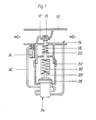
- a valve seat 12 is arranged in a thermostatic valve lower part 10.
- a valve spindle 14 is led out of the lower part 10 in a sealed manner and carries a closing body 16 at its end projecting into the lower part 10.
- a spring 18 is supported on the one hand on the lower part 10 and on the other hand on a stop 20 connected to the valve spindle 14, whereby the valve 12/16 is normally held in the open position.
- An upper part 22 is screwed to the lower part 10.
- a temperature sensor 24 is supported with its housing 26 in the upper part 22, its working piston 28 being supported on the valve spindle 14 via an elastic intermediate member 30.
- a branch line (bypass) 32 is connected to the lower part 10 or to the heating circuit in front of and behind the lower part. It is only essential that the branch line is connected in front of and behind the valve 12/16. Furthermore, a pilot valve 34 is arranged in the branch line 32, via which the passage of the heating medium through the branch line 32 can be opened and blocked. The branch line 32 is guided past the temperature sensor 24, so that heat exchange takes place when the pilot valve 34 is open and the temperature sensor 24 is heated and the valve 12/16 closes.
- connection of the branch line 32 in the manner shown is not absolutely necessary. Rather, an aperture, ie a constriction in the tubing or in the lower part 10 are arranged so that a pressure difference between the space in front and behind the diaphragm is generated.
- the branch line 32 can then be connected to the space in front of and behind the panel. This solution also provides frost protection, since in this case a minimum flow through the valve 12/16 is required to generate the pressure drop.
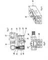
- the branch line 32 is arranged below the thermostatic valve 10, 22, so that the rising warm air can act on the temperature sensor 24 through slots in the upper part 22.
- a module 36 which can be flanged onto the lower part 10 contains a programmable control in the form of a microprocessor 38, a voltage supply by means of built-in batteries 50, certain operating and programming elements 40 and a digital clock 42.
- the microprocessor 38 controls a magnetic coil 44 which is actuated by a spring 46 acts piston 48 held in the closed position and can bring this into the open position when energized. 5, when the solenoid 44 is briefly excited, the piston 48, which is designed as a core, is drawn into the latter.
- a pin 52 fixed to the housing grips through a link path 54 in the piston 48, so that when the magnet coil 44 is subsequently de-energized, the piston 48 assumes the opening position shown in FIG. 6. No energy is therefore required to hold the piston 48 in the open position.
Landscapes
- Engineering & Computer Science (AREA)
- Physics & Mathematics (AREA)
- General Physics & Mathematics (AREA)
- Automation & Control Theory (AREA)
- Thermal Sciences (AREA)
- Chemical & Material Sciences (AREA)
- Combustion & Propulsion (AREA)
- Mechanical Engineering (AREA)
- General Engineering & Computer Science (AREA)
- Temperature-Responsive Valves (AREA)
- Control Of Temperature (AREA)
- Details Of Valves (AREA)
Claims (7)
Priority Applications (3)
| Application Number | Priority Date | Filing Date | Title |
|---|---|---|---|
| EP83111498A EP0141877B1 (fr) | 1983-11-17 | 1983-11-17 | Vanne thermostatique |
| DE8383111498T DE3376772D1 (en) | 1983-11-17 | 1983-11-17 | Thermostatic valve |
| AT83111498T ATE34628T1 (de) | 1983-11-17 | 1983-11-17 | Thermostatventil. |
Applications Claiming Priority (1)
| Application Number | Priority Date | Filing Date | Title |
|---|---|---|---|
| EP83111498A EP0141877B1 (fr) | 1983-11-17 | 1983-11-17 | Vanne thermostatique |
Publications (2)
| Publication Number | Publication Date |
|---|---|
| EP0141877A1 EP0141877A1 (fr) | 1985-05-22 |
| EP0141877B1 true EP0141877B1 (fr) | 1988-05-25 |
Family
ID=8190812
Family Applications (1)
| Application Number | Title | Priority Date | Filing Date |
|---|---|---|---|
| EP83111498A Expired EP0141877B1 (fr) | 1983-11-17 | 1983-11-17 | Vanne thermostatique |
Country Status (3)
| Country | Link |
|---|---|
| EP (1) | EP0141877B1 (fr) |
| AT (1) | ATE34628T1 (fr) |
| DE (1) | DE3376772D1 (fr) |
Cited By (1)
| Publication number | Priority date | Publication date | Assignee | Title |
|---|---|---|---|---|
| CN105204549A (zh) * | 2015-10-23 | 2015-12-30 | 无锡溥汇机械科技有限公司 | 一种自控式恒温装置 |
Families Citing this family (3)
| Publication number | Priority date | Publication date | Assignee | Title |
|---|---|---|---|---|
| GB8624463D0 (en) * | 1986-10-13 | 1986-11-19 | Pidgeon S M | Radiator valves |
| WO1990004136A1 (fr) * | 1988-10-07 | 1990-04-19 | Grässlin KG | Dispositif de fixation pour logements modulaires de dispositifs de commande electriques et/ou electroniques montes a l'exterieur de pompes, soupapes ou similaires, notamment pour la construction d'installations de chauffage |
| KR100834677B1 (ko) * | 2006-01-16 | 2008-06-02 | 삼성전자주식회사 | 주파수 분할 다중접속 방식의 무선 통신 시스템에서 자원할당 장치 및 방법 |
Family Cites Families (3)
| Publication number | Priority date | Publication date | Assignee | Title |
|---|---|---|---|---|
| GB313916A (en) * | 1928-06-19 | 1930-09-01 | Compagnie National Des Radiateurs | Improvements in the thermostatic control of heat radiators |
| DE1798294B2 (de) * | 1968-09-21 | 1973-02-08 | Elektrische sollwert-einstellvorrichtung fuer thermostaten | |
| DE3125051A1 (de) * | 1981-06-26 | 1983-01-13 | Peter-Uhren Gmbh, 7210 Rottweil | System zur regelung und registrierung von heizenergie |
-
1983
- 1983-11-17 EP EP83111498A patent/EP0141877B1/fr not_active Expired
- 1983-11-17 AT AT83111498T patent/ATE34628T1/de not_active IP Right Cessation
- 1983-11-17 DE DE8383111498T patent/DE3376772D1/de not_active Expired
Cited By (1)
| Publication number | Priority date | Publication date | Assignee | Title |
|---|---|---|---|---|
| CN105204549A (zh) * | 2015-10-23 | 2015-12-30 | 无锡溥汇机械科技有限公司 | 一种自控式恒温装置 |
Also Published As
| Publication number | Publication date |
|---|---|
| DE3376772D1 (en) | 1988-06-30 |
| ATE34628T1 (de) | 1988-06-15 |
| EP0141877A1 (fr) | 1985-05-22 |
Similar Documents
| Publication | Publication Date | Title |
|---|---|---|
| DE3516502A1 (de) | Temperaturregeleinrichtung fuer das kuehlmittel von brennkraftmaschinen | |
| DE408443C (de) | Vorrichtung zur Regelung elektrisch gesteuerter Thermostaten fuer elektrisch beheizte Apparate | |
| EP0141877A1 (fr) | Vanne thermostatique | |
| EP0149450B1 (fr) | Conditionneur d'air pour véhicules ferroviaires | |
| EP0791159B1 (fr) | Appareil pour le chauffage d'eau de chauffage et d'eau sanitaire | |
| DE658117C (de) | Einrichtung zur selbsttaetigen Regelung von Luftheizungen, insbesondere fuer Eisenbahnfahrzeuge | |
| DE1906553A1 (de) | Steuer- und Regeleinrichtung fuer elektrische Speicheroefen | |
| DE3018237A1 (de) | Heizkoerperventil mit einem thermostaten | |
| EP0113013B1 (fr) | Appareil pour soupapes thermostatiques, notamment pour chute de température de corps de chauffe commandés par thermostat | |
| DE20108789U1 (de) | Verteilervorrichtung für einen mit einem fließfähigen Medium betriebenen Kreislauf, insbesondere eine Heiz- oder Kühlanlage | |
| DE3227147A1 (de) | Temperaturregelsystem fuer zentralheizungen | |
| DE3149760A1 (de) | Vorrichtung zur zeitabhaengigen steuerung des heizmitteldurchsatzes von heizkoerpern | |
| DE939343C (de) | Mit einer Temperaturregeleinrichtung vereinigter Stufenschalter fuer elektrisch beheizte Geraete | |
| DE920095C (de) | Waermetechnisches Kuechengeraet | |
| DE674197C (de) | Umstellvorrichtung zur Abkuerzung der Anheizzeit bei einer Umlaufdampfheizung fuer Eisenbahnwagen mit selbsttaetiger zweistufiger Temperaturregelung | |
| DE718483C (de) | Regleranordnung zur Temperaturregelung eines von einer Heizanlage beheizten Raumes | |
| DE720417C (de) | Elektrisch betriebene Warmwasserheizungsanlage mit einem durch eingebaute Widerstaende beheizten Warmwasserspeicher | |
| DE2755602A1 (de) | Heizungseinrichtung mit gasbefeuertem heizkessel | |
| DE688917C (de) | Steuerung fuer Kompressionskaeltemaschinen | |
| DE2128291B2 (de) | Vorrichtung zur regelung der temperatur von brauchwasser aus einem gasheizgeraet | |
| AT217597B (fr) | ||
| DE1226765B (de) | Selbsttaetige, elektrisch gesteuerte Gaszufuhrregelvorrichtung fuer einen als Waermeerzeuger einer Pumpen-Sammelheizungs-anlage dienenden gasbeheizten Durchlauferhitzer mit Wassermangelsicherung | |
| DE2949300A1 (de) | Temperaturabhaengig arbeitender regler | |
| DE19702686A1 (de) | Gasbeheizter Warmwasserbereiter | |
| DE1101644B (de) | Energieregler fuer elektrische Heizgeraete mit Mitteln zur Ausschaltung des Raumtemperatureinflusses |
Legal Events
| Date | Code | Title | Description |
|---|---|---|---|
| PUAI | Public reference made under article 153(3) epc to a published international application that has entered the european phase |
Free format text: ORIGINAL CODE: 0009012 |
|
| 17P | Request for examination filed |
Effective date: 19841112 |
|
| AK | Designated contracting states |
Designated state(s): AT BE CH DE FR GB IT LI NL SE |
|
| 17Q | First examination report despatched |
Effective date: 19870609 |
|
| GRAA | (expected) grant |
Free format text: ORIGINAL CODE: 0009210 |
|
| AK | Designated contracting states |
Kind code of ref document: B1 Designated state(s): AT BE CH DE FR GB IT LI NL SE |
|
| REF | Corresponds to: |
Ref document number: 34628 Country of ref document: AT Date of ref document: 19880615 Kind code of ref document: T |
|
| REF | Corresponds to: |
Ref document number: 3376772 Country of ref document: DE Date of ref document: 19880630 |
|
| ET | Fr: translation filed | ||
| GBT | Gb: translation of ep patent filed (gb section 77(6)(a)/1977) | ||
| ITF | It: translation for a ep patent filed | ||
| ITTA | It: last paid annual fee | ||
| PLBE | No opposition filed within time limit |
Free format text: ORIGINAL CODE: 0009261 |
|
| STAA | Information on the status of an ep patent application or granted ep patent |
Free format text: STATUS: NO OPPOSITION FILED WITHIN TIME LIMIT |
|
| 26N | No opposition filed | ||
| PGFP | Annual fee paid to national office [announced via postgrant information from national office to epo] |
Ref country code: FR Payment date: 19890918 Year of fee payment: 7 |
|
| PGFP | Annual fee paid to national office [announced via postgrant information from national office to epo] |
Ref country code: SE Payment date: 19890922 Year of fee payment: 7 |
|
| PGFP | Annual fee paid to national office [announced via postgrant information from national office to epo] |
Ref country code: CH Payment date: 19890926 Year of fee payment: 7 |
|
| PGFP | Annual fee paid to national office [announced via postgrant information from national office to epo] |
Ref country code: GB Payment date: 19890930 Year of fee payment: 7 |
|
| PG25 | Lapsed in a contracting state [announced via postgrant information from national office to epo] |
Ref country code: DE Effective date: 19891024 |
|
| PG25 | Lapsed in a contracting state [announced via postgrant information from national office to epo] |
Ref country code: AT Effective date: 19891117 |
|
| PGFP | Annual fee paid to national office [announced via postgrant information from national office to epo] |
Ref country code: BE Payment date: 19891117 Year of fee payment: 7 |
|
| PGFP | Annual fee paid to national office [announced via postgrant information from national office to epo] |
Ref country code: NL Payment date: 19891130 Year of fee payment: 7 |
|
| PG25 | Lapsed in a contracting state [announced via postgrant information from national office to epo] |
Ref country code: GB Effective date: 19901117 |
|
| PG25 | Lapsed in a contracting state [announced via postgrant information from national office to epo] |
Ref country code: SE Effective date: 19901118 |
|
| PG25 | Lapsed in a contracting state [announced via postgrant information from national office to epo] |
Ref country code: LI Effective date: 19901130 Ref country code: CH Effective date: 19901130 Ref country code: BE Effective date: 19901130 |
|
| BERE | Be: lapsed |
Owner name: HONEYWELL-BRAUKMANN G.M.B.H. Effective date: 19901130 |
|
| PG25 | Lapsed in a contracting state [announced via postgrant information from national office to epo] |
Ref country code: NL Effective date: 19910601 |
|
| NLV4 | Nl: lapsed or anulled due to non-payment of the annual fee | ||
| GBPC | Gb: european patent ceased through non-payment of renewal fee | ||
| PG25 | Lapsed in a contracting state [announced via postgrant information from national office to epo] |
Ref country code: FR Effective date: 19910731 |
|
| REG | Reference to a national code |
Ref country code: CH Ref legal event code: PL |
|
| REG | Reference to a national code |
Ref country code: FR Ref legal event code: ST |
|
| EUG | Se: european patent has lapsed |
Ref document number: 83111498.8 Effective date: 19910705 |