EP0141900B1 - Dispositif de chargement automatique pour engin blindé avec tourelle rotative blindée - Google Patents
Dispositif de chargement automatique pour engin blindé avec tourelle rotative blindée Download PDFInfo
- Publication number
- EP0141900B1 EP0141900B1 EP84105873A EP84105873A EP0141900B1 EP 0141900 B1 EP0141900 B1 EP 0141900B1 EP 84105873 A EP84105873 A EP 84105873A EP 84105873 A EP84105873 A EP 84105873A EP 0141900 B1 EP0141900 B1 EP 0141900B1
- Authority
- EP
- European Patent Office
- Prior art keywords
- loading
- shaft
- magazine
- turret
- weapon
- Prior art date
- Legal status (The legal status is an assumption and is not a legal conclusion. Google has not performed a legal analysis and makes no representation as to the accuracy of the status listed.)
- Expired
Links
- 238000003780 insertion Methods 0.000 claims description 7
- 230000037431 insertion Effects 0.000 claims description 7
- 210000000078 claw Anatomy 0.000 claims description 4
- 238000004891 communication Methods 0.000 claims description 4
- 230000000694 effects Effects 0.000 claims description 2
- NJPPVKZQTLUDBO-UHFFFAOYSA-N novaluron Chemical compound C1=C(Cl)C(OC(F)(F)C(OC(F)(F)F)F)=CC=C1NC(=O)NC(=O)C1=C(F)C=CC=C1F NJPPVKZQTLUDBO-UHFFFAOYSA-N 0.000 claims 9
- 238000005192 partition Methods 0.000 claims 4
- 239000004429 Calibre Substances 0.000 claims 1
- 230000009021 linear effect Effects 0.000 claims 1
- 238000000034 method Methods 0.000 description 9
- 230000008569 process Effects 0.000 description 9
- 230000032258 transport Effects 0.000 description 8
- NIOPZPCMRQGZCE-WEVVVXLNSA-N 2,4-dinitro-6-(octan-2-yl)phenyl (E)-but-2-enoate Chemical compound CCCCCCC(C)C1=CC([N+]([O-])=O)=CC([N+]([O-])=O)=C1OC(=O)\C=C\C NIOPZPCMRQGZCE-WEVVVXLNSA-N 0.000 description 5
- 238000013461 design Methods 0.000 description 3
- 238000006073 displacement reaction Methods 0.000 description 2
- 230000008901 benefit Effects 0.000 description 1
- 230000005540 biological transmission Effects 0.000 description 1
- 238000006243 chemical reaction Methods 0.000 description 1
- 238000004200 deflagration Methods 0.000 description 1
- 230000001419 dependent effect Effects 0.000 description 1
- 238000011161 development Methods 0.000 description 1
- 230000018109 developmental process Effects 0.000 description 1
- 239000007788 liquid Substances 0.000 description 1
- 230000007257 malfunction Effects 0.000 description 1
- 230000008685 targeting Effects 0.000 description 1
Images

Classifications
-
- F—MECHANICAL ENGINEERING; LIGHTING; HEATING; WEAPONS; BLASTING
- F41—WEAPONS
- F41A—FUNCTIONAL FEATURES OR DETAILS COMMON TO BOTH SMALLARMS AND ORDNANCE, e.g. CANNONS; MOUNTINGS FOR SMALLARMS OR ORDNANCE
- F41A9/00—Feeding or loading of ammunition; Magazines; Guiding means for the extracting of cartridges
- F41A9/01—Feeding of unbelted ammunition
- F41A9/06—Feeding of unbelted ammunition using cyclically moving conveyors, i.e. conveyors having ammunition pusher or carrier elements which are emptied or disengaged from the ammunition during the return stroke
- F41A9/09—Movable ammunition carriers or loading trays, e.g. for feeding from magazines
- F41A9/10—Movable ammunition carriers or loading trays, e.g. for feeding from magazines pivoting or swinging
- F41A9/13—Movable ammunition carriers or loading trays, e.g. for feeding from magazines pivoting or swinging in a vertical plane
- F41A9/16—Movable ammunition carriers or loading trays, e.g. for feeding from magazines pivoting or swinging in a vertical plane which is parallel to the barrel axis
-
- F—MECHANICAL ENGINEERING; LIGHTING; HEATING; WEAPONS; BLASTING
- F41—WEAPONS
- F41A—FUNCTIONAL FEATURES OR DETAILS COMMON TO BOTH SMALLARMS AND ORDNANCE, e.g. CANNONS; MOUNTINGS FOR SMALLARMS OR ORDNANCE
- F41A9/00—Feeding or loading of ammunition; Magazines; Guiding means for the extracting of cartridges
- F41A9/01—Feeding of unbelted ammunition
- F41A9/24—Feeding of unbelted ammunition using a movable magazine or clip as feeding element
- F41A9/26—Feeding of unbelted ammunition using a movable magazine or clip as feeding element using a revolving drum magazine
Definitions
- the device relates to a charging device for an armored vehicle according to the preamble of patent claim 1.
- Such a charging device is known from DE-A-24 33 568.
- this loading device is only suitable as a loading aid for a manual mode of operation, because the projectiles, which are stored vertically on a rotating loading platform in a tower basket, have to be lifted from a tilted position to the inclination of a large-caliber barrel weapon by a loading gunner. To prepare for loading, it is necessary to turn the loading platform until a desired floor located in a respective loading device is behind the base of the barrel weapon.
- a lifting device designed as an elevator which, from an endless, automatically driven magazine, carries ammunition stored vertically from a removal point vertically up to behind a crest-mounted gun, in which the projectile can only assume the position ready for insertion .
- the removal position of the ammunition is in an external magazine area, so that with this arrangement a swiveling movement starting from the inside is not possible, especially since the removal of the ammunition can only be carried out upwards and not laterally.
- a further automatic loading device in which it is necessary for taking a projectile position in the loading space of a large-caliber barrel weapon to be able to feed the projectiles stored vertically in a tower-proof magazine one after the other several facilities must be transported.
- the bullets are first transported vertically after leaving the magazine, then rotated in a turning device and before they can be transferred to the elevator for vertical transport, they have to be moved laterally in a sliding device.
- Such automatic loading devices require a particularly large amount of space for the various transport devices in addition to a high mechanical outlay, with the disadvantage of increased susceptibility to malfunction.
- the transport devices are heavy, which has a negative effect on the armor and the weight of the combat vehicle and inevitably require a great deal of time to pass through the projectiles through the many transport stations.
- the object of the invention is to design a loading device of the type mentioned in such a way that, with a simple design and low weight, in order to achieve rapid readiness to fire, ammunition stored temporarily vertically within the outer height range of the tank turret and within the inner height range of the vehicle trough, for a short time and in a space-saving manner, from a secured Can position the storage position of an endless magazine in the loading position.
- the loading device is designed as an automatic loading machine, which according to the invention has the decisive advantage that the magazines, which are magazinated vertically, easily, quickly and automatically in a rotatable turret, can be transported by the exclusively swiveling feeding device into the ready-to-load position of a large-caliber barrel weapon. Thanks to its space-saving, lightweight design, this automatic loading machine, in conjunction with a large-caliber high-performance cannon, is particularly suitable for use in wheel trolleys.
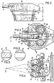
- FIGS. 1 to 3 show, within a tank tower 3 rotatably mounted in the vehicle trough 5, a loading machine for a tube weapon 13 combined from a magazine 1 and a feed device 16.
- the tube weapon 13 is arranged centrally in an external weapon shaft 36 of the armored tower 3 and is by a known tower-fixed cradle bearing 58 and a known height adjusting cylinder 59.
- the weapon shaft 36 prevents the tubular weapon 13 from influencing the outer turret height a because, when the returning tubular weapon 13 swivels within the angular range a pivotable about the shield pin 60 of the cradle bearing 58 by the leveling cylinder 59, the base piece 54 of the tubular weapon 13 from the Tower contour can emerge.
- a crew room 6 divided into two halves by the weapon shaft 36 is connected to one another for direct contact between the commander and the gunner via a communication tunnel 42 arranged below the weapon shaft 36.
- a tower bearing 61 known per se in the vehicle trough 5 centers the area b of the tank turret 3 accommodated by the vehicle trough 5 and at the same time supports the outer area a of the tank turret 3, the turret 3 being rotatable about the central axis 27 by a drive (not shown).
- the armored turret 3 is equipped with observation and aiming devices 55, entry and exit hatches 56, as well as an aperture machine gun 57 and a further machine gun, not shown, the functions of which are not relevant to the invention, however, and a detailed description is therefore unnecessary.
- Separate front panels 62 of the turret mouth area enable the arrangement of the aperture machine gun 57 and a mechanically coupled aid to the tube weapon 13 on both sides of the barrel weapon 13 while achieving all-round protection of the mounting of the shield journal 60 rifle scope 63 for the gunner.
- the tube weapon 13 which can be adjusted in height in the angular range (a + y) around the cradle bearing 58, assumes an index position 14 necessary for the loading process at an elevation angle ⁇ .
- the loading space 12 of the barrel weapon 13 is ready for receiving a new projectile 15 ready for insertion by a piecing device 64 arranged on the elongated barrel core axis 51 after the fall wedge lock 31 has been released.
- the piecing device 64 is attached to the armored turret 3 as a chain piecing device within the height range a via fastening elements, not shown.
- the projectile 15 rests in the loading position 14 on a charging cradle 8 of the feed device 16.
- the feed device 16 can be pivoted about a shaft 22 in the height region a of the armored turret 3, the shaft 22 being mounted horizontally in a bearing block 26 of a bearing 28 fastened to the turret 3.
- the bearing 28 consists essentially of two ring-shaped bearing halves, one bearing half being connected to a holder 29 connected to the armored turret 3 in the region of the tower bearing 61, reaching into the height region b and extending in the manner of a tube, and distributed next to one another on the circumference of the other bearing half the bearing blocks 26 of the feed devices 16 are firmly connected.
- the projectiles 15, which are suspended in the ammunition containers 25 designed as feed devices 16, can be rotated in a carousel-like manner about the central axis 27, as a result of which the magazine 1 designed in this way can assume a projectile removal position 10 independently of the rotary movement of the armored turret 3.
- the projectile 15 can be pivoted upwards from below by the ammunition container 25, which is also designed as a charging shell 8 and a feed device 16, by means of a drive 18 described in more detail in FIG. 4, into the position 14 ready for loading, which extends into the region 30 of the wedge lock 31 .
- the divided crew compartment 6 is secured to the outside of the magazine 1 by a bulkhead 37, which in particular protects the turret crew in the event of ammunition fire and ammunition deflagration.
- a bulkhead 37 which in particular protects the turret crew in the event of ammunition fire and ammunition deflagration.
- an articulated drive 40 of a sleeve clearer 39 which can be retracted and swiveled into the weapon shaft 36 is arranged.
- the sleeves 41 fall into the sleeve clearer 39, which is ready to receive near the bottom of the weapon shaft 36 and which, before each loading operation, is driven by the articulated drive 40 to eject the empty sleeve 41 into the rear area of the tank tower 3 is swung up.
- the case clearer 39 moves back into the starting position, the rear wall 44 of the case clearer 39 and a pivotable flap 45 closing a magazine hatch 46 through which, when the case clearer 39 and the flap 45 are pivoted away, the feed device 16 for loading a new projectile 15 into the Directions 24 is pivotable.
- Fig. 4 shows the drive 18 of the feed device 16, the piecing 64 and the drive 65 for the sleeve clearer 39 (Fig. 1).
- the drive 18, which can be pivoted about an axis 34 arranged in a vertical and tower-fixed manner, assumes a positive connection with a projection 32 of the shaft 22 projecting on one side, as a result of which the charging cradle 8 with the projectile 15 in the position 14 ready for loading (Fig. 1) can be swiveled up and swung back into the removal position 10.
- the profile of the extension 32 can be flat on both sides, a claw 33 of the drive 18, which can be pushed over it, according to FIG. 6 having a central, parallel slot.
- the drive 18 assumes a position pivoted out in the direction 35 from the positive connection with the attachment 32.
- the projectile 15 is transported into the loading space 12 (FIG. 1) by the piecing attachment 64 designed as a chain attachment.
- the chains of the chain applicator are taken up by the chain guides 66 in the retracted position.
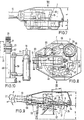
- FIGS. 7 to 9 A further embodiment variant of a loading machine equipped with an endless and vertically arranged magazine 2 and a feed device 17, which is arranged within a turret 4 of a tubular weapon 13 rotatably mounted in the vehicle trough 5, is illustrated in FIGS. 7 to 9.
- the barrel weapon 13 can be adjusted in height in the angular range (a + y) around the cradle bearing 58 by the leveling cylinder 59, the index position 14 required for the loading process, as already indicated in FIG. 1, being assimilable at an elevation angle ⁇ .
- the tower is designed in such a way that the barrel weapon 13 returning around area c does not touch the tower roof in an inclined position within the angular area a.
- the armored turret 4 also contains the observation and targeting devices 55 and 63 already marked in FIG. 3 and a hatch 56, with the only difference that these devices are all arranged on one side of the barrel weapon 13.
- the best of the commander and the gunner The existing tower crew is also seated on one side, but one behind the other in the crew room 7.
- a band magazine 2 is arranged inside the outer turret area a and the inner area b of the vehicle trough 5 and consists of two parallel circular tracks.
- the floors 15 standing vertically in the band magazine 2 are surrounded by a magazine cover.
- the magazine cover as a plastic housing with the bulkhead 48 compared to the crew room 7 offers increased protection against burning ammunition.
- the removal point 11 is arranged, from which the charging cradle 9 connected to the feed device 17 transports the projectiles 15 via an intermediate position 52 from below to the loading position 14 reaching into the area 30 of the wedge lock 31, only pivotably.
- the projectiles 15 are transported further within the band magazine 2 by a drive (not shown) and are pivoted out of the removal position 11 in the direction 53 and then in the direction 24 by the drives 20, 21 and 19 shown in FIG. 10.
- the automatic pivoting movement of the projectile 15, which is held in a charging cradle 9 connected to a pivoting lever 49 of the feed device 17, runs in the vertical direction 24 by rotating the pivoting lever 49 about a shaft 23 mounted horizontally in the height range a of the armored turret 4, either by a straight-line drive 20 connected to the pivot lever 49 or controlled in the direction 24 by a rotary drive 21 (FIG. 10) which can be connected to the shaft 23.
- the shaft 23 is mounted in a tower-fixed bearing block 67, which is advantageously arranged laterally next to the barrel weapon 13 to carry out the swiveling movements necessary for the loading process between the band magazine 2 and the wedge lock 31.
- the bearing block 67 can either accommodate a hydraulic piston-cylinder unit as a straight-line drive 20 or the drive 21 (FIG. 10) in a type of fastening (not shown).
- the projectile 15 In the loaded loading position 14, the projectile 15 can be transported into the loading space 12 (FIG. 1) by the tower-fixed attachment 64 already described.
- FIG. 10 shows the feed device 17 which can be pivoted about the shaft 23 with a charging cradle 9 which can be pivoted about the pivot lever 49 of the feed device 17, the projectile 15 being in two mutually perpendicular planes from the removal position 11 (FIG. 8) to the position ready for insertion 14 (Fig. 9) is pivotable.
- the pivot lever 49 can be pivoted vertically directly about the shaft 23 connected by the rotary drive 21 or by a rotary movement initiated by the drive 20 about the shaft 23.
- a drive 19 and a shaft 50 which can be driven by it are connected to the pivot lever 49, to which the charging cradle 9 is positively connected.
- the drives of the straightening system of barrel weapon 13 and armored turret 3, 4 and the drives of the automatic loader are preferably equipped with hydraulic drive units. which is particularly advantageous for small, space-saving components (cylinders, engines) with high performance. To avoid a possible fire hazard, a non-flammable liquid can be used as the transmission medium.
Landscapes
- Engineering & Computer Science (AREA)
- General Engineering & Computer Science (AREA)
- Aiming, Guidance, Guns With A Light Source, Armor, Camouflage, And Targets (AREA)
Claims (5)
Applications Claiming Priority (2)
| Application Number | Priority Date | Filing Date | Title |
|---|---|---|---|
| DE3320241 | 1983-06-03 | ||
| DE19833320241 DE3320241A1 (de) | 1983-06-03 | 1983-06-03 | Ladeautomat fuer ein panzerfahrzeug mit drehbarem panzerturm |
Publications (2)
| Publication Number | Publication Date |
|---|---|
| EP0141900A1 EP0141900A1 (fr) | 1985-05-22 |
| EP0141900B1 true EP0141900B1 (fr) | 1987-07-29 |
Family
ID=6200662
Family Applications (1)
| Application Number | Title | Priority Date | Filing Date |
|---|---|---|---|
| EP84105873A Expired EP0141900B1 (fr) | 1983-06-03 | 1984-05-23 | Dispositif de chargement automatique pour engin blindé avec tourelle rotative blindée |
Country Status (3)
| Country | Link |
|---|---|
| US (1) | US4632011A (fr) |
| EP (1) | EP0141900B1 (fr) |
| DE (2) | DE3320241A1 (fr) |
Families Citing this family (20)
| Publication number | Priority date | Publication date | Assignee | Title |
|---|---|---|---|---|
| DE3517056A1 (de) * | 1985-05-11 | 1986-11-13 | Rheinmetall GmbH, 4000 Düsseldorf | Vorrichtung zum ummunitionieren von patronierter munition aus einem wannen- in ein turmmagazin |
| US4700609A (en) * | 1985-10-04 | 1987-10-20 | Fmc Corporation | Autoloader for military vehicle |
| US4860633A (en) * | 1985-10-04 | 1989-08-29 | Fmc Corporation | Autoloader for military vehicle |
| US4823676A (en) * | 1985-10-04 | 1989-04-25 | Fmc Corporation | Autoloader for military vehicle |
| DE3604650A1 (de) * | 1986-02-14 | 1987-08-27 | Thyssen Industrie | Munitionsfoerdervorrichtung bei einem gepanzerten fahrzeug |
| DE3627042A1 (de) * | 1986-08-09 | 1988-02-11 | Kuka Wehrtechnik Gmbh | Vorrichtung zum laden von geschuetzen, insbesondere panzerhaubitzen |
| DE3722353A1 (de) * | 1987-07-07 | 1989-01-19 | Kuka Wehrtechnik Gmbh | Kampffahrzeug |
| DE3826652A1 (de) * | 1988-08-05 | 1990-02-08 | Rheinmetall Gmbh | Vorholsperrvorrichtung |
| SE462239B (sv) * | 1988-10-12 | 1990-05-21 | Bofors Ab | Anordning vid stridsvagn med oeverliggande kanon upphaengd i en klyka anordnad paa en vridbar del |
| DE3908346A1 (de) * | 1989-03-15 | 1990-09-20 | Wegmann & Co | Elevationslagerung fuer eine in einem panzerturm angeordnete grosskalibrige rohrwaffe |
| DE4115283C2 (de) * | 1991-05-10 | 1996-02-22 | Rheinmetall Ind Gmbh | Redundante Munitionsflußvorrichtung |
| US5223663A (en) * | 1991-12-23 | 1993-06-29 | General Electric Co. | Automated ammunition handling system |
| US20070006724A1 (en) * | 2005-05-20 | 2007-01-11 | Strong Russell W | A mobile gunner station |
| DE102007041294B4 (de) * | 2007-08-31 | 2009-12-17 | Rheinmetall Landsysteme Gmbh | Munitionsbevorratung |
| DE102007041292A1 (de) * | 2007-08-31 | 2009-03-05 | Rheinmetall Landsysteme Gmbh | Modularer, adaptierbarer ballistischer Schutzaufbau insbesondere für einen Waffenturm |
| US9618286B1 (en) | 2015-09-29 | 2017-04-11 | Christopher Andrew Plate | Ammunition magazine loader |
| US9689633B1 (en) | 2015-12-22 | 2017-06-27 | Christopher Andrew Plate | Magazine loader |
| US10598455B2 (en) | 2015-09-29 | 2020-03-24 | Plate Llc | Magazine ammunition loader |
| FR3052247B1 (fr) * | 2016-06-03 | 2019-08-02 | Nexter Systems | Tourelle canon comportant au moins un magasin a munition et caisse a munitions destinee a equiper un tel magasin |
| US12313368B2 (en) * | 2023-03-10 | 2025-05-27 | Meggitt Defense Systems, Inc. | Storage and loading system for large caliber ammunition |
Family Cites Families (11)
| Publication number | Priority date | Publication date | Assignee | Title |
|---|---|---|---|---|
| US2433568A (en) * | 1942-12-28 | 1947-12-30 | Julius Kayser & Co | Full-fashioned knitting machine |
| US2499271A (en) * | 1944-02-07 | 1950-02-28 | Molins Machine Co Ltd | Ammunition feeding device for ordnance |
| US2837303A (en) * | 1956-02-02 | 1958-06-03 | Vall Guy B De | Landing gear for seaplanes |
| US2826136A (en) * | 1956-03-28 | 1958-03-11 | Lester L Smith | Roof type ventilator |
| US3046642A (en) * | 1960-06-15 | 1962-07-31 | White | Automatic key chain assembly apparatus |
| DE1578093A1 (de) * | 1967-12-15 | 1971-05-13 | Bundesrep Deutschland | Munitionsmagazin mit Kippaufzug-Ladeeinrichtung,insbesondere fuer die Hauptwaffe von Kampfpanzern |
| GB1523432A (en) * | 1971-10-29 | 1978-08-31 | Marconi Co Ltd | Turret gun arrangements |
| DE2433568A1 (de) * | 1974-07-12 | 1976-01-29 | Krauss Maffei Ag | Ladevorrichtung fuer die geschosse einer kanone in kampffahrzeugen |
| DE2826136C3 (de) * | 1978-06-15 | 1982-03-04 | Thyssen Industrie Ag, 4300 Essen | Vorrichtung für den Munitionstransport aus einem gepanzerten Fahrzeug zu einem auf einer Plattform fest angeordneten scheitellafettierten Geschütz |
| DE2837303C2 (de) * | 1978-08-26 | 1983-12-15 | Thyssen Industrie Ag, 4300 Essen | Vorrichtung für Munitionslagerung und -transport bei einem Panzerfahrzeug mit einem scheitellafettierten Geschütz |
| DE3046642A1 (de) * | 1980-12-11 | 1982-07-08 | Wegmann & Co, 3500 Kassel | Automatische ladeeinrichtung fuer schusswaffen |
-
1983
- 1983-06-03 DE DE19833320241 patent/DE3320241A1/de not_active Withdrawn
-
1984
- 1984-05-23 DE DE8484105873T patent/DE3465144D1/de not_active Expired
- 1984-05-23 EP EP84105873A patent/EP0141900B1/fr not_active Expired
- 1984-06-05 US US06/617,677 patent/US4632011A/en not_active Expired - Lifetime
Also Published As
| Publication number | Publication date |
|---|---|
| US4632011A (en) | 1986-12-30 |
| EP0141900A1 (fr) | 1985-05-22 |
| DE3465144D1 (en) | 1987-09-03 |
| DE3320241A1 (de) | 1984-12-06 |
Similar Documents
| Publication | Publication Date | Title |
|---|---|---|
| EP0141900A1 (fr) | Dispositif de chargement automatique pour engin blindé avec tourelle rotative blindée | |
| EP0178484B1 (fr) | Chargeur pour canons | |
| EP0331980B1 (fr) | Véhicule de combat, en particulier canon blindé | |
| EP1887306B1 (fr) | Installation d'arme | |
| DE3332225C2 (fr) | ||
| DE10258263B4 (de) | Schießmodul | |
| DE3041866C2 (de) | Vorrichtung zum Transport von Munition aus einem Munitionsbehälter zum Verschluß einer Waffe | |
| EP0277478B1 (fr) | Char de combat | |
| DE3642920A1 (de) | Kampffahrzeug, insbesondere panzerhaubitze | |
| EP0042166B1 (fr) | Char comportant un système d'échange de container à munitions | |
| EP0301259A1 (fr) | Véhicule de combat | |
| DE69206698T2 (de) | Automatische Munitionszuführvorrichtung für Panzerkanonen | |
| DE3701713C2 (fr) | ||
| DE3016928A1 (de) | Vorrichtung zum transport von munition aus einem munitionsbehaelter zur abschussvorrichtung | |
| EP2587208B1 (fr) | Véhicule militaire, récipient de transport et procédé de rangement d'objets d'équipement | |
| EP1557634A1 (fr) | Dispositif pour le support d'une plate-forme d'armes | |
| DE1578069C3 (de) | Zubringvorrichtung in Form einer im Inneren eines gepanzerten Fahrzeuges drehbar angeordneten Magazintrommel für eine Abschußvorrichtung für Flugkörper mit Rückstoßantrieb | |
| EP0428825B1 (fr) | Chargeur pour mortier à chargement par la bouche | |
| DE4115283C2 (de) | Redundante Munitionsflußvorrichtung | |
| DE3701712C2 (fr) | ||
| EP0221935A1 (fr) | Dispositif de transfert de cartouches de munition d'un chargeur de bati a un chargeur de tourelle. | |
| EP0635695B1 (fr) | Véhicule de combat, en particulier obusier, comportant des magasins de munitions | |
| DE2413983A1 (de) | Automatische ladeeinrichtung fuer eine kanone, insbesondere fuer die waffe eines kampfpanzers | |
| DE10160207B4 (de) | Munitionsmagazin | |
| EP1273869B1 (fr) | Véhicule blindé |
Legal Events
| Date | Code | Title | Description |
|---|---|---|---|
| PUAI | Public reference made under article 153(3) epc to a published international application that has entered the european phase |
Free format text: ORIGINAL CODE: 0009012 |
|
| 17P | Request for examination filed |
Effective date: 19850223 |
|
| AK | Designated contracting states |
Designated state(s): DE FR GB IT SE |
|
| 17Q | First examination report despatched |
Effective date: 19860115 |
|
| ITF | It: translation for a ep patent filed | ||
| GRAA | (expected) grant |
Free format text: ORIGINAL CODE: 0009210 |
|
| AK | Designated contracting states |
Kind code of ref document: B1 Designated state(s): DE FR GB IT SE |
|
| REF | Corresponds to: |
Ref document number: 3465144 Country of ref document: DE Date of ref document: 19870903 |
|
| ET | Fr: translation filed | ||
| PLBE | No opposition filed within time limit |
Free format text: ORIGINAL CODE: 0009261 |
|
| STAA | Information on the status of an ep patent application or granted ep patent |
Free format text: STATUS: NO OPPOSITION FILED WITHIN TIME LIMIT |
|
| 26N | No opposition filed | ||
| PGFP | Annual fee paid to national office [announced via postgrant information from national office to epo] |
Ref country code: SE Payment date: 19890411 Year of fee payment: 6 |
|
| PGFP | Annual fee paid to national office [announced via postgrant information from national office to epo] |
Ref country code: FR Payment date: 19890428 Year of fee payment: 6 |
|
| ITTA | It: last paid annual fee | ||
| PGFP | Annual fee paid to national office [announced via postgrant information from national office to epo] |
Ref country code: GB Payment date: 19890531 Year of fee payment: 6 |
|
| PG25 | Lapsed in a contracting state [announced via postgrant information from national office to epo] |
Ref country code: GB Effective date: 19900523 |
|
| PG25 | Lapsed in a contracting state [announced via postgrant information from national office to epo] |
Ref country code: SE Effective date: 19900524 |
|
| GBPC | Gb: european patent ceased through non-payment of renewal fee | ||
| PG25 | Lapsed in a contracting state [announced via postgrant information from national office to epo] |
Ref country code: FR Effective date: 19910131 |
|
| REG | Reference to a national code |
Ref country code: FR Ref legal event code: ST |
|
| EUG | Se: european patent has lapsed |
Ref document number: 84105873.8 Effective date: 19910115 |
|
| PGFP | Annual fee paid to national office [announced via postgrant information from national office to epo] |
Ref country code: DE Payment date: 20000422 Year of fee payment: 17 |
|
| PG25 | Lapsed in a contracting state [announced via postgrant information from national office to epo] |
Ref country code: DE Free format text: LAPSE BECAUSE OF NON-PAYMENT OF DUE FEES Effective date: 20020301 |