EP0141929B1 - Méthode et dispositif de mesure de modifications de l'état capacitif d'une clôture protectrice - Google Patents
Méthode et dispositif de mesure de modifications de l'état capacitif d'une clôture protectrice Download PDFInfo
- Publication number
- EP0141929B1 EP0141929B1 EP84109632A EP84109632A EP0141929B1 EP 0141929 B1 EP0141929 B1 EP 0141929B1 EP 84109632 A EP84109632 A EP 84109632A EP 84109632 A EP84109632 A EP 84109632A EP 0141929 B1 EP0141929 B1 EP 0141929B1
- Authority
- EP
- European Patent Office
- Prior art keywords
- electrodes
- electrode
- measured values
- individual
- mean value
- Prior art date
- Legal status (The legal status is an assumption and is not a legal conclusion. Google has not performed a legal analysis and makes no representation as to the accuracy of the status listed.)
- Expired
Links
Images
Classifications
-
- G—PHYSICS
- G08—SIGNALLING
- G08B—SIGNALLING SYSTEMS, e.g. PERSONAL CALLING SYSTEMS; ORDER TELEGRAPHS; ALARM SYSTEMS
- G08B13/00—Burglar, theft or intruder alarms
- G08B13/22—Electrical actuation
- G08B13/26—Electrical actuation by proximity of an intruder causing variation in capacitance or inductance of a circuit
Definitions
- the invention relates to a method and an arrangement for measuring capacitive changes in state of a protective fence having a plurality of wire electrodes arranged in parallel, wherein an alternating voltage is applied to at least one of the electrodes and measurement signals are received at at least one electrode, and interference from temporal changes in the measurement signals - or alarm criteria are derived.
- Capacitive protective fences are used in particular for monitoring extensive open-air systems, since they can be used to reliably detect all changes in condition and thus the approach and intrusion of unauthorized persons even in confusing terrain.
- changes in capacity are also caused by interference, in particular by weather conditions, such as rain, snow and frost, but also by birds and small animals, which temporarily sit on the electrodes or slip under the fence. Such interferences should on the one hand not lead to the alarm being given, while on the other hand an intruding person must be reliably recognized and reported in any case.
- the object of the invention is to provide a measuring method and an arrangement for measuring capacitive changes in state of the type mentioned at the outset, the circuit complexity for the measurement being considerably reduced compared to the known methods and nevertheless high immunity to interference being ensured.
- this object is achieved in that the current intensity is determined as a measurement signal in each of the connected electrodes and a measurement value for the operating capacity of the electrode in question is obtained therefrom and that from the change in the measurement values of individual electrodes in comparison with their respective rest value and / or in In comparison with the other electrodes, fault or alarm signals can be derived.
- each measured current value is proportional to the operating capacity of this electrode in question with a particular connection in the entire electrode system. It is not necessary to determine the individual partial capacities and own partial capacities.
- the measured values corresponding to the number of electrodes can be evaluated via the known properties assigned to the respective electrode. For example, electrode thickening that occurs simultaneously on all electrodes can be identified as an accumulation of water, snow or frost and can be compensated for in the evaluation.
- time-current profiles or time operating capacity profiles that differ significantly from the profile of faults.
- a human's penetration between two electrodes can be distinguished from a bird's placement by comparing the steepness of the current change with given patterns.
- the fact can be used that the current changes of neighboring electrodes are determined by the mass of the approaching body, so that here too the comparison with predefined patterns enables a distinction.
- An arrangement for carrying out the method according to the invention is expediently constructed in such a way that a transmitter device can be connected to one or more electrodes, that current measuring devices for measuring the current intensity are provided in each of the electrodes, and that the current measuring devices have an evaluation circuit with comparison devices for comparing the individual measured values with the Measured values of the other electrodes determined at the same time, followed by the measured values of the same electrode determined at an earlier point in time and with stored values.
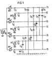
- Fig. 1 shows schematically a protective fence with seven electrodes, which are alternately connected in the order of their arrangement one above the other as transmitting electrodes and as receiving electrodes.
- the transmitting electrodes 1 S, 3S, 5S and 7S are all connected to a common alternating current transmitter S which generates an alternating voltage U s of, for example, 100 V and 10 kHz.
- the receiving electrodes 2E, 4E and 6E are all connected to ground potential.
- Each electrode has an intrinsic part capacitance with respect to the ground potential, for example electrode 1S has capacitance C, 1 or electrode 7S has intrinsic part capacitance C 77 .
- There are partial capacitances between the individual electrodes for example capacitance C 12 between electrodes 1S and 2E or capacitance C52 between electrodes 5S and 2E.
- One of the current measuring devices IM1 to IM7 is switched on in the circuit of each electrode 1 S to 7S, the current I 1 S, 1 2E ... to 1 7s flowing in the respective transmitting or receiving electrode being present when the transmission voltage U s is applied the transmitter electrodes is measured.
- the current measured in the respective electrode is proportional to the operating capacity of this relevant electrode. For the example shown in FIG. 1, the following applies to the individual currents with the same transmission voltage U s :
- the sum of the respective partial capacities and own partial capacities in parentheses is the operating capacity for the electrode in question.
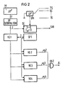
- FIG. 2 shows in a block diagram the evaluation of the measurement signals obtained according to FIG. 1.
- the current measuring device IM which contains, for example, the seven current measuring devices IM1 to IM7 from FIG. 1, the seven current measured values are passed over a bandpass filter BF for further evaluation in order to switch off higher-frequency processes.
- the bandpass filter covers a range from 0.0001 Hz to about 10 Hz.
- the current measuring device IM can of course also contain a single measuring device instead of the individual measuring devices IM1 to IM7, with which the seven electrodes are scanned using multiplex technology. With each scan, the new measured values are compared in a comparison device VG1 with the earlier measured values of the same electrodes contained in a memory SP1. If the values are unchanged from the previous values or rest values, there is no need for further processing. However, the measured values are stored for a certain time, so that a certain number of comparison measured values from previous samples are available.
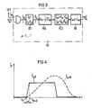
- the mode of operation of the comparison device VG2 can be seen from FIG. 3.
- the measured values of the operating capacitances C are transmitted to a first arithmetic circuit RE1 via an AND gate AN1.
- an associated wire diameter D ⁇ is calculated for each operating capacity.
- the wire diameter is a function f ⁇ of the operating capacity C ⁇ . This function is different for each wire. Therefore, when the system is set up, these functions f ⁇ (C ⁇ ) are determined experimentally for each electrode and stored in the computing circuit RE1. As long as the electrodes are unchanged, the actual electrode diameter D results in the computing circuit RE1.
- This electrode diameter can increase due to weather influences, for example due to the formation of frost, which results in a corresponding change in the measured operating capacity.
- the operating capacity can also change due to other influences, such as the placement of a bird or the penetration of a human being, in such a way that an apparently enlarged electrode diameter is calculated in the computing circuit RE1.
- This mean value D M is then fed to a second arithmetic circuit RE2.
- the function g ⁇ is the inverse function to the function f " described above for each individual electrode and, like this, denotes the dependence between the electrode diameter and the operating capacity for the normal state of the individual electrodes.
- the value C ' ⁇ g ⁇ (D M ) is now formed for each electrode from the average electrode diameter D M via the function g " and subtracted from the measured value for the operating capacity C ⁇ .
- the difference, ie the compensated value C " differs for some Electrodes significantly from 0 or a threshold value CS ⁇ k , an intruder can be identified therefrom.
- the values C "k are fed to a comparator device KO, in which a threshold value C S ⁇ . Is stored for each electrode. If the comparator device shows that a value C ⁇ k is greater than the associated threshold value S S ⁇ , then Output a signal vg2 emitted.
- the measured values C "of the individual electrodes are fed to further comparison devices VG3 and VG4.
- the slope of the change in the measured value is determined by comparison with the stored measured values of the preceding scans from the memory SP1 and compared with a predetermined pattern. This evaluates the fact that, for example, a bird approaches the fence much faster than a human can.
- the curve C ⁇ v represents the The course of the measured value when approaching a bird. Between the two measuring times T m and T m + 1 , a steep increase in the operating capacity C ⁇ is determined. The operating capacity then remains the same until a steep drop in operating capacity indicates that the bird is flying away at a later point in time.
- the curve for the approach of a person crawling under the fence shows a completely different course.
- the curve C ⁇ M shows a relatively slow rise between the times T m and Tm + and, accordingly, a slower fall again at a later point in time.
- VG3 (Fig. 2) is therefore, that of the approach speed of the intruder, from the time course of the change of C. , derived a signal in comparison with a threshold value v s . From the condition the alarm criterion vg3 is derived here.
- the changes in the measured values determined in comparison with the previous scans are compared with stored sample values. These sample values set a limit for the alarm signaling where the mass and the change in the measured value caused by this mass can be assigned to the pattern of a small animal or a bird in comparison to the pattern caused by the mass of a human body. This is done in a simple manner by comparing the absolute measured value change ⁇ C ⁇ corresponding to the mass of the intruder with a threshold value cs.
- the threshold value for the receiving electrodes and for the transmitting electrodes can be different. This threshold value or these threshold values are likewise determined experimentally for the system in question and stored in the comparison device VG4. With each query, the relationship can the alarm criterion vg4 is derived if the change in operating capacity due to the mass of the penetrating body is above the threshold value.
- An alarm signal AL is triggered via the coincidence element AN2 only when the determined changes in measured values cannot be fully compensated for either by the mean value compensation in the comparison device VG2 or by the steepness-related compensation in the comparison device VG3 or in the delimitation compensation of the comparison device VG4.
- a sabotage detection SE is also provided in a manner known per se, as shown in FIG. 2.
- This sabotage detection device SE is supplied with both the measured current values from the current measuring device IM for the individual electrodes and the measured voltage value at the individual electrodes.
- a measuring device UM is used for voltage measurement, which can be connected via a sampling switch AS to the individual electrodes 1S to 7S with each query. If it is found in the sabotage detection device SE that the voltage drops sharply or goes towards 0 or that the electrode current 1 at one of the electrodes goes towards 0, then a short circuit or a wire break is recognized and evaluated to generate a sabotage signal SAB.
- the described evaluation of the measured values is expediently carried out by a microcomputer in which the respective measured values and the values required for comparison are stored and which carries out the comparison operations.
Landscapes
- Physics & Mathematics (AREA)
- General Physics & Mathematics (AREA)
- Burglar Alarm Systems (AREA)
- Measurement Of Radiation (AREA)
- Investigating Or Analyzing Materials By The Use Of Ultrasonic Waves (AREA)
- Measurement Of Length, Angles, Or The Like Using Electric Or Magnetic Means (AREA)
- Investigating Or Analyzing Materials By The Use Of Electric Means (AREA)
- Measurement Of Resistance Or Impedance (AREA)
- Emergency Alarm Devices (AREA)
Claims (12)
Priority Applications (1)
| Application Number | Priority Date | Filing Date | Title |
|---|---|---|---|
| AT84109632T ATE31122T1 (de) | 1983-08-16 | 1984-08-13 | Verfahren und anordnung zur messung von kapazitiven zustandsaenderungen an einem schutzzaun. |
Applications Claiming Priority (2)
| Application Number | Priority Date | Filing Date | Title |
|---|---|---|---|
| DE3329554 | 1983-08-16 | ||
| DE19833329554 DE3329554A1 (de) | 1983-08-16 | 1983-08-16 | Verfahren und anordnung zur messung von kapazitiven zustandsaenderungen an einem schutzzaun |
Publications (2)
| Publication Number | Publication Date |
|---|---|
| EP0141929A1 EP0141929A1 (fr) | 1985-05-22 |
| EP0141929B1 true EP0141929B1 (fr) | 1987-11-25 |
Family
ID=6206667
Family Applications (1)
| Application Number | Title | Priority Date | Filing Date |
|---|---|---|---|
| EP84109632A Expired EP0141929B1 (fr) | 1983-08-16 | 1984-08-13 | Méthode et dispositif de mesure de modifications de l'état capacitif d'une clôture protectrice |
Country Status (7)
| Country | Link |
|---|---|
| US (1) | US4684932A (fr) |
| EP (1) | EP0141929B1 (fr) |
| AT (1) | ATE31122T1 (fr) |
| DE (2) | DE3329554A1 (fr) |
| ES (1) | ES8505123A1 (fr) |
| GR (1) | GR80118B (fr) |
| MX (1) | MX156464A (fr) |
Families Citing this family (15)
| Publication number | Priority date | Publication date | Assignee | Title |
|---|---|---|---|---|
| EP0239807B1 (fr) * | 1986-03-04 | 1991-04-17 | Siemens Aktiengesellschaft | Système capacitif de protection contre l'intrusion |
| EP0256482A1 (fr) * | 1986-08-13 | 1988-02-24 | Siemens Aktiengesellschaft | Clôture capacitive de sécurité |
| EP0256484A1 (fr) * | 1986-08-13 | 1988-02-24 | Siemens Aktiengesellschaft | Clôture capacitive de sécurité |
| DE3814063C2 (de) * | 1988-04-26 | 1994-01-27 | Siemens Ag | Isolatoranordnung an einem kapazitiven Intrusions-Schutzzaun |
| DE3814062C2 (de) * | 1988-04-26 | 1994-01-27 | Siemens Ag | Isolatoranordnung an einem kapazitiven Intrusions-Schutzzaun |
| GB2229303B (en) * | 1989-03-14 | 1993-02-10 | Shorrock Ltd | Alarm signal processing means |
| DE58905396D1 (de) * | 1989-04-11 | 1993-09-30 | Siemens Ag | Verfahren zur Kompensation störender Signalanteile in den Messsignalen eines Messsystems. |
| US5150099A (en) * | 1990-07-19 | 1992-09-22 | Lienau Richard M | Home security system and methodology for implementing the same |
| US5225808A (en) * | 1990-08-08 | 1993-07-06 | Olivadotti William C | Long range intruder sensor |
| US5525969A (en) * | 1992-05-18 | 1996-06-11 | Ladue; Christoph K. | Monitoring device for location verification |
| US5603287A (en) * | 1993-04-12 | 1997-02-18 | Houck; George B. | Animal sensing and repelling system |
| DE19817640A1 (de) * | 1998-04-21 | 1999-11-04 | Gerhard Von Der Emde | Unterwasserdetektor für kapazitive Objekteigenschaften |
| US7450006B1 (en) | 2006-04-06 | 2008-11-11 | Doyle Alan T | Distributed perimeter security threat confirmation |
| US7688202B1 (en) | 2006-04-06 | 2010-03-30 | Kelly Research Corp. | Distributed perimeter security threat determination |
| US20120169499A1 (en) * | 2010-12-31 | 2012-07-05 | Schneider Electric Buildings Ab | Method and system for monitoring physical security via detecting potential intrusion |
Family Cites Families (12)
| Publication number | Priority date | Publication date | Assignee | Title |
|---|---|---|---|---|
| US2971184A (en) * | 1957-05-14 | 1961-02-07 | American District Telegraph Co | Intruder alarm system |
| US3103003A (en) * | 1959-06-02 | 1963-09-03 | Diebold Inc | Capacity alarm system |
| GB892872A (en) * | 1960-09-12 | 1962-04-04 | American District Telegraph Co | Intruder alarm systems |
| US3047849A (en) * | 1960-11-21 | 1962-07-31 | Mosler Res Products Inc | Electronic intrusion protection array system |
| DE1220289B (de) * | 1961-02-10 | 1966-06-30 | Siemens Ag | Empfangsschaltung fuer auf rasche Zustandsaenderungen, vorzugsweise Kapazitaets-aenderungen, ansprechende Alarmeinrichtungen |
| SU479056A1 (ru) * | 1972-04-28 | 1975-07-30 | Предприятие П/Я Г-4783 | Система дл автоматизированного контрол параметров конденсаторов |
| US3778807A (en) * | 1972-12-13 | 1973-12-11 | Eg & G Inc | Capacitive intrusion detection system with balanced resonant circuits |
| DE2539501B2 (de) * | 1975-09-05 | 1979-04-26 | Rode, Johannes, 2000 Hamburg | Anlage zur Überwachung von Objekten in Form von Gegenständen oder Räumen |
| US4389646A (en) * | 1980-04-30 | 1983-06-21 | Fuji Electric Co. Ltd. | Displacement converting circuit arrangement |
| DE3110352A1 (de) * | 1981-03-17 | 1982-11-18 | Siemens AG, 1000 Berlin und 8000 München | Verfahren und vorrichtung zum messen der teil- und/oder eigenteilkapazitaeten an einem kapazitiven schutzzaun |
| DE3110310A1 (de) * | 1981-03-17 | 1982-09-30 | Siemens AG, 1000 Berlin und 8000 München | Elektrodenanordnung an einem kapazitiven schutzzaun |
| DE3222640C2 (de) * | 1982-06-16 | 1984-03-29 | Siemens AG, 1000 Berlin und 8000 München | Meßanordnung für eine Mehrzahl von Elektroden aufweisende, kapazitive Schutzzäune |
-
1983
- 1983-08-16 DE DE19833329554 patent/DE3329554A1/de not_active Withdrawn
-
1984
- 1984-08-08 US US06/638,765 patent/US4684932A/en not_active Expired - Fee Related
- 1984-08-13 AT AT84109632T patent/ATE31122T1/de not_active IP Right Cessation
- 1984-08-13 DE DE8484109632T patent/DE3467824D1/de not_active Expired
- 1984-08-13 EP EP84109632A patent/EP0141929B1/fr not_active Expired
- 1984-08-14 GR GR80118A patent/GR80118B/el unknown
- 1984-08-14 ES ES535162A patent/ES8505123A1/es not_active Expired
- 1984-08-15 MX MX202394A patent/MX156464A/es unknown
Also Published As
| Publication number | Publication date |
|---|---|
| DE3329554A1 (de) | 1985-03-07 |
| MX156464A (es) | 1988-08-24 |
| EP0141929A1 (fr) | 1985-05-22 |
| ES535162A0 (es) | 1985-05-01 |
| ATE31122T1 (de) | 1987-12-15 |
| ES8505123A1 (es) | 1985-05-01 |
| DE3467824D1 (en) | 1988-01-07 |
| US4684932A (en) | 1987-08-04 |
| GR80118B (en) | 1984-12-14 |
Similar Documents
| Publication | Publication Date | Title |
|---|---|---|
| EP0141929B1 (fr) | Méthode et dispositif de mesure de modifications de l'état capacitif d'une clôture protectrice | |
| DE3611816C2 (fr) | ||
| DE102013001066B4 (de) | Kapazitiver Näherungssensor | |
| DE202007016734U1 (de) | Einklemmsensor | |
| EP0042501B1 (fr) | Dispositif pour la transmission des valeurs mesurées dans un système d'avertissement d'incendie | |
| DE3211550C2 (de) | Gleichstrommeldeanlage | |
| DE2427328C2 (de) | Einbruchsalarmanlage | |
| DE112019000888T5 (de) | System zur Erdung und Diagnose | |
| EP0060319B1 (fr) | Procédé et dispositif de mesure des capacités d'une cloture de protection à effet capacitif | |
| EP1197936A2 (fr) | Système d'alarme | |
| DE102015204375B3 (de) | Anordnung und Verfahren zur kapazitiven Sitzbelegungserkennung für Fahrzeugsitze | |
| EP3994473B1 (fr) | Évaluation de signaux d'évacuation de pièces | |
| DE2453439A1 (de) | Kapazitiver fuehler fuer automatische tueren | |
| DE2529034C3 (de) | Einrichtung zur kapazitiven Überwachung von Flächen gegen mechanische Durchdringung | |
| DE102017129068B4 (de) | Verteiltes Sensorsystem zur Erfassung von Körperteilen und Personen in den Gefahrenbereichen eines Cabrioverdecks | |
| DE69309694T2 (de) | Nachweis von störungen in starkstromleitungen | |
| EP0288952B1 (fr) | Procédé et dispositif de mesure de la vitesse de véhicules | |
| EP0927356B2 (fr) | Procede de verification de composants electriques et dispositif permettant de mettre ledit procede en oeuvre | |
| DE2416738A1 (de) | Fuehlerelement und schaltung fuer ein fuehlerelement | |
| DE102024204230B3 (de) | Vorrichtung und Verfahren zur Erfassung und Überwachung einer analogen Messgröße | |
| DE102022003602A1 (de) | Verfahren zum Erkennen einer Anwesenheit einer menschlichen Hand in einem Greifbereich eines Lenkrads | |
| EP0239807A1 (fr) | Système capacitif de protection contre l'intrusion | |
| DE102010063416B4 (de) | Vorrichtung zur Datenübertragung, Verwendung der Vorrichtung und Verfahren zum Justieren der Vorrichtung | |
| DE10160213A1 (de) | Messeinrichtung für elektrochemische Messgrössen, insbesondere pH-Messeinrichtung | |
| DE10018051B4 (de) | Näherungssensor |
Legal Events
| Date | Code | Title | Description |
|---|---|---|---|
| PUAI | Public reference made under article 153(3) epc to a published international application that has entered the european phase |
Free format text: ORIGINAL CODE: 0009012 |
|
| AK | Designated contracting states |
Designated state(s): AT DE FR GB IT NL |
|
| 17P | Request for examination filed |
Effective date: 19850627 |
|
| 17Q | First examination report despatched |
Effective date: 19861105 |
|
| GRAA | (expected) grant |
Free format text: ORIGINAL CODE: 0009210 |
|
| AK | Designated contracting states |
Kind code of ref document: B1 Designated state(s): AT DE FR GB IT NL |
|
| REF | Corresponds to: |
Ref document number: 31122 Country of ref document: AT Date of ref document: 19871215 Kind code of ref document: T |
|
| REF | Corresponds to: |
Ref document number: 3467824 Country of ref document: DE Date of ref document: 19880107 |
|
| ITF | It: translation for a ep patent filed | ||
| ET | Fr: translation filed | ||
| GBT | Gb: translation of ep patent filed (gb section 77(6)(a)/1977) | ||
| PLBI | Opposition filed |
Free format text: ORIGINAL CODE: 0009260 |
|
| 26 | Opposition filed |
Opponent name: TELENORMA TELEFONBAU UND NORMALZEIT GMBH Effective date: 19880420 |
|
| NLR1 | Nl: opposition has been filed with the epo |
Opponent name: TELENORMA TELEFONBAU UND NORMALZEIT GMBH |
|
| PLAB | Opposition data, opponent's data or that of the opponent's representative modified |
Free format text: ORIGINAL CODE: 0009299OPPO |
|
| R26 | Opposition filed (corrected) |
Opponent name: TELENORMA GMBH Effective date: 19880420 |
|
| NLXE | Nl: other communications concerning ep-patents (part 3 heading xe) |
Free format text: IN PAT.BUL.16/88:CORR.:TELENORMA GMBH |
|
| ITTA | It: last paid annual fee | ||
| PGFP | Annual fee paid to national office [announced via postgrant information from national office to epo] |
Ref country code: GB Payment date: 19930714 Year of fee payment: 10 |
|
| PGFP | Annual fee paid to national office [announced via postgrant information from national office to epo] |
Ref country code: AT Payment date: 19930716 Year of fee payment: 10 |
|
| PGFP | Annual fee paid to national office [announced via postgrant information from national office to epo] |
Ref country code: FR Payment date: 19930819 Year of fee payment: 10 |
|
| PGFP | Annual fee paid to national office [announced via postgrant information from national office to epo] |
Ref country code: NL Payment date: 19930831 Year of fee payment: 10 |
|
| PGFP | Annual fee paid to national office [announced via postgrant information from national office to epo] |
Ref country code: DE Payment date: 19931020 Year of fee payment: 10 |
|
| PG25 | Lapsed in a contracting state [announced via postgrant information from national office to epo] |
Ref country code: GB Effective date: 19940813 Ref country code: AT Effective date: 19940813 |
|
| PG25 | Lapsed in a contracting state [announced via postgrant information from national office to epo] |
Ref country code: NL Effective date: 19950301 |
|
| GBPC | Gb: european patent ceased through non-payment of renewal fee |
Effective date: 19940813 |
|
| NLV4 | Nl: lapsed or anulled due to non-payment of the annual fee | ||
| PG25 | Lapsed in a contracting state [announced via postgrant information from national office to epo] |
Ref country code: FR Effective date: 19950428 |
|
| PG25 | Lapsed in a contracting state [announced via postgrant information from national office to epo] |
Ref country code: DE Effective date: 19950503 |
|
| REG | Reference to a national code |
Ref country code: FR Ref legal event code: ST |
|
| PLBN | Opposition rejected |
Free format text: ORIGINAL CODE: 0009273 |
|
| STAA | Information on the status of an ep patent application or granted ep patent |
Free format text: STATUS: OPPOSITION REJECTED |
|
| 27O | Opposition rejected |
Effective date: 19950824 |