EP0142123A2 - Procédé et dispositif pour la dénitrification biologique de l'eau - Google Patents
Procédé et dispositif pour la dénitrification biologique de l'eau Download PDFInfo
- Publication number
- EP0142123A2 EP0142123A2 EP84113385A EP84113385A EP0142123A2 EP 0142123 A2 EP0142123 A2 EP 0142123A2 EP 84113385 A EP84113385 A EP 84113385A EP 84113385 A EP84113385 A EP 84113385A EP 0142123 A2 EP0142123 A2 EP 0142123A2
- Authority
- EP
- European Patent Office
- Prior art keywords
- reactor
- carrier material
- water
- gas
- reducing gas
- Prior art date
- Legal status (The legal status is an assumption and is not a legal conclusion. Google has not performed a legal analysis and makes no representation as to the accuracy of the status listed.)
- Granted
Links
Images
Classifications
-
- C—CHEMISTRY; METALLURGY
- C02—TREATMENT OF WATER, WASTE WATER, SEWAGE, OR SLUDGE
- C02F—TREATMENT OF WATER, WASTE WATER, SEWAGE, OR SLUDGE
- C02F3/00—Biological treatment of water, waste water, or sewage
- C02F3/30—Aerobic and anaerobic processes
- C02F3/302—Nitrification and denitrification treatment
-
- C—CHEMISTRY; METALLURGY
- C02—TREATMENT OF WATER, WASTE WATER, SEWAGE, OR SLUDGE
- C02F—TREATMENT OF WATER, WASTE WATER, SEWAGE, OR SLUDGE
- C02F3/00—Biological treatment of water, waste water, or sewage
- C02F3/02—Aerobic processes
- C02F3/10—Packings; Fillings; Grids
-
- C—CHEMISTRY; METALLURGY
- C02—TREATMENT OF WATER, WASTE WATER, SEWAGE, OR SLUDGE
- C02F—TREATMENT OF WATER, WASTE WATER, SEWAGE, OR SLUDGE
- C02F3/00—Biological treatment of water, waste water, or sewage
- C02F3/28—Anaerobic digestion processes
- C02F3/2806—Anaerobic processes using solid supports for microorganisms
-
- C—CHEMISTRY; METALLURGY
- C02—TREATMENT OF WATER, WASTE WATER, SEWAGE, OR SLUDGE
- C02F—TREATMENT OF WATER, WASTE WATER, SEWAGE, OR SLUDGE
- C02F3/00—Biological treatment of water, waste water, or sewage
- C02F3/30—Aerobic and anaerobic processes
- C02F3/301—Aerobic and anaerobic treatment in the same reactor
-
- Y—GENERAL TAGGING OF NEW TECHNOLOGICAL DEVELOPMENTS; GENERAL TAGGING OF CROSS-SECTIONAL TECHNOLOGIES SPANNING OVER SEVERAL SECTIONS OF THE IPC; TECHNICAL SUBJECTS COVERED BY FORMER USPC CROSS-REFERENCE ART COLLECTIONS [XRACs] AND DIGESTS
- Y02—TECHNOLOGIES OR APPLICATIONS FOR MITIGATION OR ADAPTATION AGAINST CLIMATE CHANGE
- Y02W—CLIMATE CHANGE MITIGATION TECHNOLOGIES RELATED TO WASTEWATER TREATMENT OR WASTE MANAGEMENT
- Y02W10/00—Technologies for wastewater treatment
- Y02W10/10—Biological treatment of water, waste water, or sewage
Definitions
- the invention relates to a process for the biological denitrification of water, in which the water to be denitrified is treated using a gaseous reducing agent in a reactor operated under anoxic conditions and containing a carrier material for the denitrifiers, and to an apparatus for carrying out the process.
- Nitrogen contained in wastewater is known to be eliminated in biological sewage plants by nitrification and denitrification.
- nitrification which mainly takes place only after extensive oxidation of the carbon compounds and requires low sludge loads, sufficient oxygen supply and high sludge age, autotrophic bacteria convert ammonium nitrogen to nitrate and nitrite.
- Denitrification reduces nitrate and nitrite to elemental nitrogen under anoxic conditions. The reduction takes place via facultative anaerobic bacteria, which use the oxygen released during the reduction of nitrate and nitrite as a hydrogen acceptor and used for the breakdown of organic nutrients.
- organic substrate is oxidized to carbon dioxide and water by nitrite and nitrate. This means that for an extensive nitrate reduction to molecular nitrogen sufficient organic substrate must be present as a C and H donor.
- the raw sewage supplied to the sewage treatment plant or a separately supplied substrate, such as methanol, have so far been used as organic substances.
- the denitrification is carried out either in an anoxic zone upstream of the activation and nitrification zones, which may optionally contain a carrier material for the denitrifiers, while maintaining a sufficient supply of organic carbon compounds, the nitrate- and nitrite-containing, carbon-free waste water stream from the nitrification zone into the anoxic zone is recirculated, or in an anoxic zone downstream of the nitrification zone, which may optionally also contain a carrier material for the denitrifiers, with metering of BOD-containing raw sewage as a carbon source.
- the invention has for its object to provide a method of the type mentioned and an apparatus for performing the method so that the greatest possible nitrogen removal can be achieved in a simple and economical manner without affecting the quality of the discharge of the treated water.
- the carrier material is loaded with reducing gas and optionally with denitrifiers and brought into contact with the water to be denitrified.
- reducing gas bubbles are deposited on and above all in the carrier material, so that when the carrier material is introduced into the water to be treated there are large contact surfaces and long contact times between the reducing gas, denitrifiers and water. Since the reducing gas bubbles stored in the carrier material are only gradually released into the water, it flows along with the flow through the carrier material. Water a much larger amount of gas than with a direct gas entry into the water present in the reactor in solution and it is ensured that the bacteria are always adequately supplied with the necessary H donor.
- the method according to the invention can be used particularly well in drinking and process water production in addition to the denitrification of waste water.
- open-pore flexible plastic particles are used as the carrier material and the loading of the plastic particles is carried out essentially in a gas atmosphere containing the reducing gas by compressing and relaxing the plastic particles. When the pressure is released, the reducing gas is then sucked into the plastic particles due to the open-pore structure and deposited in the pores and on the surface.
- Plastic particles made of polyurethane, urea-formaldehyde resins, polyethylene, polypropylene, silicone polymers or mixtures of one or more of the aforementioned materials are advantageously used as carrier material, one of which Open-pore structure favors the settlement of denitrifiers, the escape of the resulting nitrogen and the flow of water through the carrier material to be treated.
- these materials are particularly interesting for drinking water treatment because they are physiologically harmless.
- Hydrocarbon-containing gas and / or hydrogen is expediently used as the reducing gas.
- methane-containing fermentation gas is particularly suitable as the hydrocarbon-containing gas, which is produced anyway in the case of anaerobic sludge digestion in a wastewater treatment plant.
- the exhaust gas that still escapes from the denitrification reactor and still contains methane can be returned to the digestion tank of the sludge digestion or used for heating purposes.
- methane-containing fermentation gas as a reducing gas should largely only be used for the denitrification of waste water, since it contains a number of impurities.
- the use of hydrogen gas is therefore particularly suitable for the denitrification of drinking water.
- inorganic carbon in the form of gaseous carbon dioxide or soda solution to the groundwater during or before a nitrification prior to denitrification.
- the method according to the invention is also particularly well suited for the denitrification of water used in the rearing of aquatic animals and for the denitrification of highly ammonia-containing wastewater with low organic pollution, such as Coking plant wastewater, the ammonia nitrogen having to be oxidized in a known manner in a previous nitrification to nitrate nitrogen.
- An apparatus for carrying out the method comprises a reactor operated under anoxic conditions and containing a carrier material for the denitrifiers with an inlet for water to be denitrified and an outlet for denitrified water and with a discharge for nitrogen gas.
- a device for loading the carrier material with reducing gas and optionally with denitrifiers is assigned to the reactor.
- An advantageous embodiment of the device is characterized in that the reactor is of a closed design, the reactor has a feed line for reducing gas,.
- the device for loading the carrier material is arranged in the upper region of the reactor and is designed as a pressing device and the pressing device is assigned a conveying device for transporting the carrier material from the lower region of the reactor to the pressing device.
- the upper region of the reactor containing the device for loading the carrier material is expediently separated from the remaining gas space of the reactor by a separating element and the separating element is provided with a passage opening for loaded carrier material.
- a tube immersed in the water should be assigned to the passage opening, so that the nitrogen-containing exhaust gas collecting under the separating element and rising from the water cannot rise into the upper region of the reactor containing the reducing gas. Dilution of the reducing gas with exhaust gas can thereby be avoided.
- the supply line for reducing gas has a branch line to each of which the device for loading the Has carrier material containing area of the reactor and to a gas introduction device arranged in the lower region of the reactor. Due to the relatively low solubility of the reducing gas, however, only a small proportion of the reducing gas should be supplied to the gas introduction device.
- the reactor is advantageous to design the reactor as a trickle bed reactor and / or as a trickling filter. Since, in both cases, the water to be treated is divided into a plurality of partial streams and sprinkled over the carrier material arranged in the reactor, it is easily achieved that the loaded carrier material is flowed through with the water to be treated. There is even the possibility of operating a corresponding reactor by a height-adjustable arrangement of the drain in a partially flooded mode of operation without carrier material floating to the water surface.
- the reactor For intensive contact between denitrifiers and water to be treated, however, it is more expedient to design the reactor as a submerged reactor with a water flow directed from top to bottom, optionally divided into a plurality of partial flows.
- a submerged reactor for example, a column reactor with a filling density of carrier material of 10 to 70% by volume or a horizontal reactor which has a crusher in the lower region for better mixing and for transporting the carrier material to the conveyor device connected to the device for loading the carrier particles has to be used.
- the outlet of the reactor is expediently connected to a basin with a stirring device and optionally with aeration device.
- the dissolved methane can then be expelled in this basin when using fermentation gas containing methane as the reducing gas.
- the carrier material consists of particles with a volume of 0.1 to 75 cm ', with pores of 0.1 to 5 mm and with a specific Weight of 10 to 200 kg / m 3 is formed.
- both the denitrifiers and the reducing gas are then provided with a large surface for fixing, which ensures stable collections due to their structure.
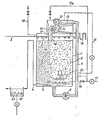
- Denoted by 1 is a denitrification reactor operated under anoxic conditions, which in the illustrated case is designed as a submerged reactor and has an inlet 2 for water to be denitrified in the upper region and an outlet 4 for denitrified water in the lower region and a carrier material 6 made of flexible in the reaction chamber open-pored plastic as Ansied- lun g s Diagram for the denitrifying bacteria is present.
- the inlet 2 is assigned a distribution device 3, which can be, for example, an open channel with a perforated bottom, for dividing the incoming water into a large number of partial flows.
- the outflow 4 for denitrified water is drawn up outside the reactor 1, so that its vertical upward length determines the height of the water to be treated in the reactor 1. If the outlet 4 is adjustable in height, ie if the vertical length of the outlet 4 is variable upwards, a partially blocked mode of operation of the reactor 1 or even the design of the reactor 1 as a trickle bed reactor is possible.
- the connection of the outlet 4 is assigned a retaining device 5 which prevents the carrier material 6 with the denitrified water from being driven off into the outlet 4.
- This can be designed as a funnel-like sieve or grid with a corresponding hole or mesh size running to the center of the reactor floor.
- a return line 7 with conveyor 8 which can be a screw conveyor, a bucket elevator or a mammoth pump, via which the carrier material can be transported back to the upper region of the reactor 1.
- the upper region of the reactor 1 is divided into two gas spaces by a separating element 9.
- a separating element 9 Below the separating element 9, an exhaust gas space forms above the water surface, in which the gas rising from the water, which is rich in nitrogen gas, collects.
- a discharge line 10 for exhaust gas is assigned to this exhaust gas space.
- a pressing device 12 is arranged as a device for loading the plastic particles with reducing gas, which can have, for example, two counter-rotating pressing rolls, the lower one of which is perforated.
- the carrier material 6 arriving via the return line 7 and the conveying device 8 is passed over a perforated chute 13, which is used for preliminary dewatering.
- the water running off is collected below the perforated slide and fed via a line 14 to the reaction space present in the lower region of the reactor 1.
- the plastic particles of the carrier material are compressed and part of the adhering bacteria and the liquid contained are pressed out. Due to the perforated design of the lower press roll, the sludge-liquid mixture removed during squeezing passes into a collecting container 15 arranged below the press rolls, to which a sludge discharge line 16 is connected, which is connected to the further treatment of the resulting sludge, for example with a thickener.
- the hole diameter of the lower press roll and the hole diameter of the chute 13 is chosen so that only the sludge-water mixture runs, but not the plastic particles can fall through. This is achieved with a hole diameter of 2 to 10 mm.
- the number of holes should advantageously be 1 to 5 per 10 cm 2 .
- the roller pressure which may be generated with the aid of springs, should be set so that a thin layer of denitrificants remains on the plastic particles even after the pressing process, so that after the plastic particles are returned to the reaction chamber of the reactor, they do not have to be denitrified again must be populated, which would affect the course of the denitrification process.
- a pressure in which the plastic particles are compressed to 5 to 30% of their original volume is sufficient.
- a pore size of the carrier material which is suitable for the suction of reducing gas, the escape of nitrogen gas formed and the passage of water is in the range from 0.1 to 5 mm with a volume of the particles from 0.1 to 75 cm 3 and a specific weight of 10 up to 200 kg / m 3 .
- the plastic particles which are loaded with reducing gas and have a thin layer of denitrifiers, then pass through gravity through a passage opening 17 in the separating element 9 and through a shaft 18 assigned to the passage opening 17 into the reaction space of the reactor 1 below the exhaust space.
- a circulating unit 23 is provided for generating this roll flow.
- the supply line 11 for reducing gas can have a branch line 19 which is connected to a gas introduction device 20 arranged in the lower region of the reaction space, as a result of which the maintenance of the cylindrical flow can be supported by reducing gas bubbles rising from the gas entry device 20.
- the amount of gas supplied via the gas introduction device 20 should only be small, since the reduction gases provided are relatively slightly water-soluble.
- an inlet for inorganic carbon can be connected to the inlet line 2 for the water to be denitrified.
- the inorganic carbon can also be added during a nitrification preceding the denitrification.
- the reactor instead of designing the reactor as a vertical reactor as shown, it is also possible to use a horizontal reactor. This should have a slowly rotating crusher in the reaction chamber, with which the carrier material is circulated and transported to the conveyor device assigned to the pressing device.
- the pressing device arranged at one end of the reactor is expediently to be followed by a conveyor belt which contains the loaded carrier material in the gas transported to the other end of the reactor and dropped there into the water to be treated above the beginning of the crowing mechanism.
- methane-containing fermentation gas is used as the reducing gas, it is also possible under certain circumstances to omit the separating element 9, which divides the upper region of the reactor into an exhaust gas space and a gas space containing the reduction gas atmosphere, since methane-containing fermentation gas is generally available inexpensively and draining part of the methane-containing fermentation gas with the exhaust gas hardly plays a role.
- a device for inflating ge. dried denitrificant cultures are present on the support material.
- the carrier material can also be provided with a thin layer of denitrifiers for the first step.
Landscapes
- Life Sciences & Earth Sciences (AREA)
- Microbiology (AREA)
- Biodiversity & Conservation Biology (AREA)
- Hydrology & Water Resources (AREA)
- Engineering & Computer Science (AREA)
- Environmental & Geological Engineering (AREA)
- Water Supply & Treatment (AREA)
- Chemical & Material Sciences (AREA)
- Organic Chemistry (AREA)
- Purification Treatments By Anaerobic Or Anaerobic And Aerobic Bacteria Or Animals (AREA)
- Biological Treatment Of Waste Water (AREA)
Priority Applications (1)
| Application Number | Priority Date | Filing Date | Title |
|---|---|---|---|
| AT84113385T ATE32872T1 (de) | 1983-11-09 | 1984-11-06 | Verfahren und vorrichtung zur biologischen denitrifikation von wasser. |
Applications Claiming Priority (2)
| Application Number | Priority Date | Filing Date | Title |
|---|---|---|---|
| DE19833340549 DE3340549A1 (de) | 1983-11-09 | 1983-11-09 | Verfahren und vorrichtung zur biologischen denitrifikation von wasser |
| DE3340549 | 1983-11-09 |
Publications (3)
| Publication Number | Publication Date |
|---|---|
| EP0142123A2 true EP0142123A2 (fr) | 1985-05-22 |
| EP0142123A3 EP0142123A3 (en) | 1986-06-04 |
| EP0142123B1 EP0142123B1 (fr) | 1988-03-09 |
Family
ID=6213886
Family Applications (1)
| Application Number | Title | Priority Date | Filing Date |
|---|---|---|---|
| EP19840113385 Expired EP0142123B1 (fr) | 1983-11-09 | 1984-11-06 | Procédé et dispositif pour la dénitrification biologique de l'eau |
Country Status (3)
| Country | Link |
|---|---|
| EP (1) | EP0142123B1 (fr) |
| AT (1) | ATE32872T1 (fr) |
| DE (2) | DE3340549A1 (fr) |
Cited By (6)
| Publication number | Priority date | Publication date | Assignee | Title |
|---|---|---|---|---|
| WO1991011396A1 (fr) * | 1990-01-23 | 1991-08-08 | Kaldnes Miljøteknologi A/S | Procede et reacteur d'epuration de l'eau |
| ES2094679A1 (es) * | 1994-02-21 | 1997-01-16 | Consejo Superior Investigacion | Procedimiento para convertir aguas residuales urbanas en facimente biodegradables. |
| WO1997008105A1 (fr) * | 1995-08-29 | 1997-03-06 | Degremont | Procede d'elimination des composes azotes et de remineralisation d'eaux faiblement mineralisees |
| LT5205B (lt) | 2002-02-18 | 2005-03-25 | Anoxkaldnes As | Biologinis vandens valymo būdas, naudojant nešiklio medžiagą |
| US10626034B2 (en) | 2013-12-02 | 2020-04-21 | Veolia Water Solutions & Technologies Support | Free-flowing carrier elements |
| EP3851416A2 (fr) | 2019-12-23 | 2021-07-21 | Tübitak | Élément de support pour le traitement d'eaux usées et procédé de modification d'un élément de support |
Families Citing this family (6)
| Publication number | Priority date | Publication date | Assignee | Title |
|---|---|---|---|---|
| SE466198B (sv) * | 1986-09-24 | 1992-01-13 | Ac Biotechnics Ab | Foerfarande foer foerbehandling av vatten paa biologisk vaeg i syfte att utfoera avgiftning av svavelfoereningar ur vattnet |
| DE3905753A1 (de) * | 1989-02-24 | 1990-08-30 | Orenstein & Koppel Ag | Verfahren und einrichtung zur denitrifikation von wasser |
| DE4011420A1 (de) * | 1990-04-09 | 1991-10-10 | Gert Schwentner | Verfahren mit tropfkoerper zur gezielten elimination der im abwasser vorhandenen stickstoffverbindungen insbesondere nitrit- und nitratstickstoff durch die biochemischen vorgaenge der denitrifikation |
| US5316668A (en) * | 1992-12-22 | 1994-05-31 | Jet, Inc. | Wastewater treatment plant and apparatus |
| US5484524A (en) * | 1993-02-01 | 1996-01-16 | Jet, Inc. | Wastewater treatment apparatus |
| EP1408008B1 (fr) * | 2002-10-10 | 2005-08-03 | VA TECH WABAG GmbH | Réacteur avec un dispositif de séparation à trois phases et procédé de séparation à trois phases |
Family Cites Families (6)
| Publication number | Priority date | Publication date | Assignee | Title |
|---|---|---|---|---|
| CH655294A5 (de) * | 1981-05-20 | 1986-04-15 | Sulzer Ag | Verfahren zur denitrifikation von wasser und anlage zur durchfuehrung des verfahrens. |
| DE3137062A1 (de) * | 1981-09-17 | 1983-03-24 | Linde Ag, 6200 Wiesbaden | "verfahren zur biologischen denitrifikation von abwasser" |
| GB2111039B (en) * | 1981-10-21 | 1985-03-20 | Hartley Simon Ltd | A process and apparatus for promoting growth of biomass |
| DE3213074A1 (de) * | 1982-04-07 | 1983-10-20 | Linde Ag, 6200 Wiesbaden | Verfahren und vorrichtung zur biologischen abwasserrreinigung |
| DE3228365A1 (de) * | 1982-07-29 | 1984-02-02 | Linde Ag, 6200 Wiesbaden | Verfahren und vorrichtung zur biologischen reinigung von abwasser |
| DE3232095A1 (de) * | 1982-08-28 | 1984-03-01 | Linde Ag, 6200 Wiesbaden | Verfahren zur denitrifikation von kohlenstofffreiem wasser |
-
1983
- 1983-11-09 DE DE19833340549 patent/DE3340549A1/de not_active Withdrawn
-
1984
- 1984-11-06 DE DE8484113385T patent/DE3469722D1/de not_active Expired
- 1984-11-06 EP EP19840113385 patent/EP0142123B1/fr not_active Expired
- 1984-11-06 AT AT84113385T patent/ATE32872T1/de not_active IP Right Cessation
Cited By (8)
| Publication number | Priority date | Publication date | Assignee | Title |
|---|---|---|---|---|
| WO1991011396A1 (fr) * | 1990-01-23 | 1991-08-08 | Kaldnes Miljøteknologi A/S | Procede et reacteur d'epuration de l'eau |
| ES2094679A1 (es) * | 1994-02-21 | 1997-01-16 | Consejo Superior Investigacion | Procedimiento para convertir aguas residuales urbanas en facimente biodegradables. |
| WO1997008105A1 (fr) * | 1995-08-29 | 1997-03-06 | Degremont | Procede d'elimination des composes azotes et de remineralisation d'eaux faiblement mineralisees |
| FR2738234A1 (fr) * | 1995-08-29 | 1997-03-07 | Degremont | Procede d'elimination des composes azotes et de remineralisation d'eaux faiblement mineralisees |
| LT5205B (lt) | 2002-02-18 | 2005-03-25 | Anoxkaldnes As | Biologinis vandens valymo būdas, naudojant nešiklio medžiagą |
| US10626034B2 (en) | 2013-12-02 | 2020-04-21 | Veolia Water Solutions & Technologies Support | Free-flowing carrier elements |
| EP3851416A2 (fr) | 2019-12-23 | 2021-07-21 | Tübitak | Élément de support pour le traitement d'eaux usées et procédé de modification d'un élément de support |
| US11541418B2 (en) | 2019-12-23 | 2023-01-03 | Turkiye Bilimsel Ve Teknolojik Arastirma Kurumu (Tubitak) | Carrier element for wastewater treatment and carrier element modification method |
Also Published As
| Publication number | Publication date |
|---|---|
| EP0142123B1 (fr) | 1988-03-09 |
| DE3469722D1 (en) | 1988-04-14 |
| EP0142123A3 (en) | 1986-06-04 |
| DE3340549A1 (de) | 1985-05-15 |
| ATE32872T1 (de) | 1988-03-15 |
Similar Documents
| Publication | Publication Date | Title |
|---|---|---|
| EP0046900B2 (fr) | Procédé et dispositif pour l'épuration des eaux usées par voie biologique | |
| EP0075298B1 (fr) | Procédé et dispositif pour la purification biologique d'eau résiduaire | |
| EP0072495B1 (fr) | Procédé et dispositif pour la purification biologique d'eau résiduaire | |
| DE3534716C2 (fr) | ||
| EP0033113B1 (fr) | Procédé et dispositif pour l'épuration par voie biologique d'eaux usées | |
| DE69313854T2 (de) | System und verfahren zur reinigung von stickstoff enthaltendem abwasser | |
| DE69104629T3 (de) | Methode und reaktor zur reinigung von wasser. | |
| EP0100007B1 (fr) | Procédé et dispositif pour la purification biologique d'eau usée | |
| DE69322132T2 (de) | Verfahren und Anlage zur anaeroben Zersetzung von organischen Abfällen | |
| EP0142123B1 (fr) | Procédé et dispositif pour la dénitrification biologique de l'eau | |
| EP0657389B1 (fr) | Procédé et dispositif pour l'épuration biologique des eaux | |
| DE3301643A1 (de) | Verfahren und vorrichtung zur biologischen reinigung von abwasser | |
| DE3827715A1 (de) | Einrichtung und verfahren zur mikrobiologischen wasseraufbereitung | |
| DD253247A5 (de) | Verfahren zur biologischen abwasserreinigung | |
| WO1998050311A1 (fr) | Procede et dispositif a bioreacteur pour traitement de dechets liquides | |
| EP0102584B1 (fr) | Procédé pour la dénitrification d'eau | |
| DE2550818B2 (de) | Verfahren und vorrichtung zur biologischen abwasserreinigung nach dem schlammbelebungsverfahren | |
| DE2033669A1 (de) | Verfahren und Vorrichtung zum Be handeln von Abwasser oder dergl | |
| EP0208253B1 (fr) | Procédé et dispositif de purification biologique d'eau usée | |
| DE19932903A1 (de) | Verfahren zur biologischen Abwasserreinigung unter Verwendung eines Wirbelbettes in einem Bioreaktor | |
| EP1829827A1 (fr) | Procédé d'épuration biologique d'eaux usées avec dégradation simultanée de composés organiques et de composés azotés | |
| DE4001855A1 (de) | Verfahren und vorrichtung zur biologischen verarbeitung von organisch belasteten, stark stickstoffhaltigen, waessrigen fluessigkeiten | |
| EP0226715B1 (fr) | Procédé et dispositif pour la dénitrification biologique d'eau | |
| DE2551902A1 (de) | Verfahren zur wahlweisen entkarbonisierung und/oder biologischen oxidation und nitrifikation von wasser | |
| RU2270173C2 (ru) | Способ биологической очистки сточных вод и устройство для его осуществления |
Legal Events
| Date | Code | Title | Description |
|---|---|---|---|
| PUAI | Public reference made under article 153(3) epc to a published international application that has entered the european phase |
Free format text: ORIGINAL CODE: 0009012 |
|
| AK | Designated contracting states |
Designated state(s): AT BE CH DE FR GB IT LI NL |
|
| PUAL | Search report despatched |
Free format text: ORIGINAL CODE: 0009013 |
|
| AK | Designated contracting states |
Kind code of ref document: A3 Designated state(s): AT BE CH DE FR GB IT LI NL |
|
| 17P | Request for examination filed |
Effective date: 19860429 |
|
| 17Q | First examination report despatched |
Effective date: 19870807 |
|
| GRAA | (expected) grant |
Free format text: ORIGINAL CODE: 0009210 |
|
| ITF | It: translation for a ep patent filed | ||
| AK | Designated contracting states |
Kind code of ref document: B1 Designated state(s): AT BE CH DE FR GB IT LI NL |
|
| REF | Corresponds to: |
Ref document number: 32872 Country of ref document: AT Date of ref document: 19880315 Kind code of ref document: T |
|
| GBT | Gb: translation of ep patent filed (gb section 77(6)(a)/1977) | ||
| REF | Corresponds to: |
Ref document number: 3469722 Country of ref document: DE Date of ref document: 19880414 |
|
| ET | Fr: translation filed | ||
| PG25 | Lapsed in a contracting state [announced via postgrant information from national office to epo] |
Ref country code: GB Effective date: 19881106 Ref country code: AT Effective date: 19881106 |
|
| PG25 | Lapsed in a contracting state [announced via postgrant information from national office to epo] |
Ref country code: LI Effective date: 19881130 Ref country code: CH Effective date: 19881130 Ref country code: BE Effective date: 19881130 |
|
| PLBE | No opposition filed within time limit |
Free format text: ORIGINAL CODE: 0009261 |
|
| STAA | Information on the status of an ep patent application or granted ep patent |
Free format text: STATUS: NO OPPOSITION FILED WITHIN TIME LIMIT |
|
| 26N | No opposition filed | ||
| BERE | Be: lapsed |
Owner name: LINDE A.G. Effective date: 19881130 |
|
| PG25 | Lapsed in a contracting state [announced via postgrant information from national office to epo] |
Ref country code: NL Effective date: 19890601 |
|
| NLV4 | Nl: lapsed or anulled due to non-payment of the annual fee | ||
| GBPC | Gb: european patent ceased through non-payment of renewal fee | ||
| PG25 | Lapsed in a contracting state [announced via postgrant information from national office to epo] |
Ref country code: FR Free format text: LAPSE BECAUSE OF NON-PAYMENT OF DUE FEES Effective date: 19890731 |
|
| REG | Reference to a national code |
Ref country code: CH Ref legal event code: PL |
|
| PG25 | Lapsed in a contracting state [announced via postgrant information from national office to epo] |
Ref country code: DE Effective date: 19890801 |
|
| REG | Reference to a national code |
Ref country code: FR Ref legal event code: ST |