EP0142135A2 - Procédé et dispositif de qualification des amortisseurs de chocs sur véhicules suspendus par ressorts, de préférence automobiles, munis de pneus élastiques - Google Patents
Procédé et dispositif de qualification des amortisseurs de chocs sur véhicules suspendus par ressorts, de préférence automobiles, munis de pneus élastiques Download PDFInfo
- Publication number
- EP0142135A2 EP0142135A2 EP84113493A EP84113493A EP0142135A2 EP 0142135 A2 EP0142135 A2 EP 0142135A2 EP 84113493 A EP84113493 A EP 84113493A EP 84113493 A EP84113493 A EP 84113493A EP 0142135 A2 EP0142135 A2 EP 0142135A2
- Authority
- EP
- European Patent Office
- Prior art keywords
- amplifier
- output
- frequency
- natural frequency
- force
- Prior art date
- Legal status (The legal status is an assumption and is not a legal conclusion. Google has not performed a legal analysis and makes no representation as to the accuracy of the status listed.)
- Granted
Links
Images

Classifications
-
- G—PHYSICS
- G01—MEASURING; TESTING
- G01M—TESTING STATIC OR DYNAMIC BALANCE OF MACHINES OR STRUCTURES; TESTING OF STRUCTURES OR APPARATUS, NOT OTHERWISE PROVIDED FOR
- G01M17/00—Testing of vehicles
- G01M17/007—Wheeled or endless-tracked vehicles
- G01M17/04—Suspension or damping
Definitions
- the invention relates to a method and a device for qualifying shock absorbers on chassis provided with elastic rubber tires, preferably on chassis of road motor vehicles.
- a deficiency of the above device is that the condition of the vibration system under test does not correspond to the real road condition, since the resonance frequency of the device which arises depends on the rigidity of the test bench spring, also on the mass of the wheel support, the unsprung mass of the chassis itself and also on that Spring of the car body is dependent. All of this causes the vibration system to be detuned, so that qualification with regard to traffic safety is only possible through correlations and with great difficulty. Knowledge of the factory-related limits of motor vehicles and shock absorbers is also essential for this. In the case of a mixed vehicle fleet, the operation of the device becomes extremely cumbersome and strains the operating personnel with a very demanding task.
- a solution is found in the Hungarian patent specification No. 176 823 described in which in the acceleration and V of the excitation frequency erzögerungsperioden felt adsohlenkraft the changes of R, from these electronically the wheel sole power mean value is calculated, then during the deceleration phase occurring at the natural frequency of the chassis minimum wheel sole force on the wheel sole power mean value in Relation, and from this the quality of the shock absorber is qualified.
- a device which has a wheel support and an excitation unit cooperating with it, the wheel support and the excitation unit being connected to one another via a two-armed lever and their pivot point being combined with a force sensor.
- the force sensor is connected to an electronic measuring unit.
- the quotient is formed from the minimum wheel sole force occurring at the natural frequency of the chassis and its mean value, and the qualification of the shock absorber is expressed in percent.
- the qualification of the shock absorber is expressed in percent.
- the aim of the invention is the further development of the above solution, ie the creation of a method and a device, in the application of which the entire qualification range, including the upper limit that can be achieved in principle, can be used.
- the method known from Hungarian Patent No. 176,823 is further developed according to the invention in that the minimum sole force is measured approximately at the maximum frequency point, furthermore a ratio is formed from the minimum sole force measured at the natural frequency of the chassis and from the minimum sole force measured at maximum frequency , and the shock absorption of the chassis is qualified according to the value obtained in each case.
- the method according to the invention can be carried out with a device which has a wheel support, an excitation unit which cooperates with it via a transmission construction, and an electronic measuring unit which is connected to a force sensor and is connected to a transmission device.
- the essence of the device according to the invention is that the excitation unit has lifting wedges which can be moved with a rotating mechanism, and which are embedded in part on the upper work surfaces designed in the lower level of the wheel support, and on the other hand on the work surfaces of the transmission structure designed as a two-support beam. wherein the upper and / or the lower work surfaces form an acute angle a with the horizontal, and one of the supports supporting the two-column beam is the force-sensing unit itself.
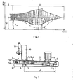
- sole forces F are plotted on the vertical axis and the time values t are plotted on the horizontal axis.
- the acceleration phase is marked with I
- the deceleration phase with II the natural frequency of the undercarriage with ⁇ o
- the associated minimum wheel sole force with F the minimum sole force with the maximum frequency with F
- the sole force mean value with F s .
- the strong continuous line means the medium shock absorption
- the thin dashed line the "strong" shock absorption
- the thin dash-dotted line the "weak” shock absorption.
- the minimum sole force value belonging to the maximum frequency was extended with a thin continuous line to the natural frequency of the chassis. This would mean the theoretically achievable maximum shock absorption, ie qualification of the quality equal to 100%.
- the maximum frequency with values between 15-24 Hz, the acceleration time I with 2 s and the deceleration time II with 20 s was selected, ie slightly larger than 1.5 times the natural frequency of the tested chassis.
- the natural frequency of the chassis on passenger cars has values between 12-15 Hz and on trucks around 10 Hz.
- the minimum sole force F m is measured at maximum frequency. This is then related to the minimum sole force F measured at the natural frequency of the chassis.
- a ratio number "k" is formed from this as follows:
- the shock absorber of the chassis is qualified (in percent).
- the device contains a wheel support 1 and an excitation unit which interacts with it via a transmission construction.
- the excitation unit consists of a rotating mechanism 3, from which this driving electric motor 6 and a fixed flywheel to the rotating shaft of the D rehmecha- mechanism 3 7.
- the rotation mechanism 3 is to be displaced in the horizontal plane lifting wedges 2 in compound, which on its upper side with work surfaces 1 A arranged on the underside of the wheel support 1 and on their underside on work surfaces 4 on the transmission structure designed as a two-support beam 4.
- the work surfaces 1 A of the wheel support 1 form an acute angle a with the horizontal; furthermore, the lever wedges 2 are provided with needle rollers on their upper and lower contact surfaces.
- One support of the two-column beam 4 forms a force-sensing unit 5 which is designed as an electrical signal transmitter and which, thanks to an electronic measuring and evaluation unit to be discussed later, offers the possibility of practically displacement-free force measurements.
- the flywheel 7 of the excitation unit has the task of ensuring a gradual reduction in frequency.
- the storage of the lifting wedges 2 on the needle rollers creates a negligible frictional resistance.
- the wheel support 1 is further provided with a vertically guiding unit 8.
- the other support of the two-support beam 4 in the present case forms a suspension joint 9, around which the beam can be tilted, for example for assembly.
- the wheel support 1 is connected to the two-support beam 4 via tension springs 12.
- the wheel of the tested motor vehicle is labeled 10 and its shock absorber is labeled with.
- a distance L of the center line between the joint 9 and the force sensing unit 5 was chosen to be 80 cm. It is thanks to this relatively large distance and the suspension joint 9; that the influence of the horizontally directed forces can be completely eliminated.
- FIG. 3 shows the electrical circuit diagram of an electronic measuring and evaluation unit of the device according to the invention, which is designated as a whole by E.
- two force sensing units 5 for left-hand and right-hand vehicle wheels
- the output lines of the preamplifiers 13 and 14 are connected to a changeover switch 15.
- the preamplifiers 13 and 14 amplify the relatively low output voltage of the force sensing units 5 from 2 mV to 0.5 V.
- a DC amplifier integrator 16 and an AC amplifier 17 are connected to the changeover switch 15 in parallel.
- a summing amplifier 18, a quotient 19 and a digital voltmeter 20 are connected in series with the DC amplifier integrator 16.
- a peak rectifier 21 and a summing amplifier 22 are connected in series with the AC amplifier 17.
- the output of the peak rectifier 21 is also connected to a SAMPLE / HOLD amplifier 23, the output of which is connected to the other input of the summing amplifier 18.
- the second input of the peak rectifier 21 has an on. 24 connected to delete, control and page selection.
- One of its outputs is connected to a motor switch designated by an arrow 25, the other output to a SAMPLE pulse generator 26.
- the output of the SAMPLE pulse generator 26 is connected to a further input of the SAMPLE / HOLD amplifier 23.
- the output of the summing amplifier 22 is connected to the other input of the quotient 19 and its other input is connected to the output of the DC amplifier integrator 16.
- the outputs of the digital voltmeter 20 are with a digital indicator 27 or. to control the rows Printer with a BCD adapter 28 in connection.
- feed unit 29 part of the electronic measuring and evaluating unit E. It is connected to the units of the electronic measuring and evaluating unit E provided with a downward-pointing arrow.
- the DC amplifier integrator 16 is used for amplification 1:10 and for averaging.
- the AC amplifier 17 likewise amplifies the changing signals for the peak rectifier 21 in a ratio of 1:10.
- the peak rectifier 21 measures the peak values of the changing signals and at the same time stores them.
- the summing amplifier 18 subtracts the stored x signal of the SAMPLE / HOLD amplifier 23 from the signal F s of the DC amplifier integrator 16 and forms the value F m therefrom (FIG. 1).
- the task of the SAMPLE pulse generator 26 is that in the present case, after the electric motor 6 (FIG. 2) has been switched off, it generates a pulse (at TTL level) of 0.5 s in length.
- the quotient 19 carries out the division F ⁇ o / F m and forwards the result to the digital voltmeter 20.
- the analog signal of the division is converted into a digital signal and the display is controlled. (During measurement 00; after 20 seconds later the value of the shock absorption, e.g. 62%).
- the digital indicator 27 and the BCD adapter unit 28 which controls the line printer, and also the supply unit 29 which supplies the stabilized supply voltage of the circuits, are known per se.
- the task of the unit 24 is to automatically delete, tax and page select the fact that it controls the time-shifted measurements ensures the time delay, the S / H - anläßt pulse and the side dial the changeover switch 15 to the right-side and left-side force-sensing unit 5 in Brings contact.
- the most important advantage of the invention is that it offers the possibility to use the entire qualification area, i.e. the theoretically maximum achievable shock absorption can be rated at 100%.
- the device can also be used universally in a heterogeneous vehicle fleet, and its construction is very simple, cheap and reliable.
Landscapes
- Physics & Mathematics (AREA)
- General Physics & Mathematics (AREA)
- Vehicle Body Suspensions (AREA)
- Vibration Dampers (AREA)
- Investigating Strength Of Materials By Application Of Mechanical Stress (AREA)
- Measurement Of Mechanical Vibrations Or Ultrasonic Waves (AREA)
- Force Measurement Appropriate To Specific Purposes (AREA)
Priority Applications (1)
| Application Number | Priority Date | Filing Date | Title |
|---|---|---|---|
| AT84113493T ATE36411T1 (de) | 1983-11-14 | 1984-11-08 | Verfahren und vorrichtung zum qualifizieren von stossdaempfern an mit elastischen reifen versehenen, gefederten fahrwerken, vorzugsweise kraftfahrzeugen. |
Applications Claiming Priority (2)
| Application Number | Priority Date | Filing Date | Title |
|---|---|---|---|
| HU388583 | 1983-11-14 | ||
| HU833885A HU186814B (en) | 1983-11-14 | 1983-11-14 | Method and apparatus for qualifying the shock absorption of sprung running gear provided with felxible tyre particularly for road motor vehicle one |
Publications (3)
| Publication Number | Publication Date |
|---|---|
| EP0142135A2 true EP0142135A2 (fr) | 1985-05-22 |
| EP0142135A3 EP0142135A3 (en) | 1986-06-04 |
| EP0142135B1 EP0142135B1 (fr) | 1988-08-10 |
Family
ID=10965909
Family Applications (1)
| Application Number | Title | Priority Date | Filing Date |
|---|---|---|---|
| EP84113493A Expired EP0142135B1 (fr) | 1983-11-14 | 1984-11-08 | Procédé et dispositif de qualification des amortisseurs de chocs sur véhicules suspendus par ressorts, de préférence automobiles, munis de pneus élastiques |
Country Status (7)
| Country | Link |
|---|---|
| US (1) | US4589273A (fr) |
| EP (1) | EP0142135B1 (fr) |
| JP (1) | JPS60166839A (fr) |
| AT (1) | ATE36411T1 (fr) |
| CA (1) | CA1213058A (fr) |
| DE (1) | DE3473349D1 (fr) |
| HU (1) | HU186814B (fr) |
Cited By (5)
| Publication number | Priority date | Publication date | Assignee | Title |
|---|---|---|---|---|
| EP0202036A3 (fr) * | 1985-04-18 | 1987-04-15 | Hiradastechnikai Gepgyar | Procédé et dispositif pour la qualification des amortisseurs d'un véhicule à moteur |
| GB2214879A (en) * | 1988-02-18 | 1989-09-13 | Thomas Rothwell | Apparatus for testing vehicle suspension linkages |
| DE3831885A1 (de) * | 1988-09-20 | 1990-03-22 | Boge Ag | Verfahren zum pruefen von schwingungsdaempfern |
| DE19519136C1 (de) * | 1995-05-30 | 1996-08-01 | Fichtel & Sachs Ag | Stoßdämpferprüfgerät |
| DE19823374A1 (de) * | 1998-05-18 | 1999-12-09 | Bosch Gmbh Robert | Radaufhängungs-Tester |
Families Citing this family (5)
| Publication number | Priority date | Publication date | Assignee | Title |
|---|---|---|---|---|
| DE3925616A1 (de) * | 1989-08-02 | 1991-02-07 | Pietzsch Ibp Gmbh | Versuchstraeger |
| NL9001989A (nl) * | 1990-09-10 | 1992-04-01 | Analogic Eng Bv | Inrichting voor het beproeven van de wielophanging van een voertuig. |
| GB9203651D0 (en) * | 1992-02-19 | 1992-04-08 | Lotus Car | Suspension testing apparatus and method |
| US5369974A (en) * | 1992-11-10 | 1994-12-06 | Hunter Engineering Company | Suspension tester and method |
| WO2015182168A1 (fr) * | 2014-05-28 | 2015-12-03 | 株式会社ショーワ | Procédé et système d'inspection de mécanisme variateur de force d'amortissement, et procédé d'inspection de dispositif d'amortissement de pression |
Family Cites Families (9)
| Publication number | Priority date | Publication date | Assignee | Title |
|---|---|---|---|---|
| US3282088A (en) * | 1963-09-09 | 1966-11-01 | Stephen C Joannou | Shock forming machine |
| FR2068853A5 (fr) * | 1969-10-15 | 1971-09-03 | Brisard Gerard | |
| US3937058A (en) * | 1971-07-03 | 1976-02-10 | Maschinenfabrik Koeppern & Co. Kg | Method of determining the behaviour of a shock absorber in the sprung mass system of a vehicle and a jig for performing the method |
| DE2423978C3 (de) * | 1974-05-18 | 1981-07-23 | Maschinenfabrik Köppern GmbH & Co KG, 4320 Hattingen | Vorrichtung zur Bestimmung des Verhaltens eines Stoßdämpfers in den Massen-Feder-Systemen eines Kraftfahrzeuges |
| US3855841A (en) * | 1973-02-23 | 1974-12-24 | L Hunter | Method of testing vehicle shock absorbers and apparatus therefor |
| IT992509B (it) * | 1973-06-11 | 1975-09-30 | Buzzi Luigi | Apparecchio di controllo della efficenza degli ammortizzatori dei vecoli |
| DE2445406C2 (de) * | 1974-09-23 | 1980-02-14 | Gebr. Hofmann Gmbh & Co Kg, Maschinenfabrik, 6100 Darmstadt | Verfahren und Vorrichtung zum Prüfen von Schwingungsdampfern eines Fahrzeuges |
| US4103532A (en) * | 1976-06-10 | 1978-08-01 | Carlo Buzzi | Device for measuring the damping effect of motor vehicle suspensions |
| DE3071395D1 (en) * | 1980-10-07 | 1986-03-13 | Kozlekedestudomanyi Intezet | Method and device for qualifying the shock absorbers of sprung vehicles equipped with resilient tyres, especially power-driven road vehicles |
-
1983
- 1983-11-14 HU HU833885A patent/HU186814B/hu unknown
-
1984
- 1984-11-08 DE DE8484113493T patent/DE3473349D1/de not_active Expired
- 1984-11-08 AT AT84113493T patent/ATE36411T1/de not_active IP Right Cessation
- 1984-11-08 EP EP84113493A patent/EP0142135B1/fr not_active Expired
- 1984-11-13 CA CA000467623A patent/CA1213058A/fr not_active Expired
- 1984-11-14 US US06/671,448 patent/US4589273A/en not_active Expired - Fee Related
- 1984-11-14 JP JP59240396A patent/JPS60166839A/ja active Pending
Cited By (7)
| Publication number | Priority date | Publication date | Assignee | Title |
|---|---|---|---|---|
| EP0202036A3 (fr) * | 1985-04-18 | 1987-04-15 | Hiradastechnikai Gepgyar | Procédé et dispositif pour la qualification des amortisseurs d'un véhicule à moteur |
| GB2214879A (en) * | 1988-02-18 | 1989-09-13 | Thomas Rothwell | Apparatus for testing vehicle suspension linkages |
| GB2214879B (en) * | 1988-02-18 | 1992-03-11 | Thomas Rothwell | Test apparatus |
| DE3831885A1 (de) * | 1988-09-20 | 1990-03-22 | Boge Ag | Verfahren zum pruefen von schwingungsdaempfern |
| DE19519136C1 (de) * | 1995-05-30 | 1996-08-01 | Fichtel & Sachs Ag | Stoßdämpferprüfgerät |
| US5665901A (en) * | 1995-05-30 | 1997-09-09 | Fichtel & Sachs Ag | Shock absorber testing device |
| DE19823374A1 (de) * | 1998-05-18 | 1999-12-09 | Bosch Gmbh Robert | Radaufhängungs-Tester |
Also Published As
| Publication number | Publication date |
|---|---|
| CA1213058A (fr) | 1986-10-21 |
| US4589273A (en) | 1986-05-20 |
| EP0142135A3 (en) | 1986-06-04 |
| JPS60166839A (ja) | 1985-08-30 |
| EP0142135B1 (fr) | 1988-08-10 |
| HU186814B (en) | 1985-09-30 |
| DE3473349D1 (en) | 1988-09-15 |
| ATE36411T1 (de) | 1988-08-15 |
Similar Documents
| Publication | Publication Date | Title |
|---|---|---|
| EP2136195B1 (fr) | Procédé et dispositif d'essai d'un amortisseur de chocs intégré dans un véhicule automobile | |
| DE3437661C2 (de) | Verfahren zum Bestimmen reparaturbedürftiger Bauteile einer Fahrzeugeinheit | |
| DE3151254C2 (de) | Prüfvorrichtung für den Reifenluftdruck von Rädern an Fahrzeugen und Verfahren für eine derartige Vorrichtung | |
| EP0241493B1 (fr) | Dispositif avec au moins deux liens rigides | |
| EP0232855B1 (fr) | Méthode et dispositif pour tester des roues de véhicule sur rails | |
| EP0611960B1 (fr) | Méthod pour examiner un amortisseur de vibration d'un véhicule | |
| EP0280785B1 (fr) | Banc d'essai des freins de véhicules, en particulier d'automobiles à dispositif d'anti-blocage des freins | |
| DE3632919A1 (de) | Verfahren zur daempfkraftverstellung von kraftfahrzeugen | |
| DE102004021488B4 (de) | Prüfstand für Drehgestelle und/oder Radsätze von Schienenfahrzeugen | |
| EP0142135A2 (fr) | Procédé et dispositif de qualification des amortisseurs de chocs sur véhicules suspendus par ressorts, de préférence automobiles, munis de pneus élastiques | |
| EP2101156A2 (fr) | Procédé et dispositif destinés à la surveillance de systèmes de réglage de châssis | |
| EP0299217A2 (fr) | Banc d'épreuve à vibration pour véhicules en particulier pour voitures | |
| DE19635194C1 (de) | Fahrzeugprüfvorrichtung | |
| DE2414171B2 (de) | Meßgerät zur Messung der Dämpfungswirksamkeit von Stoßdömpfern | |
| DE4432286A1 (de) | Vorrichtung und Verfahren zum Prüfen von Stoßdämpfern von Fahrzeugen | |
| EP0049303B1 (fr) | Procédé et appareil pour vérifier le fonctionnement d'amortisseurs montés dans des véhicules | |
| DE1919775C3 (de) | Verfahren und Vorrichtung zur Feststellung der Beschaffenheit der Lage eines Gleises | |
| DE3715460C1 (en) | Wind tunnel balance and method for operating it | |
| EP3601008B1 (fr) | Dispositif servant à mesurer des forces d'appui au sol d'un véhicule sur rails | |
| DE2362661A1 (de) | Verfahren zur pruefung der funktionsfaehigkeit von stossdaempfern | |
| EP1207091A1 (fr) | Dispositif pour détecter des non-uniformités dans les roues de véhicules ferroviaires | |
| DE2851719A1 (de) | Vorrichtung zur ermittlung des spiels in radaufhaengungen von kraftfahrzeugen | |
| DE3826196C2 (fr) | ||
| DE3023295A1 (de) | Verfahren und vorrichtung zur funktionspruefung von fahrzeug-schwingungsdaempfen | |
| DE2321012A1 (de) | Vorrichtung und verfahren zum messen und einstellen der radaufhaengung von kraftfahrzeugen |
Legal Events
| Date | Code | Title | Description |
|---|---|---|---|
| PUAI | Public reference made under article 153(3) epc to a published international application that has entered the european phase |
Free format text: ORIGINAL CODE: 0009012 |
|
| AK | Designated contracting states |
Designated state(s): AT BE CH DE FR GB IT LI LU NL SE |
|
| RTI1 | Title (correction) | ||
| PUAL | Search report despatched |
Free format text: ORIGINAL CODE: 0009013 |
|
| AK | Designated contracting states |
Kind code of ref document: A3 Designated state(s): AT BE CH DE FR GB IT LI LU NL SE |
|
| 17P | Request for examination filed |
Effective date: 19860624 |
|
| 17Q | First examination report despatched |
Effective date: 19871103 |
|
| GRAA | (expected) grant |
Free format text: ORIGINAL CODE: 0009210 |
|
| AK | Designated contracting states |
Kind code of ref document: B1 Designated state(s): AT BE CH DE FR GB IT LI LU NL SE |
|
| PG25 | Lapsed in a contracting state [announced via postgrant information from national office to epo] |
Ref country code: SE Effective date: 19880810 Ref country code: IT Free format text: LAPSE BECAUSE OF FAILURE TO SUBMIT A TRANSLATION OF THE DESCRIPTION OR TO PAY THE FEE WITHIN THE PRESCRIBED TIME-LIMIT;WARNING: LAPSES OF ITALIAN PATENTS WITH EFFECTIVE DATE BEFORE 2007 MAY HAVE OCCURRED AT ANY TIME BEFORE 2007. THE CORRECT EFFECTIVE DATE MAY BE DIFFERENT FROM THE ONE RECORDED. Effective date: 19880810 Ref country code: GB Free format text: LAPSE BECAUSE OF NON-PAYMENT OF DUE FEES Effective date: 19880810 Ref country code: FR Free format text: THE PATENT HAS BEEN ANNULLED BY A DECISION OF A NATIONAL AUTHORITY Effective date: 19880810 Ref country code: BE Effective date: 19880810 |
|
| REF | Corresponds to: |
Ref document number: 36411 Country of ref document: AT Date of ref document: 19880815 Kind code of ref document: T |
|
| REF | Corresponds to: |
Ref document number: 3473349 Country of ref document: DE Date of ref document: 19880915 |
|
| PG25 | Lapsed in a contracting state [announced via postgrant information from national office to epo] |
Ref country code: AT Effective date: 19881108 |
|
| PG25 | Lapsed in a contracting state [announced via postgrant information from national office to epo] |
Ref country code: LU Free format text: LAPSE BECAUSE OF NON-PAYMENT OF DUE FEES Effective date: 19881130 Ref country code: LI Effective date: 19881130 Ref country code: CH Effective date: 19881130 |
|
| EN | Fr: translation not filed | ||
| GBV | Gb: ep patent (uk) treated as always having been void in accordance with gb section 77(7)/1977 [no translation filed] | ||
| PLBE | No opposition filed within time limit |
Free format text: ORIGINAL CODE: 0009261 |
|
| STAA | Information on the status of an ep patent application or granted ep patent |
Free format text: STATUS: NO OPPOSITION FILED WITHIN TIME LIMIT |
|
| 26N | No opposition filed | ||
| REG | Reference to a national code |
Ref country code: CH Ref legal event code: PL |
|
| PGFP | Annual fee paid to national office [announced via postgrant information from national office to epo] |
Ref country code: NL Payment date: 19901130 Year of fee payment: 7 |
|
| PGFP | Annual fee paid to national office [announced via postgrant information from national office to epo] |
Ref country code: DE Payment date: 19910130 Year of fee payment: 7 |
|
| PG25 | Lapsed in a contracting state [announced via postgrant information from national office to epo] |
Ref country code: NL Effective date: 19920601 |
|
| NLV4 | Nl: lapsed or anulled due to non-payment of the annual fee | ||
| PG25 | Lapsed in a contracting state [announced via postgrant information from national office to epo] |
Ref country code: DE Effective date: 19920801 |