EP0142170A2 - Convertisseur pour la synthèse de l'ammoniac - Google Patents
Convertisseur pour la synthèse de l'ammoniac Download PDFInfo
- Publication number
- EP0142170A2 EP0142170A2 EP84113777A EP84113777A EP0142170A2 EP 0142170 A2 EP0142170 A2 EP 0142170A2 EP 84113777 A EP84113777 A EP 84113777A EP 84113777 A EP84113777 A EP 84113777A EP 0142170 A2 EP0142170 A2 EP 0142170A2
- Authority
- EP
- European Patent Office
- Prior art keywords
- catalyst bed
- fluid communication
- bed
- converter
- disposed
- Prior art date
- Legal status (The legal status is an assumption and is not a legal conclusion. Google has not performed a legal analysis and makes no representation as to the accuracy of the status listed.)
- Granted
Links
Images

Classifications
-
- C—CHEMISTRY; METALLURGY
- C01—INORGANIC CHEMISTRY
- C01C—AMMONIA; CYANOGEN; COMPOUNDS THEREOF
- C01C1/00—Ammonia; Compounds thereof
- C01C1/02—Preparation, purification or separation of ammonia
- C01C1/04—Preparation of ammonia by synthesis
- C01C1/0405—Preparation of ammonia by synthesis from N2 and H2 in presence of a catalyst
- C01C1/0417—Preparation of ammonia by synthesis from N2 and H2 in presence of a catalyst characterised by the synthesis reactor, e.g. arrangement of catalyst beds and heat exchangers in the reactor
- C01C1/0423—Cold wall reactors
-
- B—PERFORMING OPERATIONS; TRANSPORTING
- B01—PHYSICAL OR CHEMICAL PROCESSES OR APPARATUS IN GENERAL
- B01J—CHEMICAL OR PHYSICAL PROCESSES, e.g. CATALYSIS OR COLLOID CHEMISTRY; THEIR RELEVANT APPARATUS
- B01J8/00—Chemical or physical processes in general, conducted in the presence of fluids and solid particles; Apparatus for such processes
- B01J8/0005—Catalytic processes under superatmospheric pressure
-
- B—PERFORMING OPERATIONS; TRANSPORTING
- B01—PHYSICAL OR CHEMICAL PROCESSES OR APPARATUS IN GENERAL
- B01J—CHEMICAL OR PHYSICAL PROCESSES, e.g. CATALYSIS OR COLLOID CHEMISTRY; THEIR RELEVANT APPARATUS
- B01J8/00—Chemical or physical processes in general, conducted in the presence of fluids and solid particles; Apparatus for such processes
- B01J8/02—Chemical or physical processes in general, conducted in the presence of fluids and solid particles; Apparatus for such processes with stationary particles, e.g. in fixed beds
- B01J8/04—Chemical or physical processes in general, conducted in the presence of fluids and solid particles; Apparatus for such processes with stationary particles, e.g. in fixed beds the fluid passing successively through two or more beds
- B01J8/0446—Chemical or physical processes in general, conducted in the presence of fluids and solid particles; Apparatus for such processes with stationary particles, e.g. in fixed beds the fluid passing successively through two or more beds the flow within the beds being predominantly vertical
- B01J8/0449—Chemical or physical processes in general, conducted in the presence of fluids and solid particles; Apparatus for such processes with stationary particles, e.g. in fixed beds the fluid passing successively through two or more beds the flow within the beds being predominantly vertical in two or more cylindrical beds
- B01J8/0453—Chemical or physical processes in general, conducted in the presence of fluids and solid particles; Apparatus for such processes with stationary particles, e.g. in fixed beds the fluid passing successively through two or more beds the flow within the beds being predominantly vertical in two or more cylindrical beds the beds being superimposed one above the other
-
- B—PERFORMING OPERATIONS; TRANSPORTING
- B01—PHYSICAL OR CHEMICAL PROCESSES OR APPARATUS IN GENERAL
- B01J—CHEMICAL OR PHYSICAL PROCESSES, e.g. CATALYSIS OR COLLOID CHEMISTRY; THEIR RELEVANT APPARATUS
- B01J8/00—Chemical or physical processes in general, conducted in the presence of fluids and solid particles; Apparatus for such processes
- B01J8/02—Chemical or physical processes in general, conducted in the presence of fluids and solid particles; Apparatus for such processes with stationary particles, e.g. in fixed beds
- B01J8/04—Chemical or physical processes in general, conducted in the presence of fluids and solid particles; Apparatus for such processes with stationary particles, e.g. in fixed beds the fluid passing successively through two or more beds
- B01J8/0492—Feeding reactive fluids
-
- B—PERFORMING OPERATIONS; TRANSPORTING
- B01—PHYSICAL OR CHEMICAL PROCESSES OR APPARATUS IN GENERAL
- B01J—CHEMICAL OR PHYSICAL PROCESSES, e.g. CATALYSIS OR COLLOID CHEMISTRY; THEIR RELEVANT APPARATUS
- B01J2208/00—Processes carried out in the presence of solid particles; Reactors therefor
- B01J2208/00008—Controlling the process
- B01J2208/00017—Controlling the temperature
- B01J2208/00106—Controlling the temperature by indirect heat exchange
- B01J2208/00168—Controlling the temperature by indirect heat exchange with heat exchange elements outside the bed of solid particles
- B01J2208/00212—Plates; Jackets; Cylinders
-
- Y—GENERAL TAGGING OF NEW TECHNOLOGICAL DEVELOPMENTS; GENERAL TAGGING OF CROSS-SECTIONAL TECHNOLOGIES SPANNING OVER SEVERAL SECTIONS OF THE IPC; TECHNICAL SUBJECTS COVERED BY FORMER USPC CROSS-REFERENCE ART COLLECTIONS [XRACs] AND DIGESTS
- Y02—TECHNOLOGIES OR APPLICATIONS FOR MITIGATION OR ADAPTATION AGAINST CLIMATE CHANGE
- Y02P—CLIMATE CHANGE MITIGATION TECHNOLOGIES IN THE PRODUCTION OR PROCESSING OF GOODS
- Y02P20/00—Technologies relating to chemical industry
- Y02P20/50—Improvements relating to the production of bulk chemicals
- Y02P20/52—Improvements relating to the production of bulk chemicals using catalysts, e.g. selective catalysts
Definitions
- ammonia converters are large, complex items of equipment and that steps toward more efficient, less costly design are needed.
- a vertical, cold wall, three bed converter having a single heat exchanger is provided.
- the three axial flow catalyst beds are arranged vertically within the cylindrical inner shell of the converter. Gas flows in series through the shell annulus, the cold exchange side of the indirect heat exchanger, the upper catalyst bed, the hot exchange side of the indirect heat exchanger and, finally,in parallel through the intermediate and lower catalyst beds. Outlet gas from the intermediate and lower beds is preferably recombined for common discharge through a single gas outlet means.
- the converter of the invention employs no external quench gas between or within the catalyst beds. That is to say, it is a full flow converter in which the outlet portion of the hot exchange side of the indirect heat exchanger is in exclusive flow communication with respective inlet portions of the intermediate and lower catalyst beds. Accordingly, all of the converter outlet gas from the intermediate and lower catalyst beds passes initially through the upper catalyst bed.
- the catalyst beds are laterally defined by respective portions of the cylindrical inner shell and are supported by foraminous partitions which, in turn, are supported by the inner shell.
- An intermediate fluid barrier means or partition is disposed between the upper and intermediate catalyst beds to prevent direct gas flow therebetween.
- a lower fluid barrier means or partition is disposed between the intermediate and lower catalyst beds to prevent direct gas flow therebetween.
- Axial conduits or other flow communication means are disposed in the catalyst beds to route gas in accordance with the process gas flow described above.
- the single indirect heat exchanger is located adjacently above the upper catalyst bed. In another embodiment of the invention, the single heat exchanger is located adjacently below the upper catalyst bed.
- the intermediate and lower catalyst beds have decreased vulnerability to overheating as conversion to ammonia increases and, therefore, may contain more catalyst than the upper bed.
- the intermediate and lower catalyst beds contain substantially equal volumes of catalyst and catalyst volume of the upper bed is from about 35 to about 65 percent of catalyst volume in either the intermediate or lower catalyst bed.
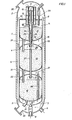
- the vertical converter is contained within cylindrical pressure shell 1 which is attached to top outer head 2 and bottom outer head 3.
- a cylindrical inner shell 4 is disposed within and parallel to the pressure shell and is spaced therefrom to form shell annulus 5.
- Top inner head 6 and bottom inner head 7 are attached to the inner shell.
- Gas outlet means 8 disposed in bottom outer head 3 and bottom inner head 7 provides fluid communication between the internal portion of the bottom inner head and external piping for conversion product gas and also provides a fluid barrier between conversion product gas and reactant synthesis gas introduced to the shell annulus through gas inlet means 9 which is also disposed in-the bottom outer head.
- a shell and tube heat exchanger 10 is mounted in the top inner head 6.
- the exchanger tube side 11 is the cold heat exchange side for reactant synthesis gas incoming from the shell annulus and the exchanger shell side 12 is the hot heat exchange side for partially converted gas.
- the exchanger shell is contiguous with the top inner head to effect a fluid barrier between the shell annulus and the inside of inner shell 4.
- Upper catalyst bed 13 is located adjacently below the single heat exchanger and is contained and defined in part by the upper end of the cylindrical inner shell and supported by foraminous dished head 32 which is contiguous with the inner shell.
- the upper bed has an inlet portion 14 formed in part by the top surface of the catalyst bed and an outlet portion 15 below and adjacent to foraminous dished head 32.
- Lower catalyst bed 16 having inlet portion 17 and outlet portion 18 as well as intermediate bed 19 having inlet portion 20 and outlet portion 21 are arranged similarly to the upper catalyst bed.
- the lower and intermediate catalyst bed volumes are substantially equal and the upper catalyst bed volume is from about 35 to about 65 percent of the intermediate bed volume.
- Intermediate partition 22 is a dished head contiguous with cylindrical inner shell 4 which separates and forms an intermediate fluid barrier between outlet portion 15 of the upper catalyst bed and inlet portion 20 of the intermediate catalyst bed.
- lower partition 23 forms a lower fluid barrier between outlet portion 21 of the intermediate catalyst bed and inlet portion 17 of the lower catalyst bed.
- Axial upper conduit 24 is disposed centrally within the upper catalyst bed and axial, inner, upper conduit 25 is disposed centrally within it to form conduit annulus 26.
- the conduit annulus provides fluid communication between outlet portion 15 of the upper catalyst bed and inlet end of the hot heat exchange side 12 of the indirect heat exchanger.
- the axial, inner, upper conduit 25 provides fluid communication between the outlet end of the hot heat exchange side 12 of the exchanger and inlet portion 20 of the intermediate catalyst bed.
- Axial intermediate conduit 27 is disposed within the intermediate catalyst bed and provides fluid communication between the inlet portion 20 of the intermediate catalyst bed and inlet portion 17 of the lower catalyst bed.
- Axial lower conduit 28 is disposed within the lower catalyst bed and provides fluid communication between outlet portion 21 of the intermediate catalyst bed and outlet portion 18 of the lower catalyst bed.
- the foregoing arrangement provides for flow of reactant synthesis gas into the converter via gas inlet 9, upwardly through shell annulus 5 to cool the pressure shell and into the cold exchange side 11 of the heat exchanger where the gas is heated to conversion temperature by indirect heat exchange with partially converted gas in the shell side.
- the heated reaction synthesis gas from the tubes 11 is preferably mixed with from about 1 to about 20 volume % of supplemental reaction synthesis gas introduced through injection means 29 for the purpose.of precise temperature control.
- the reaction synthesis gas then flows axially downward through the upper catalyst bed 13, then upwardly via conduit annulus 26 and through hot exchange side 12 of the exchanger where at least a portion of exothermic reaction heat is removed from the now partially converted gas.
- manways 30 are provided for inspection access and chutes 31 are provided for catalyst loading and unloading.
- the reference numerals have substantially the same indentification and purpose as in Figure 1.
- the single indirect heat exchanger 10 is located adjacently below the upper catalyst bed 13 and the cold exchange side 11 is now the shell side of the exchanger.
- the inner, upper conduit is contiguous at its upper extremity with the top inner head 6 and provides fluid communication between the shell annulus 5 and the cold exchange side 11 via upper head annulus 35.
- the conduit annulus 26 provides fluid communication between the cold heat exchange side 11 and the inlet portion 14 of the upper catalyst bed.
Landscapes
- Chemical & Material Sciences (AREA)
- Chemical Kinetics & Catalysis (AREA)
- Organic Chemistry (AREA)
- Analytical Chemistry (AREA)
- Inorganic Chemistry (AREA)
- Devices And Processes Conducted In The Presence Of Fluids And Solid Particles (AREA)
Applications Claiming Priority (2)
| Application Number | Priority Date | Filing Date | Title |
|---|---|---|---|
| US06/550,858 US4482523A (en) | 1983-11-14 | 1983-11-14 | Ammonia synthesis converter |
| US550858 | 1983-11-14 |
Publications (3)
| Publication Number | Publication Date |
|---|---|
| EP0142170A2 true EP0142170A2 (fr) | 1985-05-22 |
| EP0142170A3 EP0142170A3 (en) | 1985-08-21 |
| EP0142170B1 EP0142170B1 (fr) | 1987-09-02 |
Family
ID=24198858
Family Applications (1)
| Application Number | Title | Priority Date | Filing Date |
|---|---|---|---|
| EP84113777A Expired EP0142170B1 (fr) | 1983-11-14 | 1984-11-14 | Convertisseur pour la synthèse de l'ammoniac |
Country Status (5)
| Country | Link |
|---|---|
| US (1) | US4482523A (fr) |
| EP (1) | EP0142170B1 (fr) |
| JP (1) | JPH0662293B2 (fr) |
| CA (1) | CA1209789A (fr) |
| DE (1) | DE3465705D1 (fr) |
Cited By (2)
| Publication number | Priority date | Publication date | Assignee | Title |
|---|---|---|---|---|
| EP0297474B1 (fr) * | 1987-07-03 | 1992-04-01 | Ammonia Casale S.A. | Procédé de synthèse hétérogène et réacteurs apparentés |
| RU2137538C1 (ru) * | 1993-10-29 | 1999-09-20 | Аммониа Казале С.А. | Способ модернизации реактора для гетерогенного экзотермического синтеза и способ повышения его эффективности |
Families Citing this family (15)
| Publication number | Priority date | Publication date | Assignee | Title |
|---|---|---|---|---|
| US4753779A (en) * | 1985-08-02 | 1988-06-28 | The Boeing Company | Sliding tray reactor |
| US4988486A (en) * | 1985-08-02 | 1991-01-29 | The Boeing Company | Hydrogen generator |
| US4842844A (en) * | 1985-08-02 | 1989-06-27 | The Boeing Company | Method of generating hydrogen |
| US4735780A (en) * | 1986-07-15 | 1988-04-05 | The M. W. Kellogg Company | Ammonia synthesis converter |
| JPS6314533U (fr) * | 1986-07-15 | 1988-01-30 | ||
| CN2077087U (zh) * | 1990-08-03 | 1991-05-15 | 中国石油化工总公司湖北化肥厂 | 大型氨厂转化炉燃烧空气节能装置 |
| US5250270A (en) * | 1992-07-17 | 1993-10-05 | The M. W. Kellogg Company | Catalytic reactor bed |
| US5670116A (en) * | 1995-12-05 | 1997-09-23 | Exxon Research & Engineering Company | Hydroprocessing reactor with enhanced product selectivity |
| US7578883B1 (en) * | 2001-08-29 | 2009-08-25 | Lsi Corporation | Arrangement and method for abating effluent from a process |
| US7867460B2 (en) | 2007-11-26 | 2011-01-11 | Kellogg Brown & Root Llc | Efficiency of ammonia processes |
| US8197785B2 (en) * | 2008-02-27 | 2012-06-12 | Kellogg Brown & Root Llc | Split flow contactor |
| AU2016238957B2 (en) * | 2008-02-27 | 2018-09-13 | Kellogg Brown & Root Llc | Split flow contactor |
| AU2014206238B2 (en) * | 2008-02-27 | 2016-07-07 | Kellogg Brown & Root Llc | Split flow contactor |
| WO2013181443A1 (fr) * | 2012-05-30 | 2013-12-05 | Kellogg Brown & Root Llc | Contacteur à écoulements divisés |
| AR113648A1 (es) | 2017-12-20 | 2020-05-27 | Haldor Topsoe As | Convertidor de flujo axial adiabático |
Family Cites Families (14)
| Publication number | Priority date | Publication date | Assignee | Title |
|---|---|---|---|---|
| US2512586A (en) * | 1945-09-04 | 1950-06-20 | Commercial Solvents Corp | Process and apparatus for carrying out exothermic chemical reactions |
| US2887365A (en) * | 1955-02-21 | 1959-05-19 | Belge Produits Chimiques Sa | Catalytic reactor |
| US3031274A (en) * | 1957-02-06 | 1962-04-24 | Uhde Gmbh Friedrich | Apparatus for catalytic highpressure syntheses |
| US3366461A (en) * | 1964-05-11 | 1968-01-30 | Chemical Construction Corp | Apparatus for exothermic catalytic reactions |
| CH471747A (de) * | 1966-04-25 | 1969-04-30 | F Braun Wilhelm | Verfahren zur synthetischen Gewinnung von Ammoniak |
| US3475136A (en) * | 1966-05-09 | 1969-10-28 | Pullman Inc | Apparatus for effecting catalytic reactions at elevated pressures |
| DE1667323C3 (de) * | 1967-11-21 | 1974-11-21 | Friedrich Uhde Gmbh, 4600 Dortmund | Vorrichtung zur Durchführung exothermer katalytischer Gasreaktionen für die Ammoniak- und Methanol-Synthese |
| AT289036B (de) * | 1968-04-13 | 1971-03-25 | Uhde Gmbh Friedrich | Verfahren zur Reaktionswärmegewinnung bei der katalytischen Hochdruck-Synthese, insbesondere der Ammoniak- und Methanol-Synthese |
| GB1307845A (en) * | 1969-05-28 | 1973-02-21 | Ici Ltd | Reactor |
| GB1601475A (en) * | 1977-04-18 | 1981-10-28 | Ici Ltd | Catalytic reactor |
| US4230669A (en) * | 1978-07-17 | 1980-10-28 | Pullman Incorporated | Radial ammonia converter |
| US4372920A (en) * | 1979-07-13 | 1983-02-08 | Ammonia Casale S.A. | Axial-radial reactor for heterogeneous synthesis |
| EP0026057B1 (fr) * | 1979-09-14 | 1984-03-14 | Imperial Chemical Industries Plc | Réacteur de synthèse et procédés |
| DE3266054D1 (en) * | 1981-11-19 | 1985-10-10 | Ici Plc | Synthesis process and reactor |
-
1983
- 1983-11-14 US US06/550,858 patent/US4482523A/en not_active Expired - Fee Related
-
1984
- 1984-09-27 CA CA000464144A patent/CA1209789A/fr not_active Expired
- 1984-10-11 JP JP59213249A patent/JPH0662293B2/ja not_active Expired - Lifetime
- 1984-11-14 DE DE8484113777T patent/DE3465705D1/de not_active Expired
- 1984-11-14 EP EP84113777A patent/EP0142170B1/fr not_active Expired
Cited By (2)
| Publication number | Priority date | Publication date | Assignee | Title |
|---|---|---|---|---|
| EP0297474B1 (fr) * | 1987-07-03 | 1992-04-01 | Ammonia Casale S.A. | Procédé de synthèse hétérogène et réacteurs apparentés |
| RU2137538C1 (ru) * | 1993-10-29 | 1999-09-20 | Аммониа Казале С.А. | Способ модернизации реактора для гетерогенного экзотермического синтеза и способ повышения его эффективности |
Also Published As
| Publication number | Publication date |
|---|---|
| EP0142170B1 (fr) | 1987-09-02 |
| CA1209789A (fr) | 1986-08-19 |
| JPS60108319A (ja) | 1985-06-13 |
| EP0142170A3 (en) | 1985-08-21 |
| JPH0662293B2 (ja) | 1994-08-17 |
| US4482523A (en) | 1984-11-13 |
| DE3465705D1 (en) | 1987-10-08 |
Similar Documents
| Publication | Publication Date | Title |
|---|---|---|
| US4482523A (en) | Ammonia synthesis converter | |
| KR102688873B1 (ko) | 냉각 축 유동 변환기 | |
| EP0256299B1 (fr) | Convertisseur de synthèse d'ammoniac | |
| US8007734B2 (en) | Isothermal reactor | |
| DK167242B1 (da) | Apparat og fremgangsmaade til exoterme reaktioner | |
| US4735780A (en) | Ammonia synthesis converter | |
| EP1839735B1 (fr) | Reacteur echangeur de chaleur tubulaire transversal et procede de synthese catalytique dans celui-ci | |
| EP2473267B1 (fr) | Réacteur isothermique à calandre vertical et son utilisation pour la synthèse de methanol | |
| US3663179A (en) | Apparatus for exothermic catalytic reactions | |
| US6299849B1 (en) | Method for in-situ modernization of a heterogeneous exothermic synthesis reactor | |
| US7279138B2 (en) | Horizontal chemical reactor, in particular for methanol synthesis | |
| PL111651B1 (en) | Converter for ammonia synthesis | |
| US6214296B1 (en) | Method of catalytic reaction carried out near the optimal temperature and an apparatus for the method | |
| JPH0376976B2 (fr) | ||
| US3372988A (en) | Process and apparatus for performing reactions in the gaseous phase | |
| IL28758A (en) | Reactor for the continuous performance of exothermic catalyzed reactions in the gas phase under high pressure | |
| US3892535A (en) | Ammonia synthesis converter | |
| US5152977A (en) | Process for exothermic heterogeneous synthesis with external recovery of heat | |
| EP0254936A2 (fr) | Convertisseur de synthèse d'ammoniac | |
| CA1193075A (fr) | Reacteur chimique | |
| EP0253350A2 (fr) | Convertisseur de synthèse d'ammoniac | |
| US4942022A (en) | Catalytic reactor | |
| KR102660387B1 (ko) | 단열 축 유동 변환기 | |
| US3498752A (en) | Apparatus for exothermic catalytic reactions | |
| US3492099A (en) | Parallel gas flow reactor |
Legal Events
| Date | Code | Title | Description |
|---|---|---|---|
| PUAI | Public reference made under article 153(3) epc to a published international application that has entered the european phase |
Free format text: ORIGINAL CODE: 0009012 |
|
| AK | Designated contracting states |
Designated state(s): DE FR GB IT NL |
|
| PUAL | Search report despatched |
Free format text: ORIGINAL CODE: 0009013 |
|
| AK | Designated contracting states |
Designated state(s): DE FR GB IT NL |
|
| 17P | Request for examination filed |
Effective date: 19850927 |
|
| 17Q | First examination report despatched |
Effective date: 19861114 |
|
| GRAA | (expected) grant |
Free format text: ORIGINAL CODE: 0009210 |
|
| AK | Designated contracting states |
Kind code of ref document: B1 Designated state(s): DE FR GB IT NL |
|
| ITF | It: translation for a ep patent filed | ||
| REF | Corresponds to: |
Ref document number: 3465705 Country of ref document: DE Date of ref document: 19871008 |
|
| ET | Fr: translation filed | ||
| PLBE | No opposition filed within time limit |
Free format text: ORIGINAL CODE: 0009261 |
|
| STAA | Information on the status of an ep patent application or granted ep patent |
Free format text: STATUS: NO OPPOSITION FILED WITHIN TIME LIMIT |
|
| 26N | No opposition filed | ||
| PGFP | Annual fee paid to national office [announced via postgrant information from national office to epo] |
Ref country code: GB Payment date: 19900907 Year of fee payment: 7 |
|
| PGFP | Annual fee paid to national office [announced via postgrant information from national office to epo] |
Ref country code: FR Payment date: 19901018 Year of fee payment: 7 |
|
| PGFP | Annual fee paid to national office [announced via postgrant information from national office to epo] |
Ref country code: DE Payment date: 19901023 Year of fee payment: 7 |
|
| ITTA | It: last paid annual fee | ||
| PGFP | Annual fee paid to national office [announced via postgrant information from national office to epo] |
Ref country code: NL Payment date: 19901130 Year of fee payment: 7 |
|
| PG25 | Lapsed in a contracting state [announced via postgrant information from national office to epo] |
Ref country code: GB Effective date: 19911114 |
|
| PG25 | Lapsed in a contracting state [announced via postgrant information from national office to epo] |
Ref country code: NL Effective date: 19920601 |
|
| GBPC | Gb: european patent ceased through non-payment of renewal fee | ||
| NLV4 | Nl: lapsed or anulled due to non-payment of the annual fee | ||
| PG25 | Lapsed in a contracting state [announced via postgrant information from national office to epo] |
Ref country code: FR Effective date: 19920731 |
|
| PG25 | Lapsed in a contracting state [announced via postgrant information from national office to epo] |
Ref country code: DE Effective date: 19920801 |
|
| REG | Reference to a national code |
Ref country code: FR Ref legal event code: ST |