EP0142214A1 - Chaudière de chauffage - Google Patents
Chaudière de chauffage Download PDFInfo
- Publication number
- EP0142214A1 EP0142214A1 EP84303411A EP84303411A EP0142214A1 EP 0142214 A1 EP0142214 A1 EP 0142214A1 EP 84303411 A EP84303411 A EP 84303411A EP 84303411 A EP84303411 A EP 84303411A EP 0142214 A1 EP0142214 A1 EP 0142214A1
- Authority
- EP
- European Patent Office
- Prior art keywords
- tubes
- casing
- heating boiler
- combustion products
- fins
- Prior art date
- Legal status (The legal status is an assumption and is not a legal conclusion. Google has not performed a legal analysis and makes no representation as to the accuracy of the status listed.)
- Withdrawn
Links
- 238000010438 heat treatment Methods 0.000 title claims abstract description 16
- 238000002485 combustion reaction Methods 0.000 claims abstract description 40
- XLYOFNOQVPJJNP-UHFFFAOYSA-N water Substances O XLYOFNOQVPJJNP-UHFFFAOYSA-N 0.000 claims abstract description 26
- 229910000838 Al alloy Inorganic materials 0.000 claims description 4
- 230000000712 assembly Effects 0.000 claims description 2
- 238000000429 assembly Methods 0.000 claims description 2
- 238000009833 condensation Methods 0.000 abstract description 9
- 230000005494 condensation Effects 0.000 abstract description 9
- 239000004411 aluminium Substances 0.000 abstract description 4
- 229910052782 aluminium Inorganic materials 0.000 abstract description 4
- XAGFODPZIPBFFR-UHFFFAOYSA-N aluminium Chemical compound [Al] XAGFODPZIPBFFR-UHFFFAOYSA-N 0.000 abstract description 4
- 239000007789 gas Substances 0.000 description 8
- 238000010276 construction Methods 0.000 description 5
- 239000003546 flue gas Substances 0.000 description 4
- 229910052751 metal Inorganic materials 0.000 description 4
- 239000002184 metal Substances 0.000 description 4
- 238000001125 extrusion Methods 0.000 description 3
- 238000004519 manufacturing process Methods 0.000 description 3
- 238000000034 method Methods 0.000 description 3
- UGFAIRIUMAVXCW-UHFFFAOYSA-N Carbon monoxide Chemical compound [O+]#[C-] UGFAIRIUMAVXCW-UHFFFAOYSA-N 0.000 description 2
- 229910000831 Steel Inorganic materials 0.000 description 2
- 239000000567 combustion gas Substances 0.000 description 2
- 230000003292 diminished effect Effects 0.000 description 2
- 239000010959 steel Substances 0.000 description 2
- 238000010521 absorption reaction Methods 0.000 description 1
- 238000005266 casting Methods 0.000 description 1
- 238000001816 cooling Methods 0.000 description 1
- 238000005260 corrosion Methods 0.000 description 1
- 230000007797 corrosion Effects 0.000 description 1
- 230000000694 effects Effects 0.000 description 1
- 239000008236 heating water Substances 0.000 description 1
- 239000011810 insulating material Substances 0.000 description 1
- 238000012423 maintenance Methods 0.000 description 1
- 238000005058 metal casting Methods 0.000 description 1
- 238000003466 welding Methods 0.000 description 1
Images

Classifications
-
- F—MECHANICAL ENGINEERING; LIGHTING; HEATING; WEAPONS; BLASTING
- F24—HEATING; RANGES; VENTILATING
- F24H—FLUID HEATERS, e.g. WATER OR AIR HEATERS, HAVING HEAT-GENERATING MEANS, e.g. HEAT PUMPS, IN GENERAL
- F24H1/00—Water heaters, e.g. boilers, continuous-flow heaters or water-storage heaters
- F24H1/22—Water heaters other than continuous-flow or water-storage heaters, e.g. water heaters for central heating
- F24H1/40—Water heaters other than continuous-flow or water-storage heaters, e.g. water heaters for central heating with water tube or tubes
-
- F—MECHANICAL ENGINEERING; LIGHTING; HEATING; WEAPONS; BLASTING
- F24—HEATING; RANGES; VENTILATING
- F24H—FLUID HEATERS, e.g. WATER OR AIR HEATERS, HAVING HEAT-GENERATING MEANS, e.g. HEAT PUMPS, IN GENERAL
- F24H8/00—Fluid heaters characterised by means for extracting latent heat from flue gases by means of condensation
-
- Y—GENERAL TAGGING OF NEW TECHNOLOGICAL DEVELOPMENTS; GENERAL TAGGING OF CROSS-SECTIONAL TECHNOLOGIES SPANNING OVER SEVERAL SECTIONS OF THE IPC; TECHNICAL SUBJECTS COVERED BY FORMER USPC CROSS-REFERENCE ART COLLECTIONS [XRACs] AND DIGESTS
- Y02—TECHNOLOGIES OR APPLICATIONS FOR MITIGATION OR ADAPTATION AGAINST CLIMATE CHANGE
- Y02B—CLIMATE CHANGE MITIGATION TECHNOLOGIES RELATED TO BUILDINGS, e.g. HOUSING, HOUSE APPLIANCES OR RELATED END-USER APPLICATIONS
- Y02B30/00—Energy efficient heating, ventilation or air conditioning [HVAC]
Definitions
- This invention relates to heating boilers of the type used for heating water to be passed to space heating radiators and/or hot water cylinders.
- the boiler of the invention may be oil or gas fired but, for convenience, reference will be made hereinafter only to gas fired types.
- the invention is concerned primarily with high thermal efficiency boilers and in particular to boilers operating at efficiences at which the latent heat of the flue gas may be recovered by condensation methods.
- Such boilers require to employ a heat exchanger having a large surface area in order to absorb the heat from the combustion products at diminished temperature difference.
- the surface areas presented to the combustion zone and the water way require different characteristics to those which are ideal for high temperature gas to water heat exchange and again differ from those ideally required for low temperature flue gas to water heat exchange in the condensation zone.
- boiler sections have been practice to satisfy some of these conditions by designing boiler sections as metal castings having an internal waterway and integrally cast fins to provide additional surface area over which the combustion products pass, at the same time giving up a proportion of the heat contained therein to the fins from where it transfers by conduction through the metal to the water.
- the production of hollow water pressure tight castings is a relatively slow and expensive manufacturing process.
- the present invention seeks to provide a boiler which overcomes the disadvantages of these known types.
- a heating boiler comprising a casing, a water flow collector manifold, a return water collector manifold, a plurality of finned tubes extending within said casing and interconnecting the flow and return manifolds in a water-tight manner, and burner and exhaust assemblies positioned within said casing, the arrangement being such that a flow path for combustion products is defined within the casing from the burner assembly to the exhaust assembly which flow path is such that the combustion products come into intimate contact with said finned tubes.
- the flow and return manifolds are positioned at the top and bottom of the casing respectively and may, indeed, actually form all or part of the upper and lower covers of the casing.
- the finned tubes extend through the interior of the casing and, with the boiler positioned for operation, will thus be substantially vertical.
- the finned tubes may advantageously be arranged parallel with one another in a row or rows and abutting one another in such a way that each such row forms an effective wall which can act as a baffle to direct the flow of combustion products.
- Such baffles, or rows of abutting tubes may be arranged in spaced relation to each other or to the inside wall of the casing in order to provide an efficient flow path for comDustion products.
- the rows of tubes are arranged around and spaced from the interior walls of the casing in order to define a central chamber in which the burner assembly is situated, the arrangement being such that combustion products from the burner can flow up one side of each row of tubes, through a gap between the ends of the tubes and the upper cover of the casing, and thence down between the row of tubes and the casing wall before finally passing to the exhaust assembly.
- the above embodiment may be configured with one baffle, or row of tubes, adjacent each wall - i.e. four rows of tubes in all, defining a rectangular chamber in between which the burner assembly is housed, as aforsaid.
- the presently preferred embodiment uses just two rows of tubes positioned against opposite walls of the casing so that the combustion chamber is defined by the two rows of tubes and by the internal surfaces of those walls of the casing which are not obscured by the tubes.
- One of the advantages of this invention is that it enables the fins on the tubes to be arranged in the most advantageous manner, depending upon which part of the flow path of combustion products they are situated in. Three zones can be identified:-
- Each of these zones in the flow path has slightly different heat exchange requirements and the use of finned tubes enables those requirements to be met in a particularly effective manner, as will be described below.
- the fins on each tube extend in the longitudinal direction of the tube, as apposed to individual fins spaced longitudinally and extending radially from the tube centre.
- Such an arrangement of fins enables each tube and its fins to be formed together as an extrusion of, for example, aluminium or aluminium alloy.
- Such a longitudinal arrangement of fins has the further advantage of providing a self- spacing effect when placed against the inside wall of the casing, in the manner described above, such that combustion products can flow along the plurality of inter-fin passages formed when the tube with its fins is placed in abutting relationship with the casing wall surface. This arrangement simplifies construction and reduces costs, as well as ensuring an intimate flow of combustion products over the fins and hence maximum heat transfer.
- the flow path of combustion gases must incorporate the above-mentioned "condensation" zone in which combustion products which would otherwise be directly exhausted are first passed across a further area of the heat exchanger. In this zone cooling of the combustion products causes condensation of water vapour, and means must be provided for collecting and draining this.
- the burner assembly is mounted on a platform at an intermediate level in the casing, thus defining, above the platform, a combustion chamber and, below the platform, an exhaust chamber.
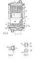
- the boiler comprises a casing 18 which is rectangular in plan and has, at its upper end, a water flow header or collector manifold 1 and, at its lower end, a water return header or collector manifold 2, these latter being interconnected by a number of finned water tubes 3 extending within the casing.
- the water tubes 3 account for the major proportion of heat transfer within the boiler and take the form of hollow tubes which together form the boiler water way.
- the exterior of each tube is finned as shown in detail in Figure 4, the fins extending longitudinally along the said tube.
- the walls of the casing 18 are fabricated as a sandwich of thermal insulating material between a pair of thin sheets of metal, for example steel.
- the finned tubes are made from aluminium alloy and are advantageously extruded to the required shape using a suitably cut die.
- the tubes 3 are arranged in abutting relationship in rows, as is seen clearly in Figure 2, and one such row of tubes is arranged against each of two opposite inside surfaces of the walls of the casing 18. As explained in more detail later, a gap 30 is left between the top of the tubes and the lower wall of the flow manifold 1 and between the bottom of the tubes and the upper wall of the return manifold 2.
- a platform 21 is situated in the central chamber and mounts a gas burner assembly 11 and gas input conduit 22.
- the platform 21 effectively splits the casing into two chambers: an upper, combustion chamber 6 and a lower, exhaust, chamber 23 from which a flue pipe 15 extends.
- Combustion products generated in the chamber 6 pass upwards through the chamber and past the inwardly-directed fins 17 on the rows of tubes 4 and thence through the gap 30 left at the top of the tubes into an " intermediate" zone 7 where the gases pass between the outwardly-directed fins 14 of the tubes 4.
- the fins may conveniently be of differing surface area to thickness ratios, as shown-in Figure 4.
- Such a longitudinally finned tube may be readily produced as an extruded metal section where the shape and dimensions of the section profile is determined by shapes cut into the die through which the metal is extruded. Aluminium alloys possess the qualities to satisfy both the requirements of high thermal conductivity and suitability for extrusion.
- the extruded section is so arranged that the waterway is formed as a circular tube within the extruded section at the periphery of which longitudinally extending fins are arranged with a surface to cross sectional area ratio to suit the heat exchange requirements of that particular part of the flow path of combustion products.
- a boiler of such construction may take the form of a variety of configurations where the extruded heat exchanger tubes may be arranged on one or more sides of the burner assembly 11 or may completely surround the burner assembly. All such configurations possess in common a combustion chamber 6 located within the confines of the space enclosed by the axially finned heat exchanger tubes and the water collector manifolds 1 and 2.
- each tube 4 is connected to the adjacent manifold 1/2 by means of a ferrule 10 of steel or hard anodised aluminium.
- ferrules are a press fit, preferably an interference fit, into the ends of the tubes and the walls of the manifolds respectively (which latter are suitably drilled for the purpose) so as to provide a mechanically stable and water-tight joint.
- the central part 24 of the ferrule is widened to define a pair of shoulders which act as abutment surfaces during assembly and ensure that a gap, corresponding to the length of the part 24 is left between the top and bottom of the tubes 4 and the adjacent manifold, as explained above.
- the action of the baffle 16 is to effectively force the combustion gases, which are now at diminished temperature, up through the inner fins 17 of the extruded heat exchanger tube which are in contact with the coldest water, being adjacent to the return water flow. It is in this region that condensation of the water vapour within the products of combustion occurs, being brought about by the return water being at a slightly lower temperature than the dew point of the flue gases at that point. This function raises the overall thermal efficiency by several percentage points.
- the surface area of the fins 17 in the condensation zone may be increased, after extrusion of the finned tube, by welding or otherwise affixing further fins between those already present. This will improve the heat transfer in this area.
- a boiler utilizing the features described above can be made very compact and lightweight for its thermal rating and the method of construction allows for ease of access for general service and maintenance. It could utilize burners or combustors of the forced convection type in common use.
- the above described construction has a particular advantage in manufacture as the whole compact assembly can be pressed together in a single operation eliminating the need for screwed connectors or gaskets or welds.
- Corrosion may be experienced when using aluminium tubes, particularly in the condensing zone 8, for this reason it might be advantageous to anodise the finned tubes on their exterior surfaces to minimise this problem.
Landscapes
- Engineering & Computer Science (AREA)
- Physics & Mathematics (AREA)
- Thermal Sciences (AREA)
- Chemical & Material Sciences (AREA)
- Combustion & Propulsion (AREA)
- Mechanical Engineering (AREA)
- General Engineering & Computer Science (AREA)
- Details Of Fluid Heaters (AREA)
- Heat-Exchange Devices With Radiators And Conduit Assemblies (AREA)
- Instantaneous Water Boilers, Portable Hot-Water Supply Apparatuses, And Control Of Portable Hot-Water Supply Apparatuses (AREA)
Applications Claiming Priority (2)
| Application Number | Priority Date | Filing Date | Title |
|---|---|---|---|
| GB838313803A GB8313803D0 (en) | 1983-05-18 | 1983-05-18 | Gas fired boilers |
| GB8313803 | 1983-05-18 |
Publications (1)
| Publication Number | Publication Date |
|---|---|
| EP0142214A1 true EP0142214A1 (fr) | 1985-05-22 |
Family
ID=10542993
Family Applications (1)
| Application Number | Title | Priority Date | Filing Date |
|---|---|---|---|
| EP84303411A Withdrawn EP0142214A1 (fr) | 1983-05-18 | 1984-05-18 | Chaudière de chauffage |
Country Status (3)
| Country | Link |
|---|---|
| EP (1) | EP0142214A1 (fr) |
| GB (1) | GB8313803D0 (fr) |
| WO (1) | WO1984004578A1 (fr) |
Cited By (6)
| Publication number | Priority date | Publication date | Assignee | Title |
|---|---|---|---|---|
| WO2014014340A1 (fr) * | 2012-06-14 | 2014-01-23 | Samsom Installaties B.V. | Dispositif et procédé permettant de chauffer un fluide tel que l'eau, chauffage et eau de robinet |
| US8709287B2 (en) | 2012-05-18 | 2014-04-29 | Air Products And Chemicals, Inc. | Water purification using energy from a steam-hydrocarbon reforming process |
| US8920771B2 (en) | 2012-05-18 | 2014-12-30 | Air Products And Chemicals, Inc. | Water purification using energy from a steam-hydrocarbon reforming process |
| US8920772B2 (en) | 2012-05-18 | 2014-12-30 | Air Products And Chemicals, Inc. | System and process for producing a H2-containing gas and purified water |
| US8956587B1 (en) | 2013-10-23 | 2015-02-17 | Air Products And Chemicals, Inc. | Hydrogen production process with high export steam |
| US9309130B2 (en) | 2013-10-23 | 2016-04-12 | Air Products And Chemicals, Inc. | Integrated process for the production of hydrogen and water |
Families Citing this family (1)
| Publication number | Priority date | Publication date | Assignee | Title |
|---|---|---|---|---|
| CN112460567B (zh) * | 2020-11-23 | 2021-12-28 | 西安交通大学 | 一种同心单管圈水冷燃烧及换热的燃气锅炉 |
Citations (6)
| Publication number | Priority date | Publication date | Assignee | Title |
|---|---|---|---|---|
| CH213398A (fr) * | 1937-10-23 | 1941-02-15 | Groll Charles | Chaudière verticale multitubulaire. |
| CH305827A (de) * | 1952-11-07 | 1955-03-15 | Tech Studien Ag | Erhitzer für Gase und Dämpfe. |
| DE2036012A1 (de) * | 1970-07-21 | 1972-01-27 | Reynolds, Spencer E., Murrysville, Pa. (V.St-A.) | Heizkörperabschnitt, insbesondere für Gasheizungen mit Wasser als Wärmeträger |
| EP0027055A1 (fr) * | 1979-10-09 | 1981-04-15 | Stelrad Group Limited | Chauffe-eau |
| EP0064755A2 (fr) * | 1981-05-09 | 1982-11-17 | Heinz-Dieter Seeger | Chaudière avec température basse des fumées |
| EP0067798A1 (fr) * | 1981-06-12 | 1982-12-22 | Antonino Candiano | Radiateur hydrothermique, constitué par éléments extrudés d'un alliage d'aluminium, joint par des raccords permanents |
-
1983
- 1983-05-18 GB GB838313803A patent/GB8313803D0/en active Pending
-
1984
- 1984-05-18 WO PCT/GB1984/000172 patent/WO1984004578A1/fr not_active Ceased
- 1984-05-18 EP EP84303411A patent/EP0142214A1/fr not_active Withdrawn
Patent Citations (6)
| Publication number | Priority date | Publication date | Assignee | Title |
|---|---|---|---|---|
| CH213398A (fr) * | 1937-10-23 | 1941-02-15 | Groll Charles | Chaudière verticale multitubulaire. |
| CH305827A (de) * | 1952-11-07 | 1955-03-15 | Tech Studien Ag | Erhitzer für Gase und Dämpfe. |
| DE2036012A1 (de) * | 1970-07-21 | 1972-01-27 | Reynolds, Spencer E., Murrysville, Pa. (V.St-A.) | Heizkörperabschnitt, insbesondere für Gasheizungen mit Wasser als Wärmeträger |
| EP0027055A1 (fr) * | 1979-10-09 | 1981-04-15 | Stelrad Group Limited | Chauffe-eau |
| EP0064755A2 (fr) * | 1981-05-09 | 1982-11-17 | Heinz-Dieter Seeger | Chaudière avec température basse des fumées |
| EP0067798A1 (fr) * | 1981-06-12 | 1982-12-22 | Antonino Candiano | Radiateur hydrothermique, constitué par éléments extrudés d'un alliage d'aluminium, joint par des raccords permanents |
Cited By (6)
| Publication number | Priority date | Publication date | Assignee | Title |
|---|---|---|---|---|
| US8709287B2 (en) | 2012-05-18 | 2014-04-29 | Air Products And Chemicals, Inc. | Water purification using energy from a steam-hydrocarbon reforming process |
| US8920771B2 (en) | 2012-05-18 | 2014-12-30 | Air Products And Chemicals, Inc. | Water purification using energy from a steam-hydrocarbon reforming process |
| US8920772B2 (en) | 2012-05-18 | 2014-12-30 | Air Products And Chemicals, Inc. | System and process for producing a H2-containing gas and purified water |
| WO2014014340A1 (fr) * | 2012-06-14 | 2014-01-23 | Samsom Installaties B.V. | Dispositif et procédé permettant de chauffer un fluide tel que l'eau, chauffage et eau de robinet |
| US8956587B1 (en) | 2013-10-23 | 2015-02-17 | Air Products And Chemicals, Inc. | Hydrogen production process with high export steam |
| US9309130B2 (en) | 2013-10-23 | 2016-04-12 | Air Products And Chemicals, Inc. | Integrated process for the production of hydrogen and water |
Also Published As
| Publication number | Publication date |
|---|---|
| WO1984004578A1 (fr) | 1984-11-22 |
| GB8313803D0 (en) | 1983-06-22 |
Similar Documents
| Publication | Publication Date | Title |
|---|---|---|
| EP0414433B1 (fr) | Duplex échangeur de chaleur | |
| US5238057A (en) | Finned-tube heat exchanger | |
| PL178916B1 (pl) | Rura wymiennika ciepła do kotła grzejnego | |
| EP0085470B1 (fr) | Chaudière à condensation | |
| CA1211016A (fr) | Chaudiere compacte haute performance | |
| KR100414852B1 (ko) | 열교환기용냉매유통관 | |
| WO1984004578A1 (fr) | Ameliorations en matiere de chaudieres de chauffage | |
| GB2140138A (en) | Heating boilers | |
| US5915468A (en) | High-temperature generator | |
| GB2073395A (en) | A heat exchanger for cooling a high temperature fluid | |
| RU2146790C1 (ru) | Водогрейный водотрубный котел | |
| JPH0755380A (ja) | 熱交換器 | |
| EP0133039A1 (fr) | Chaudière pour chauffage | |
| RU2132023C1 (ru) | Водогрейный котел | |
| CN215765001U (zh) | 一种采用新型换热方式的锅壳式燃油燃气水管锅炉 | |
| GB2103351A (en) | Flue arrangements for boilers | |
| CA1171332A (fr) | Appareil chauffant | |
| US4410037A (en) | Recuperator | |
| RU2158394C1 (ru) | Отопительный котел | |
| PL191986B1 (pl) | Element wymiennika ciepła | |
| RU2826915C1 (ru) | Двухкамерный мультитеплотрубный теплообменник | |
| US6763786B2 (en) | Equipment for water heater | |
| RU2266491C1 (ru) | Способ изготовления теплообменной секции аппарата воздушного охлаждения газа и теплообменная секция аппарата воздушного охлаждения газа | |
| RU2057997C1 (ru) | Горизонтально-водотрубный котел | |
| KR840001256Y1 (ko) | 온수 보일러 |
Legal Events
| Date | Code | Title | Description |
|---|---|---|---|
| PUAI | Public reference made under article 153(3) epc to a published international application that has entered the european phase |
Free format text: ORIGINAL CODE: 0009012 |
|
| AK | Designated contracting states |
Designated state(s): DE FR GB IT NL SE |
|
| 17P | Request for examination filed |
Effective date: 19851114 |
|
| 17Q | First examination report despatched |
Effective date: 19860407 |
|
| STAA | Information on the status of an ep patent application or granted ep patent |
Free format text: STATUS: THE APPLICATION IS DEEMED TO BE WITHDRAWN |
|
| 18D | Application deemed to be withdrawn |
Effective date: 19860818 |
|
| RIN1 | Information on inventor provided before grant (corrected) |
Inventor name: SIMPSON, VICTOR JOHN |