EP0142260A1 - Rasensprenger - Google Patents
Rasensprenger Download PDFInfo
- Publication number
- EP0142260A1 EP0142260A1 EP84306886A EP84306886A EP0142260A1 EP 0142260 A1 EP0142260 A1 EP 0142260A1 EP 84306886 A EP84306886 A EP 84306886A EP 84306886 A EP84306886 A EP 84306886A EP 0142260 A1 EP0142260 A1 EP 0142260A1
- Authority
- EP
- European Patent Office
- Prior art keywords
- water
- curved surface
- dispersing member
- lawn sprinkler
- spindle
- Prior art date
- Legal status (The legal status is an assumption and is not a legal conclusion. Google has not performed a legal analysis and makes no representation as to the accuracy of the status listed.)
- Granted
Links
Images


Classifications
-
- B—PERFORMING OPERATIONS; TRANSPORTING
- B05—SPRAYING OR ATOMISING IN GENERAL; APPLYING FLUENT MATERIALS TO SURFACES, IN GENERAL
- B05B—SPRAYING APPARATUS; ATOMISING APPARATUS; NOZZLES
- B05B3/00—Spraying or sprinkling apparatus with moving outlet elements or moving deflecting elements
- B05B3/02—Spraying or sprinkling apparatus with moving outlet elements or moving deflecting elements with rotating elements
- B05B3/04—Spraying or sprinkling apparatus with moving outlet elements or moving deflecting elements with rotating elements driven by the liquid or other fluent material discharged, e.g. the liquid actuating a motor before passing to the outlet
- B05B3/0417—Spraying or sprinkling apparatus with moving outlet elements or moving deflecting elements with rotating elements driven by the liquid or other fluent material discharged, e.g. the liquid actuating a motor before passing to the outlet comprising a liquid driven rotor, e.g. a turbine
- B05B3/0425—Spraying or sprinkling apparatus with moving outlet elements or moving deflecting elements with rotating elements driven by the liquid or other fluent material discharged, e.g. the liquid actuating a motor before passing to the outlet comprising a liquid driven rotor, e.g. a turbine actuated downstream of the outlet elements
- B05B3/0426—Spraying or sprinkling apparatus with moving outlet elements or moving deflecting elements with rotating elements driven by the liquid or other fluent material discharged, e.g. the liquid actuating a motor before passing to the outlet comprising a liquid driven rotor, e.g. a turbine actuated downstream of the outlet elements the liquid driven rotor being a deflecting rotating element
Definitions
- the invention aims to provide a lawn sprinkler which is simple and reliable in operation, has fewer moving parts than known sprinklers and provides good_ distribution of spray, particularly in the area close to the sprinkler.
- a lawn sprinkler comprising a water dispersing member mounted for free rotation about a vertical axis, and a nozzle which is arranged to direct a water jet upwardly, in a direction parallel to said axis of rotation of the dispersing member, onto a first, convexly curved surface of the dispersing member, the latter surface being arranged to distribute the water from the jet onto a second, concavely curved surface of the dispersing member which is configured and positioned such that the water impinging thereon is dispersed from the concavely curved surface through a substantial range of angles of elevation, the reaction to the force of water impinging on the dispersing member being arranged to cause rotation of the dispersing member about said axis, so that the water flung off the dispersing member is distributed through 360 about said axis of rotation.
- the dispersing member is shaped so that water is dispersed therefrom through a range of angles of elevation extending from substantially vertically downwardly to substantially horizontal.
- the convexly curved surface has a radius of curvature perpendicular to the radius of curvature of the concavely curved surface.
- the convexly curved surface is part-cylindrical, the corresponding notional cylinder having a substantially horizontal central axis, and the concavely curved surface is also part-cylindrical, the corresponding notional cylinder having a substantially horizontal central axis orthogonal to the central axis of the cylinder forming part of the convexly curved surface.
- the convexly curved surface and the concavely curved surface may be adjacent on the water dispersing member and may adjoin along a line of transition.
- the dispersing member is preferably pivotally mounted on a spindle which extends upwardly through said nozzle, with an annular clearance between the spindle and the nozzle for the passage of water.
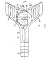
- rhe lawn sprinkler has a base 10 which is generally Y-shaped in plan, as viewed in Figure 1. To one limb 12 of the base 10 is attached a hose connector 14, providing for attachment to a flexible hose (not shown). The two remaining limbs 16, 18 of the base 10 extend outwardly in a splayed manner to afford stability of the sprinkler which rests on the ground at four locations 20, 22, 24, 26 disposed on the undersides of the limbs 12, 16, 18.
- a water dispersing member 28 is mounted on the base 10 about a vertical pivot axis 30.
- the base 10 has a moulded body 32 having a water passage 34 which leads from the hose connector 14, through the core of the limb 12 to a circular aperture 36 centred on the axis 30.
- the aperture 36 leads to a circular recess 38 into which fits a boss-like projection 40 formed on the underside of a cover 42, visible also in Figures 1 to 3.
- the internal wall of the boss-like projection 40 has four equi-angularly disposed slots 44, and the slots receive four fins 45 formed on a spindle 46.
- the spindle extends upwardly, with all round radial clearance with respect to a , circular aperture 50 in the cover 42, and the water dispersing member 28 is pivotally mounted on the projecting upper end of the spindle 46 which is retained in position and held against rotation by the location of the fins 45 in the slots 44.
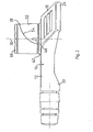
- the water dispersing member 28 has a convexly part-cylindrical surface 52 adjoining a concavely curved part-cylindrical surface 54.
- the position of the surface 52 is best shown in Figure 3, and the position of the surface 54 is best shown in Figure 2.
- the two surfaces 52 and 54 have radii lying in orthogonal planes and meet along a complexly curved line.
- the water dispersing member 28 has a part-cylindrical outer wall and a recess bounded by the surfaces 52 and 54 and also has a projection 58 (best seen in Figure 1) overlying the upper region of the concave surface 54.
- the water dispersing member 28 is moulded from a plastics material so as to be hollow, the member 28 being covered by a separately moulded cap 60 secured (eg by sonic welding) on the top of the member 28.
- the member 28 is moulded with a cylindrical bearing sleeve 62 ( Figure 4) by which the member 28 is pivotally mounted on the spindle 46.
- a circlip or the like (not shown) locates in a groove 48 at the upper end of the spindle 46 to prevent the member 28 being lifted off the spindle which is fixed in the base 10 by virtue of the cover 42 being sonically welded to the moulded body 32.
- water supplied by the hose pipe passes through the hose connector 14 and water passage 34 to reach the chamber defined within the boss-like projection 40. From this chamber, the water issues as a jet from the nozzle defined by the annular clearance gap between the aperture 50 and the spindle 46.
- the upwardly directed stream of water issuing from the nozzle impinges upon the convex surface 52, whence it is deflected onto the concave surface ' 54. The result is that the water streams off the outer edge of the concave surface, water droplets of comparatively low velocity leaving the lower part of the edge and the water droplets of higher velocity leaving the higher part of the edge.
- Each of the curved surfaces 52 and 54 extends through an arc of approximately 90 , and water leaves the edge of the concave surface through a range of angles of elevation between vertically downwards (at the lower part of the edge) and horizontal (at the upper part of the edge).
- the dispersing member 28 is shaped so as to be dynamically balanced and prevent vibration. To achieve this, the y dispersing member 28 has a weighted or solid portion the position of which is indicated at 64 in Figure 1.
Landscapes
- Nozzles (AREA)
- Catching Or Destruction (AREA)
Priority Applications (1)
| Application Number | Priority Date | Filing Date | Title |
|---|---|---|---|
| AT84306886T ATE28278T1 (de) | 1983-10-13 | 1984-10-09 | Rasensprenger. |
Applications Claiming Priority (4)
| Application Number | Priority Date | Filing Date | Title |
|---|---|---|---|
| GB838327423A GB8327423D0 (en) | 1983-10-13 | 1983-10-13 | Lawn sprinkler |
| GB8327423 | 1983-10-13 | ||
| GB838331049A GB8331049D0 (en) | 1983-10-13 | 1983-11-21 | Lawn sprinkler |
| GB8331049 | 1983-11-21 |
Publications (2)
| Publication Number | Publication Date |
|---|---|
| EP0142260A1 true EP0142260A1 (de) | 1985-05-22 |
| EP0142260B1 EP0142260B1 (de) | 1987-07-15 |
Family
ID=26286917
Family Applications (1)
| Application Number | Title | Priority Date | Filing Date |
|---|---|---|---|
| EP84306886A Expired EP0142260B1 (de) | 1983-10-13 | 1984-10-09 | Rasensprenger |
Country Status (3)
| Country | Link |
|---|---|
| US (1) | US4597528A (de) |
| EP (1) | EP0142260B1 (de) |
| DE (1) | DE3464700D1 (de) |
Cited By (3)
| Publication number | Priority date | Publication date | Assignee | Title |
|---|---|---|---|---|
| US7090146B1 (en) | 2004-03-23 | 2006-08-15 | Orbit Irrigation Products, Inc. | Above-ground adjustable spray pattern sprinkler |
| KR101239019B1 (ko) * | 2006-06-09 | 2013-03-04 | 애플 인크. | 터치 스크린 액정 디스플레이 |
| US11086444B2 (en) | 2013-12-13 | 2021-08-10 | Apple Inc. | Integrated touch and display architectures for self-capacitive touch sensors |
Families Citing this family (6)
| Publication number | Priority date | Publication date | Assignee | Title |
|---|---|---|---|---|
| USD313269S (en) | 1987-07-23 | 1990-12-25 | Gardena Kress & Kastner Gmbh | Sprinkler |
| USD315014S (en) | 1988-02-10 | 1991-02-26 | Gardena Kress & Kastner Gmbh | Sprayer |
| ES2061344B1 (es) * | 1991-08-20 | 1995-06-01 | Zvi Rubenstein | Aspersor rotativo. |
| US6189622B1 (en) | 1999-05-11 | 2001-02-20 | Le Group-Conseil Lasalle, Inc. | Nozzle for fighting fires in buildings |
| US9775306B2 (en) | 2015-04-14 | 2017-10-03 | Yuan-Mei Corp. | Above ground sprinkler |
| US10322421B2 (en) | 2015-04-14 | 2019-06-18 | Yuan-Mei Corp. | Sprinkler |
Citations (3)
| Publication number | Priority date | Publication date | Assignee | Title |
|---|---|---|---|---|
| US1831540A (en) * | 1930-03-20 | 1931-11-10 | Lewen R Nelson | Lawn sprinkler |
| AT167364B (de) * | 1948-07-23 | 1950-12-27 | Karl Georg Wanke | Regner zur Beregnung von Flächen geringen Ausmaßes |
| EP0010925A1 (de) * | 1978-10-30 | 1980-05-14 | Irritech, Advanced Irrigation Technologies | Spritz- oder Zerstäuberdüse |
Family Cites Families (3)
| Publication number | Priority date | Publication date | Assignee | Title |
|---|---|---|---|---|
| US1467601A (en) * | 1921-09-03 | 1923-09-11 | Edward C Chambers | Sprinkler |
| US1481327A (en) * | 1922-11-04 | 1924-01-22 | Herbert E Merseles | Method and apparatus for distributing liquids |
| US2634163A (en) * | 1948-02-20 | 1953-04-07 | Glenn O Double | Sprinkler head assembly |
-
1984
- 1984-10-09 DE DE8484306886T patent/DE3464700D1/de not_active Expired
- 1984-10-09 EP EP84306886A patent/EP0142260B1/de not_active Expired
- 1984-10-10 US US06/659,422 patent/US4597528A/en not_active Expired - Fee Related
Patent Citations (3)
| Publication number | Priority date | Publication date | Assignee | Title |
|---|---|---|---|---|
| US1831540A (en) * | 1930-03-20 | 1931-11-10 | Lewen R Nelson | Lawn sprinkler |
| AT167364B (de) * | 1948-07-23 | 1950-12-27 | Karl Georg Wanke | Regner zur Beregnung von Flächen geringen Ausmaßes |
| EP0010925A1 (de) * | 1978-10-30 | 1980-05-14 | Irritech, Advanced Irrigation Technologies | Spritz- oder Zerstäuberdüse |
Cited By (4)
| Publication number | Priority date | Publication date | Assignee | Title |
|---|---|---|---|---|
| US7090146B1 (en) | 2004-03-23 | 2006-08-15 | Orbit Irrigation Products, Inc. | Above-ground adjustable spray pattern sprinkler |
| KR101239019B1 (ko) * | 2006-06-09 | 2013-03-04 | 애플 인크. | 터치 스크린 액정 디스플레이 |
| KR101239030B1 (ko) * | 2006-06-09 | 2013-03-04 | 애플 인크. | 터치 스크린 액정 디스플레이 |
| US11086444B2 (en) | 2013-12-13 | 2021-08-10 | Apple Inc. | Integrated touch and display architectures for self-capacitive touch sensors |
Also Published As
| Publication number | Publication date |
|---|---|
| DE3464700D1 (en) | 1987-08-20 |
| EP0142260B1 (de) | 1987-07-15 |
| US4597528A (en) | 1986-07-01 |
Similar Documents
| Publication | Publication Date | Title |
|---|---|---|
| EP0761312B1 (de) | Kunststoff-Sprühdüse mit verbesserter Abgabe | |
| EP0723814B1 (de) | Vorrichtung mit einer ozillierten Brause | |
| AU721238B2 (en) | Nutating sprinkler with rotary shaft and seal | |
| US5307993A (en) | Rotary sprinkler | |
| US5971297A (en) | Sprinkler with nozzle venturi | |
| US4783004A (en) | Ball drive sprinkler | |
| US4026471A (en) | Sprinkler systems | |
| US4597528A (en) | Lawn sprinkler | |
| US6736332B2 (en) | Adjustable arc, adjustable flow rate sprinkler | |
| US3832069A (en) | Cleaning apparatus | |
| US20060273202A1 (en) | Adjustable lawn sprinkler | |
| US3829019A (en) | Spinner assembly | |
| US20040046047A1 (en) | Reversible adjustable arc sprinkler | |
| EP0136349A1 (de) | Flusskontrolldüse | |
| EP3613510B1 (de) | Duschkopf | |
| EP0601822A1 (de) | Sprühdüse mit einem vertieften Deflektor | |
| EP0518666B1 (de) | Sprühdüsen | |
| EP0776702A3 (de) | Rotierender Regner mit einem Revolver-Kopf | |
| EP0130135B1 (de) | Flüssigkeitszerstäubungsgerät | |
| US4474328A (en) | Variable lift sprinkler unit | |
| US5232157A (en) | Insect resistant spray emitter | |
| JPS6323761A (ja) | 制御されたパタ−ンで揺動するスプリンクラ− | |
| JPH0724793B2 (ja) | 散水装置 | |
| US4512519A (en) | Sprinkler | |
| US4735361A (en) | Jet deflecting sprinkler head |
Legal Events
| Date | Code | Title | Description |
|---|---|---|---|
| PUAI | Public reference made under article 153(3) epc to a published international application that has entered the european phase |
Free format text: ORIGINAL CODE: 0009012 |
|
| AK | Designated contracting states |
Designated state(s): AT BE CH DE FR GB IT LI LU NL SE |
|
| 17P | Request for examination filed |
Effective date: 19850412 |
|
| 17Q | First examination report despatched |
Effective date: 19860203 |
|
| ITF | It: translation for a ep patent filed | ||
| GRAA | (expected) grant |
Free format text: ORIGINAL CODE: 0009210 |
|
| AK | Designated contracting states |
Kind code of ref document: B1 Designated state(s): AT BE CH DE FR GB IT LI LU NL SE |
|
| PG25 | Lapsed in a contracting state [announced via postgrant information from national office to epo] |
Ref country code: NL Effective date: 19870715 Ref country code: LI Effective date: 19870715 Ref country code: CH Effective date: 19870715 Ref country code: BE Effective date: 19870715 Ref country code: AT Effective date: 19870715 |
|
| REF | Corresponds to: |
Ref document number: 28278 Country of ref document: AT Date of ref document: 19870815 Kind code of ref document: T |
|
| PG25 | Lapsed in a contracting state [announced via postgrant information from national office to epo] |
Ref country code: SE Effective date: 19870731 |
|
| REF | Corresponds to: |
Ref document number: 3464700 Country of ref document: DE Date of ref document: 19870820 |
|
| ET | Fr: translation filed | ||
| REG | Reference to a national code |
Ref country code: CH Ref legal event code: PL |
|
| PG25 | Lapsed in a contracting state [announced via postgrant information from national office to epo] |
Ref country code: LU Free format text: LAPSE BECAUSE OF NON-PAYMENT OF DUE FEES Effective date: 19871031 |
|
| NLV1 | Nl: lapsed or annulled due to failure to fulfill the requirements of art. 29p and 29m of the patents act | ||
| PLBE | No opposition filed within time limit |
Free format text: ORIGINAL CODE: 0009261 |
|
| STAA | Information on the status of an ep patent application or granted ep patent |
Free format text: STATUS: NO OPPOSITION FILED WITHIN TIME LIMIT |
|
| 26N | No opposition filed | ||
| PGFP | Annual fee paid to national office [announced via postgrant information from national office to epo] |
Ref country code: DE Payment date: 19890726 Year of fee payment: 6 |
|
| PGFP | Annual fee paid to national office [announced via postgrant information from national office to epo] |
Ref country code: GB Payment date: 19890731 Year of fee payment: 6 |
|
| PGFP | Annual fee paid to national office [announced via postgrant information from national office to epo] |
Ref country code: FR Payment date: 19890823 Year of fee payment: 6 |
|
| ITTA | It: last paid annual fee | ||
| PG25 | Lapsed in a contracting state [announced via postgrant information from national office to epo] |
Ref country code: GB Effective date: 19901009 |
|
| GBPC | Gb: european patent ceased through non-payment of renewal fee | ||
| PG25 | Lapsed in a contracting state [announced via postgrant information from national office to epo] |
Ref country code: FR Effective date: 19910628 |
|
| PG25 | Lapsed in a contracting state [announced via postgrant information from national office to epo] |
Ref country code: DE Effective date: 19910702 |
|
| REG | Reference to a national code |
Ref country code: FR Ref legal event code: ST |