EP0142284B1 - Rayon moulé d'une seule pièce et moule à injection pour sa fabrication - Google Patents
Rayon moulé d'une seule pièce et moule à injection pour sa fabrication Download PDFInfo
- Publication number
- EP0142284B1 EP0142284B1 EP84307121A EP84307121A EP0142284B1 EP 0142284 B1 EP0142284 B1 EP 0142284B1 EP 84307121 A EP84307121 A EP 84307121A EP 84307121 A EP84307121 A EP 84307121A EP 0142284 B1 EP0142284 B1 EP 0142284B1
- Authority
- EP
- European Patent Office
- Prior art keywords
- tier
- mould
- edges
- bars
- rack
- Prior art date
- Legal status (The legal status is an assumption and is not a legal conclusion. Google has not performed a legal analysis and makes no representation as to the accuracy of the status listed.)
- Expired
Links
- 238000004519 manufacturing process Methods 0.000 title claims description 5
- 238000002347 injection Methods 0.000 claims description 27
- 239000007924 injection Substances 0.000 claims description 27
- 125000006850 spacer group Chemical group 0.000 claims description 21
- 230000002093 peripheral effect Effects 0.000 claims description 5
- 230000000717 retained effect Effects 0.000 claims 1
- 238000012360 testing method Methods 0.000 description 39
- 230000000875 corresponding effect Effects 0.000 description 16
- 239000004033 plastic Substances 0.000 description 15
- 229920003023 plastic Polymers 0.000 description 15
- 239000000463 material Substances 0.000 description 12
- 230000015572 biosynthetic process Effects 0.000 description 8
- 238000013461 design Methods 0.000 description 6
- 238000010276 construction Methods 0.000 description 5
- 238000001746 injection moulding Methods 0.000 description 5
- 229910052751 metal Inorganic materials 0.000 description 5
- 239000002184 metal Substances 0.000 description 5
- 238000012986 modification Methods 0.000 description 5
- 230000004048 modification Effects 0.000 description 5
- 238000000926 separation method Methods 0.000 description 5
- 238000000034 method Methods 0.000 description 4
- -1 for example Substances 0.000 description 3
- 230000013011 mating Effects 0.000 description 3
- 229910000831 Steel Inorganic materials 0.000 description 2
- GWEVSGVZZGPLCZ-UHFFFAOYSA-N Titan oxide Chemical compound O=[Ti]=O GWEVSGVZZGPLCZ-UHFFFAOYSA-N 0.000 description 2
- 230000002079 cooperative effect Effects 0.000 description 2
- 238000005260 corrosion Methods 0.000 description 2
- 230000007797 corrosion Effects 0.000 description 2
- 239000003365 glass fiber Substances 0.000 description 2
- 231100001261 hazardous Toxicity 0.000 description 2
- VYPSYNLAJGMNEJ-UHFFFAOYSA-N silicon dioxide Inorganic materials O=[Si]=O VYPSYNLAJGMNEJ-UHFFFAOYSA-N 0.000 description 2
- 239000007787 solid Substances 0.000 description 2
- 239000010959 steel Substances 0.000 description 2
- 238000003466 welding Methods 0.000 description 2
- ZOXJGFHDIHLPTG-UHFFFAOYSA-N Boron Chemical compound [B] ZOXJGFHDIHLPTG-UHFFFAOYSA-N 0.000 description 1
- OKTJSMMVPCPJKN-UHFFFAOYSA-N Carbon Chemical compound [C] OKTJSMMVPCPJKN-UHFFFAOYSA-N 0.000 description 1
- 239000004952 Polyamide Substances 0.000 description 1
- 239000004698 Polyethylene Substances 0.000 description 1
- 239000004743 Polypropylene Substances 0.000 description 1
- 239000004793 Polystyrene Substances 0.000 description 1
- 238000013459 approach Methods 0.000 description 1
- 238000003491 array Methods 0.000 description 1
- 229910052796 boron Inorganic materials 0.000 description 1
- 229910052799 carbon Inorganic materials 0.000 description 1
- 239000006229 carbon black Substances 0.000 description 1
- 238000006243 chemical reaction Methods 0.000 description 1
- 238000007705 chemical test Methods 0.000 description 1
- 239000011248 coating agent Substances 0.000 description 1
- 238000000576 coating method Methods 0.000 description 1
- 238000001816 cooling Methods 0.000 description 1
- 230000003028 elevating effect Effects 0.000 description 1
- 239000000945 filler Substances 0.000 description 1
- 239000000383 hazardous chemical Substances 0.000 description 1
- 229920005669 high impact polystyrene Polymers 0.000 description 1
- 239000004797 high-impact polystyrene Substances 0.000 description 1
- 238000007689 inspection Methods 0.000 description 1
- JEIPFZHSYJVQDO-UHFFFAOYSA-N iron(III) oxide Inorganic materials O=[Fe]O[Fe]=O JEIPFZHSYJVQDO-UHFFFAOYSA-N 0.000 description 1
- 238000002372 labelling Methods 0.000 description 1
- 239000007788 liquid Substances 0.000 description 1
- 239000011159 matrix material Substances 0.000 description 1
- 238000003801 milling Methods 0.000 description 1
- 238000000465 moulding Methods 0.000 description 1
- 238000004806 packaging method and process Methods 0.000 description 1
- 238000012856 packing Methods 0.000 description 1
- 229920002647 polyamide Polymers 0.000 description 1
- 239000004417 polycarbonate Substances 0.000 description 1
- 229920000515 polycarbonate Polymers 0.000 description 1
- 229920000573 polyethylene Polymers 0.000 description 1
- 229920006324 polyoxymethylene Polymers 0.000 description 1
- 229920001155 polypropylene Polymers 0.000 description 1
- 229920002223 polystyrene Polymers 0.000 description 1
- 229920002635 polyurethane Polymers 0.000 description 1
- 239000004814 polyurethane Substances 0.000 description 1
- 230000000750 progressive effect Effects 0.000 description 1
- 239000000377 silicon dioxide Substances 0.000 description 1
- 238000003860 storage Methods 0.000 description 1
- 238000005728 strengthening Methods 0.000 description 1
- 239000000126 substance Substances 0.000 description 1
- 239000004408 titanium dioxide Substances 0.000 description 1
Images




Classifications
-
- B—PERFORMING OPERATIONS; TRANSPORTING
- B01—PHYSICAL OR CHEMICAL PROCESSES OR APPARATUS IN GENERAL
- B01L—CHEMICAL OR PHYSICAL LABORATORY APPARATUS FOR GENERAL USE
- B01L9/00—Supporting devices; Holding devices
- B01L9/06—Test-tube stands; Test-tube holders
-
- B—PERFORMING OPERATIONS; TRANSPORTING
- B29—WORKING OF PLASTICS; WORKING OF SUBSTANCES IN A PLASTIC STATE IN GENERAL
- B29C—SHAPING OR JOINING OF PLASTICS; SHAPING OF MATERIAL IN A PLASTIC STATE, NOT OTHERWISE PROVIDED FOR; AFTER-TREATMENT OF THE SHAPED PRODUCTS, e.g. REPAIRING
- B29C45/00—Injection moulding, i.e. forcing the required volume of moulding material through a nozzle into a closed mould; Apparatus therefor
- B29C45/17—Component parts, details or accessories; Auxiliary operations
- B29C45/26—Moulds
- B29C45/33—Moulds having transversely, e.g. radially, movable mould parts
-
- B—PERFORMING OPERATIONS; TRANSPORTING
- B29—WORKING OF PLASTICS; WORKING OF SUBSTANCES IN A PLASTIC STATE IN GENERAL
- B29C—SHAPING OR JOINING OF PLASTICS; SHAPING OF MATERIAL IN A PLASTIC STATE, NOT OTHERWISE PROVIDED FOR; AFTER-TREATMENT OF THE SHAPED PRODUCTS, e.g. REPAIRING
- B29C45/00—Injection moulding, i.e. forcing the required volume of moulding material through a nozzle into a closed mould; Apparatus therefor
- B29C45/17—Component parts, details or accessories; Auxiliary operations
- B29C45/26—Moulds
- B29C45/33—Moulds having transversely, e.g. radially, movable mould parts
- B29C2045/338—Mould parts with combined axial and transversal movements
Definitions
- the present invention relates generally to a single-piece injection moulded rack and to the mould for producing it.
- the invention is advantageously employed to provide a plastics material test tube rack for medical and laboratory use.
- Test tube racks are widely used where it is desirable to perform biological or chemical tests in a related sequence or on a related group of specimens. Before performing such tests, it is frequently necessary to sterilize the test tubes and rack simultaneously. Many operations, as well, require the rack, the test tubes and their contents to be placed in an incubator to facilitate a chemical reaction or the growth of organisms within the medium under test. Often, autoclaves or incubators available in a particular laboratory have limited internal space, making it highly desirable to have a rack which will hold a dense array of test tubes.
- test tubes are more tightly grouped, however, it becomes increasingly necessary for the individual tubes to be maintained in proper alignment, so that material may be introduced or withdrawn from the tubes in an orderly sequential manner. In addition, the contents of the tubes must remain readily observable by the technician.
- the conventional wire rack is extensively employed in an effort to achieve these goals.
- racks are three-tiered structures, the individual tiers being rectangular grids formed by welding together individual metal rods.
- the tiers are then operatively joined by welding additional metal rods to each tier, vertically from top to bottom.
- the completed assembly is thereafter coated with a thin layer of conforming plastics material to protect the metal against corrosion and chemical attack.
- the plastics coating wears off, leading to rust and corrosion which render the racks unusable.
- wire racks function satisfactorily, they are costly to produce and, because of their weight, costly to ship in quantity. These costs are shared by the end user, making wire racks economically unsuitable for use as a disposable item of laboratory equipment. These racks, thus, are ill-suited for analytical operations in which the hazardous substances used dictate disposal of both test tubes and racks.
- test tubes made of plastics materials are commercially attractive.
- plastics test tube racks have been proposed, none has achieved the dense packing and tube visibility advantages of the wire rack.
- the usual approach, with such plastics racks has been to provide multiple plastics plates, each of the plates having a plurality of apertures for receiving the test tubes.
- the apertures are circular, to conform to the shape of the test tubes.
- the plates are separately moulded and thereafter assembled, using other separately moulded components. Since these single plates are relatively thin, they are easily formed by a simple mould section having projecting circular cores which cooperatively mate against a planar mould half.
- this type of plastics test tube rack requires assembly, thus yielding up some of the cost benefits associated with plastics manufacture. It would be most desirable if a plastics test tube rack could be manufactured as a single piece in a fully automated mould. It would be particularly advantageous if such a rack could also provide the dense two-dimensional test tube arrays and high visibility afforded by wire racks.
- the present invention achieves the objectives of equalling the test tube density and viewability advantages of the wire rack.
- the present invention significantly reduces the manufacturing cost associated with assembling a wire rack from individual metal rods as described above.
- the present invention provides a rack which can be offered more economically to the end user. Since the unique configurations of both the rack and the mould are suitable for a wide variety of plastics materials, racks can be produced which have functional characteristics ranging from durability and reusability to single- use disposability.
- a multitier rack for holding an array of test tubes or similar articles.
- the unique construction of the rack and, in particular, the configuration of the intermediate tier permits close spacing of the apertures, which at the same time minimizing the required thickness of the walls between apertures.
- An overall airy appearance results, greatly facilitating viewing of the contents of test tubes held by the rack. While the invention will be described throughout with respect to a three-tiered rack, from the ensuing description it will become apparent to those skilled in the art that more than one intermediate tier may be included in the structure.
- a single-piece injection-moulded rack is characterised by comprising: a plurality of spaced single-piece injection moulded rack characterised by: a plurality of spaced superposed tiers including a top tier, a bottom tier and an intermediate tier the intermediate tier being disposed between the top and bottom tiers, the top tier including apertures, the intermediate tier having a top set of bars and a bottom set of bars, bars within the top set being superposed over and intersecting bars within the bottom set to define apertures, apertures in the intermediate tier being aligned with apertures in the top tier;
- first support means for interconnecting the top tier and the intermediate tier
- second support means for interconnecting the intermediate tier and the bottom tier.
- the intermediate tier is a lattice having apertures defined by the intersection of two sets of bars.
- set is meant to encompass a group of bars and an assemblage of groups of bars.
- a top set of substantially parallel bars is superposed over a bottom set of substantially parallel bars, at right-angles, to define generally rectangular apertures.
- substantially parallel means that the longitudinal axis of a bar is aligned parallel to the longitudinal axis of another bar (or to the longitudinal axes of other bars) or is parallel to some other reference axis or plane. This preferred configuration enables formation of the intermediate tier with as few as two mould segments.
- each set of bars is formed by a slide which has parallel channels milled into a substantially planar surface.
- the two channel-containing surfaces are moved into and out of face-to-face engagement with each other along separate single axial paths which are oriented relative to one another in accordance with the desired angle of intersection of the two sets of bars.
- the axial path of movement of the slide forming the bottom set of bars is perpendicular to the axial path of movement of the slide forming the top set of bars. Since all of the channel-containing surfaces are substantially planar, when the mould is closed, the respective surfaces mate perfectly in the regions corresponding to the apertures in the lattice.
- the bars on the facing surfaces of adjacent intermediate tiers are parallel to one another and, in turn, parallel to the facing bars on the adjacent tier.
- the top bars on a given intermediate tier are parallel to the bottom bars on the intermediate tier immediately above it, while the bottom bars thereof are parallel to the top bars on the intermediate tier immediately below it.
- an injection mould for the manufacture of a single-piece rack having top, bottom and intermediate tiers selectively interconnected in spaced superposed relation, the intermediate tier being a lattice defined by intersecting top and bottom sets of bars, the bars within each set being substantially parallel and the top set of bars being superposed over the bottom set of bars, characterised by comprising and injection mould half and an ejection mould half, the ejection mould half being movable along a predetermined axial path relative to the injection mould half between a mould-closed position and a mould-open position and the ejection mould half cooperating with the injection mould half in the mould-closed position to define a mould cavity corresponding to the rack, wherein a first slide is associated with the injection mould half and has a lower surface portion having parallel channels corresponding in dimensions to the dimensions of the top set of bars of the intermediate tier and being aligned parallel to the axial path of movement of the ejection mould half; and wherein the ejection mould half includes a first core slide
- each set of bars is formed by a pair of cooperating slides which are movable along coaxial paths in opposed directions relative to one another.
- Each bar is formed by a pair of channels (one channel being provided on each of the opposed slides), which made end-to-end when the mould is closed. In similar fashion to the single slide arrangement, the pairs of channels are aligned parallel to the axial path of movement of the opposed slides.
- the slides are withdrawn in opposed directions away from one another and away from the moulded rack, along their coaxial paths, with the channels sliding over the portions of the bars they formed.
- This arrangement of cooperating pairs of slides advantageously permits the formation of supports between the top and intermediate tiers and between the bottom and intermediate tiers. This is accomplished by providing channels in the mating faces of the cooperating slides. By selecting unequal lengths for the slides within a pair, the supports may be positioned where desired between the facing surfaces of the tiers. As well, by selecting the number and configuration of channels in the mating faces of the slides, a plurality of supports may be formed.
- the bars within each of the sets are parallel.
- the bars within a particular group may be parallel to one another but not necessarily parallel to the bars within another group of the set.
- the supports which join the tiers together do not extend the full vertical span from top to intermediate to bottom tier.
- the top tier is interconnected with the intermediate tier and, in turn, the intermediate tier is separately connected at another place to the bottom tier.
- the top and intermediate tiers are connected at their extreme side edges by side supports whose facing inner surfaces are substantially planar and parallel to one another. With this configuration, the side supports are readily formed by side surfaces of the mould slides which form the top set of parallel bars.
- the supports connecting the intermediate tier to the bottom tier have substantially planar parallel inner surfaces.
- the supports between the intermediate and bottom tiers are formed by front and back side surfaces of the slides which form the bottom set of bars.
- the side supports and the front and back supports have surfaces lying in planes which are also perpendicular to one another. This arrangement not only simplifies mould design and enhances the rigidity of the rack, but also aids observation of the test tube contents from different directions.
- FIGURE 1 diagrammatically illustrates the relationship and relative movement among the mould segments which cooperate in the closed position to form a mould cavity corresponding to the rack 10 shown. This cooperative action can be appreciated more fully with a better understanding of the configuration of the preferred rack illustrated in FIGURE 2 and in greater detail in FIGURES 3 to 6.
- the rack includes a top tier 12, an intermediate tier 14 and a bottom tier 16, selectively interconnected in spaced superposed relation.
- the top tier 12 and the intermediate tier 14 have apertures 11 and 13, respectively. These apertures 11, 13 are shaped, dimensioned, arrayed and spaced according to the type, shape and dimensions of the particular articles to be held by the rack.
- the provision of rectangular or square apertures is made possible, thus minimizing the thickness of the walls between adjacent apertures.
- the top tier 12 is a rectangular grid having the appearance of two groups of uniformly dimensioned and spaced parallel rods, which pass through each other at right-angles.
- the segments of the mould which form the intermediate tier 14 preferably also cooperate with additional mould segments to form the top tier 12.
- these mould segments are slides which, during the moulding operation, occupy what will become the space between the top and intermediate tiers 12, 14. When the moulded rack 10 has cooled, these slides must be withdrawn from this space (or the moulded rack pulled from the slide).
- a single slide is employed to form a top set of bars 15 of the intermediate tier 14.
- the upper surface of this slide is substantially planar and has a slight draft angle to facilitate its removal. When such a single slide is employed, it will be seen that the lower surface 50 of the upper tier 12 will be substantially planar.
- a pair of cooperating slides to be utilized to form the top set of bars 15 of the intermediate tier 14 and the lower surface 50 of the upper tier 12.
- these two slides meet at a centrally-located parting line 56.
- a slight draft angle is provided on the upper surfaces of these two slides.
- the lower surface 50 of the top tier 12 has two distinct planar surfaces which taper inwardly and downwardly toward the intermediate tier 14 from the front edge 52 and back edge 54, meeting, or intersecting, at the parting line 56.
- front and rear portions of the upper surface 50 of the top tier are preferably slope downwardly and inwardly at an angle of about 0.5°-2°, if desired, the angle can be significantly larger. As described more fully below although preferred, it is not essential for the parting line 56 to be centrally located. However, whenever two or more slides are employed to form the lower surface 50 of the top tier 12, it is preferable for the formed front and rear portions of the surface 50 to include angles which will facilitate withdrawal of the slides.
- the intermediate tier 14 is a lattice defined by intersecting sets of the top bars 15 and bottom bars 17.
- the bars 15 and 17 are aligned, within their respective sets, along parallel axes which lie generally within the same horizontal plane.
- the two sets of bars 15, 17 intersect, preferably at right-angles, to define rectangular, preferably square, apertures which precisely match the array of apertures 11 in the top tier 12, as illustrated by their hidden appearance when viewed from the top as shown in FIGURE 3. It is preferable for the bars 15, 17 to have a generally uniform rectangular cross-sectional shape, in order to provide generally planar surfaces which will permit easy sliding withdrawl of the mould segments.
- the bars may have other crosssec- tional shapes such as substantially circular or semicircular, square, triangular or trapezoidal, for instance.
- the apertures 13 of the intermediate tier 14 can be arranged; spaced, sized and shaped differently, so as to accommodate different test tubes or articles. For example, it may at times be desirable to form the intermediate tier 14 in a fashion such that either alternate top bars 14 or bottom bars 17 are omitted, in order to permit the storing of test tubes at an angle.
- the preferred symmetrical correspondence of the array of apertures 11 and the array of apertures 13 is generally preferred for test tubes, in order to provide an orderly arranged and visually uncluttered assemblage of test tubes.
- the upper surfaces of the front, back, left side and right side edges, which define the periphery of the top tier 12, may include alphanumeric inscriptions or labelling (not shown) adjacent the outer apertures, to provide row-column matrix identification of the test tubes.
- the upper surfaces of the bottom bars 17 and the lower surfaces of the top bars 15 are generally within the same horizontal plane.
- the planicity of these surfaces permits sliding, uniaxial movement of the mould components which form the top bars 15 and the bottom bars 17 of the intermediate tier 14.
- the bottom tier 16 also includes an array of apertures 18 which are aligned operatively, in selective fashion, with the apertures 11 and 13 in the top and intermediate tier, respectively.
- operatively aligned or “aligned operatively” it is meant that selected apertures in a given tier are positioned in relation to selected apertures in another tier (or in other tiers) to hold test tubes or other articles in one or more predetermined positions.
- the apertures 18 are here shaped with rounded ends to provide receptacles for the rounded ends of test tubes. Inclusion of apertures or receptacles in the bottom tier 16 is not essential, but is preferred to provide a more positive hold on the test tubes.
- the bottom tier 16 has an upper surface 19 which may take one of several forms.
- this surface 19 may be substantially planar, sloping slightly toward one or the other of its ends or it may have substantially planar left and right side portions which angle inwardly from the left and right side edges, respectively, and upwards toward the intermediate tier 14, intersecting at a parting line.
- This parting line may be located centrally or positioned toward the left or right side edge of the bottom tier 16.
- the top tier 12 is connected to the intermediate tier 14 by side supports 20.
- two side supports 20 are included on the left and right sides of the rack (left being the closest, exposed side in FIGURE 2).
- a single side support (as shown in FIGURE 1) or two or more side supports may be utilized, instead.
- the two-support arrangement of FIGURE 2 provides sufficient rigidity to the ends of the rack 10, while permitting observation of the tubes from the ends.
- the space between the supports 20 may partially be filled with a tab (either depending from the top tier 12 or extending from the intermediate tier 14). Such a tab would be used to bear legends indicating, for example, hazardous contents in the test tubes or the manufacturer's identification.
- top and intermediate tiers 12, 14 are connected at their left and right side edges.
- interconnection of these tiers could be accomplished by one or more supports positioned inwardly from either or both of the left and right side edges of the tiers.
- the top and intermediate tiers may be interconnected by a single support which can be located at aligned edges of the two tiers, inwardly of the edges of both tiers, or extending from the edge of one tier to a position inward of the edges of the other tier.
- the side supports 20 may have a configuration and alignment other than that shown in FIGURE 2. For example, if the left side edge of the intermediate tier 14 were extended outward relative to the left side edge of the top tier 12, the side supports 20 could either slope smoothly downward and outward or follow a sharp S-curve downward and outward from the top to the intermediate tier.
- the side supports 20 may be arranged so that they may easily be formed by the side surfaces of the slide (or slides) which form(s) the top bars 15 of the intermediate tier 14. Since these slides are withdrawn along an axis which is aligned parallel to the axes of the top bars 15, it is preferred for the side supports 20 to have their inner surfaces aligned parallel with the axes of the top bars 15, so that the slides may also be easily withdrawn along these inner surfaces.
- the inner surfaces of the side supports 20 may have either substantially planar inner surfaces or substantially planar front and rear surface portions which intersect at a parting line. Where the side supports 20 are located inwardly of the edges, it may be desirable for both the inner and outer surfaces thereof to be aligned with the axial path of movement of the slides which form them. In all arrangements which utilize the slides forming the bars 15 also to form the side supports 20, it is essential only that the supports be formed without undercuts.
- the intermediate tier 14 is connected to the bottom tier 16 by two front supports 21 and two rear supports 22, only one of which is shown in FIGURE 2.
- the front and rear supports (and the side supports 20) may include vertical ribs for added strength and may have radiused or bevelled corners for internal strain relief.
- the front supports 21 and the rear supports 22 connect the front and rear edges, respectively, of the intermediate and bottom tiers 14,16.
- the outer edges of both pairs of supports are aligned substantially coplanar with the edges of the tiers which they connect. It will be appreciated from the preceding description of the side supports 20 that the front supports 21 and rear supports 22 may have a wide range of configurations.
- the slide or slides which form the bottom bars 17 also to assist in forming the front and rear supports 21 and 22, it is also preferable for the inner surfaces of the supports 21 and 22 to be aligned with the axial path of movement of the slides.
- the inner surfaces of the supports 21 and 22 have substantially planar inner surfaces which are aligned substantially parallel to the axes of the bottom bars 17.
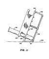
- the rack is used as a slant rack for holding test tubes and their contents at a predetermined angle (one such tube 100 and its contents are shown).
- the modified intermediate tier 106 extends outward relative to the top tier 107 and the bottom tier 108 (both of which are substantially unmodified). Either the entire front edge of the intermediate tier 106 or a portion thereof (for example, a post) may form the outward extension.
- the support 101 it is preferable for the support 101 to extend from the front edge of the bottom tier 108 at an angle outward to the extension 102 of the intermediate tier 106.
- the front surface of the support 101 provides a stable surface for supporting the rack, when tilted, on a table or other surface 104, as shown in FIGURE 11.
- the invention is particularly well suited to providing a range of slant angles, the approximately 20° angle shown in FIGURE 11 being one such example.
- a close examination of FIGURE 11 reveals that the intermediate tier 106 also has a rear extension 105 which projects outward from the bottom and top tiers.
- the rear support 103 which connects the extension 105 to the rear edge of the bottom tier 108, is inclined at an angle of about 5°.
- the test tubes 100 and their contents are oriented at about 5°.
- the support 103 it is preferred, but not necessary, for the support 103 to extend between the outside edges of the extension 105 and the bottom tier 16.
- the support 103 orthe support 101 could instead extend at right-angles relative to the intermediate and bottom tiers.
- the invention is well suited to provide multitier racks having a variety of configurations.
- the arrangement of the top and bottom sets of bars advantageously permits the placement of interconnecting supports at various locations along and within the edges of the tiers.
- the invention has been described in relation to a three-tiered structure, having substantially parallel tiers with the same general rectangular periphery and having edges which are aligned substantially coplanar, the invention encompasses a broad range of shapes, dimensions and alignments of the tiers.
- the arrangement of the preferred rack of FIGURES 1 to 6 is particularly helpful in simplifying the design of the mouldwhich forms it, it may be desirable to absorb the added cost of a more complex mould in orderto configure the rack other than as illustrated.
- the edges of the tier or tiers may be desirable to extend one or more of the edges (or only a portion thereof) of one or more of the tiers.
- the edges of the tier or tiers, so extended would have other than a coplanar alignment with the edges of the other tiers.
- any of the tiers, including the intermediate may be arranged at an angle relative to any of the other tiers.
- the inventive concepts broadly cover a rack having a plurality of spaced selectively interconnected tiers, at least one intermediate tier of which has a top set of bars and a bottom set of bars.
- the bars within each set it is not essential for the bars within each set to be parallel to one another or for such bars to extend the full distance between the edges of the intermediate tier.
- either or both of the top and bottom sets of bars may consist of groups of bars, the bars within each group being substantially parallel to one another.
- the configuration of the intermediate tier with such groups of parallel bars would complicate mould design, it would provide a greater variety of configurations for the apertures within a given rack and, hence, provide a means for holding or grouping test tubes or other articles having divergent shapes. Since the individual bars within a given group within the top set of bars would not necessarily overlap each of the bars within the bottom set (or groups of bars within the bottom set), there would be only selective intersection and superposition of the various bars. That is to say, only selected bars within the top set would be superposed over and intersect with selected bars within the bottom set to define the apertures.
- undercuts mean protrusions which will preventthewithdrawal of the mould segments which form the components of the rack.
- the invention is intended to encompass any single-piece injection moulded rack, the intermediate tier of which has selectively superposed and intersecting top and bottom sets of bars, it is preferable for there to be no undercuts in the lattice of the intermediate tier in order to enable its formation with slides which move uniaxially.
- the rack is obtained by including an upper spacer or column 24 extending between the top and intermediate tier and a lower spacer 26 extending between the intermediate tier and the bottom tier.
- the spacers 24 and 26 may have a variety of cross-sectional shapes, such as circular, square, triangular or even a long thin rectangular plate, which would give the appearance of a wall, the illustrated spacers resemble a cross in section and, accordingly, exhibit good rigidifying strength.
- the top tier optionally includes a gusset 28 which depends from the lower surface 50 and extends frontward and rearward from the spacer 24, spanning a portion of the frong-to-rear dimension of the surface 50.
- posts 23 and elongated feet 25 may optionally be included on the lower surface of the bottom tier 16.
- the posts and spacers may be advantageously shaped and positioned to provide an interlocking fit with the apertures 11 in the top tier of another rack for stacking purposes.
- the rack in accordance with the invention can be made from any suitable injection moulding material, such as, for example, polyethylene, polypropylene, polystyrene, high-impact polystyrene, polycarbonate, polyamides, polyacetals and polyurethane.
- the injection moulding material can also contain fillers, for instance glass fibres, carbon black, carbon fibres, boron fibres, silica or titanium dioxide. Glass fibres are a preferred filling material.
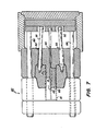
- FIGURES 7, 8 and 9 illustrate, in partial cross-sectional side elevation, the mould components and the sequential operation thereof to produce the rack.
- FIGURE 1 diagrammatically illustrates the movement and relationship of these components and will be referred to in order to facilitate an understanding of the more detailed views of FIGURES 7 to 9.
- certain features of the mould have been simplified or not shown.
- some sectional portions of the mould (and the moulded rack in FIGURES 7 and 8) have not been cross-hatched.
- the gating methods and techniques for introducing the molten plastics material into the mould are conventional, they are not shown or described in detail herein.
- a three-plate runner mould system is employed, although other systems may be used.
- the mould may be readily adapted for use in a wide variety of injection moulding machines which operate in either a vertical or horizontal manner and with any suitable injection mouldable material.
- FIGURES 7 to 9 illustrate the preferred disposition of the mould in a horizontal-type injection moulding machine.
- the mould includes a stationary, or injection, half 40 and a movable, or ejection, half 42.
- the ejection half 42 is movable along an axial path determined by four parallel leader pins 44 which are slidably journalled in bores located adjacent the corners of the mould. Movement of the ejection half 42 along the leader pins 44 between the mould-open position of FIGURE 8 and the mould-closed position of FIGURE 7 is controlled by means of a conventional hydraulic apparatus, not shown.
- the distance travelled by the ejection half 42 is somewhat foreshortened in the FIGURES, but is preferably about two to two-and-one-half times the dimensions of the moulded rack, so as to facilitate its ejection.
- the injection half 40 includes a runner system 41 through which plastics material is introduced into each of the portions of the mould cavity which form the three tiers.
- a rear slide 43 projects outwardly from a cavity 45 of the injection half 40.
- the lower surface 46 of the rear slide 43 is substantially planar and aligned generally parallel to the axial path of movement of the ejection half 42.
- channels 47 are milled into the lower surface 46 of the rear slide 43. These channels 47 correspond in cross-sectional dimension to the cross-sectional dimension of the top bars 15 of the rack 10 and in length to a predetermined portion of the overall length of the top bars 15.
- the channels 47 i.e., the longitudinal axes thereof, are aligned parallel to the axial path of movement of the ejection mould half 42.
- This alignment is illustrated in FIGURE 1 where the path of movement of the ejection half 42 is in the direction of the arrow extending from the rear slide 43 into the space between the top and intermediate tiers 12, 14 of the rack 10. It is to be understood that this arrow, as well as the other arrows in FIGURE 1, illustrate the relative (not necessarily actual) movement between the rack 10 and the parts of the mould which form it.
- FIGURE 1 the ejection half 42 of the mould.
- these elements are a front slide 31, a left core slide 60, a right core slide 70, an upper slide block 80, and a lower slide block 90.
- the front slide 31 is formed as part of a retainer block 30 and is flanked by an upper cavity 32 and a lower cavity 33.
- the front slide 31 cooperatively engages the rear slide 43 in face-to-face relation to define the portion of the mould cavity which forms the top bars 15 of the intermediate tier 14.
- the lower surface 34 of the front slide 31 includes parallel channels 35 which, in identical fashion to the channels 47 of the rear slide 43, correspond in cross-sectional dimensions to the cross-sectional dimensions of the top bars 15.
- the channels 35 in the front slide 31 mate end-to-end with the channels 47 of the rear slide 43 to form channels which correspond in length to the desired length of the top bars 15. While the bar length-determining function may be apportioned between the front and rear slides 31, 34, as discussed below, it is preferred for each of these slides to form half of the top set of bars 15.
- the longitudinal axes of the channels 35 are parallel to one another and to the axial path of movement of the ejection half 42 of the mould.
- the axes of the channels 35 lie within a plane substantially parallel to the plane of the lower surface 34.
- the front slide 31 and the rear slide 43 are mirror images of one another and to engage along a parting line which runs centrally through the cavity which forms the rack 10 (which corresponds with the parting line 56 on the rack, as shown in FIGURES 5 and 6).
- This parting line 56 is coincident with the parting line between the retainer block 30 and the injection half 40 and is indicated by the line labelled PL in FIGURES 8 and 9.
- the front and rear slides 31, 43 may be arranged to engage along a parting line which is not centrally located and, instead, is oriented in a plane which lies other than generally perpendicular to the direction of movement of the ejection half 42.
- the mating faces of the front and rear slides 31, 43 may be oriented in planes which are parallel to one another but at an angle relative to the path of movement of the ejection half 42.
- adjacent channels on each slide 31, 43 would gradually increase in length from a shortest channel to a longest channel.
- the engaging faces of these slides could be inclined toward one another so that the upper surfaces engage at a parting line which is offset (either to the front or to the rear) from the parting line of the lower surfaces.
- the front and rear slides 31, 43 each form half of the cavity corresponding to the top set of bars 15.
- the central engagement of the front and rear slides 31, 43 permits the inclusion of vertical channels 48 and 36 which cooperatively form the portion of the mould cavity corresponding to the upper spacer 24 of the rack 10.
- the upper surface 49 of the rear slide 43 and the upper surface 37 of the front slide 31 are each substantially planar and cooperate with the upper slide block 80 to form the portion of the mould cavity corresponding to the top tier 12 of the rack 10.
- the surfaces 49 and 37 preferably include a draft angle which tapers inwardly and downwardly toward the parting line 56, PL, i.e., toward the respective engaging faces of the rear and front slides 31, 43.
- the draft angles are preferably slight, from about 0.5° to 2°, in order to provide a generally planar appearance to the lower surface 50 of the top tier 12. In actuality, however, the presence of these draft angles moulds distinct planar front and rear portions of the lower surface of the top tier 12. If desired, of course, a much larger draft angle could be utilized.
- the upper surface 37 of the front slide 31 and the upper surface 49 of the rear slide 43 contain milled grooves or channels 36, 48, as shown in FIGURE 1, which dimensionally correspond to the desired dimensions of the gusset 28. If more than one gusset is desired, additional channels may be provided on these two surfaces 37, 49. In similar fashion to the channels 47 which form the top bars 15, the channels which form such gussets 28 are aligned parallel to the axial path of movement of the ejection mould half 42, so that the front and rear slides 31, 43 may be slidingly separated from the moulded gussets.
- the front slide 31 and rear slide 43 could optionally include on their engaging faces plural channels to form multiple upper spacers or, if desired, a single solid support which spans the entire length of the top and intermediate tiers 12, 14.
- a single slide could be used to form the top bars 15.
- Such a slide would include channels which span the entire front-to-rear length of the upper bars 15. The employment of such a slide would, however, not permit the formation of centrally-located spacers between the top and intermediate tiers 12, 14.
- the left core slide 60 and the right core slide 70 cooperate in similar fashion to the front and rear slides 31, 43 to help form the bottom bars 17 of the intermediate tier 14.
- the upper surfaces 61 and 71 of the left and right core slides 60, 70, respectively include parallel channels 62 and 72, respectively, which mate end-to-end to define the portion of the mould cavity corresponding to the bottom bars 17.
- These channels 62, 72 correspond in cross-sectional dimension to the cross-sectional dimension of the bottom bars 17 and in length to predetermined portions of the overall length of the bars 17.
- the channels 62, 72 are arranged with their longitudinal axes parallel to the axial paths of movement of the core slides 60 and 70.
- the core slides 60, 70 are movable along coaxial paths in opposed directions relative to one another and at right-angles to the axial path of movement of the ejection half 42. If it is desired to form a rack having top and bottom sets of bars which intersect other than at right-angles, then the axial paths of movement of the core slides 60, 70 would be oriented at some other angle relative to the axial path of movement of the ejection half 42. As shown in FIGURE 10, the core slides 60 and 70 move from their respective closed positions 60' and 70', shown in chaindotted lines, to their open positions, shown in solid lines, in which these slides 60, 70 are fully away from the moulded rack (not shown in FIGURE 10).
- FIGURE 10 In viewing FIGURE 10 in relation to FIGURES 7, 8 and 9, it is helpful to note that, because of the direction of view and the arbitrarily adopted directional convention, the right core slide 70 appears on the left in FIGURE 10, while the left core slide 60 appears on the right. Also, in the mould-closed position of FIGURE 7, the section is taken through the left core slide 60, while, in FIGURES 8 and 9, the left core slide 60 has been removed from view by virtue of the section (line 9-9 in FIGURE 10). Since the right core slide 70 has been omitted from FIGURES 8 and 9, the viewer is looking at the face of this slide in these figures (a portion of this face being hidden by the yet-to-be-ejected rack 10 in FIGURE 8).
- the lower surfaces 63, 73 of the left and right core slides 60, 70 are each substantially planar, but not necessarily coplanar with one another.
- a slight draft angle is also preferably provided for the lower surfaces 63 and 73.
- the surfaces 63 and 73 each taper inwardly and upwardly toward the parting line of the left and right core slides 60, 70.
- the engaging faces of the left and right core slides 60, 70 include vertical channels 64 and 74, respectively, which mate in the mould-closed position.
- the left and right core slides 60, 70 could optionally include on their engaging faces plural channels to form multiple lower spacers or, if desired, a single solid wall-like support which spans the entire front-to-back width of the intermediate and bottom tiers 14,16. It will be appreciated by those skilled in the art that the number, configuration and positioning of these spacer-forming channels may be varied greatly.
- the bottom tier 16 has sufficient rigidity so that additional gussets are not needed.
- gussets on its upper surface 19.
- such gussets for the bottom tier 16 may be formed by suitably milling channels into the lower surfaces 63 and 73 of the core slides, either as extensions of the channels 64 and 74 or as separate channels.
- the left and right core slides 60, 70 may have unequal lengths, so that their respective channels form unequal lengthwise portions of the bottom bars 17.
- the engaging faces of the core slides 60, 70 may meet in a plane which is inclined at an angle relative to the coaxial paths of movement of these two slides.
- the engaging faces of these two slides 60, 70 may be inclined toward one another so that the upper surfaces 61 and 71 engage at a parting line which is offset (either to the left or to the right) from the parting line of the lower surfaces 63 and 73.
- a similar arrangement may, of course, be employed for the front and rear slides 31 and 43.
- the left and right core slides 60, 70 include vertical surface portions 65 and 75, respectively, which have milled side channels 66 and 76, respectively, as shown best in FIGURE 1. When the mould is closed, the right side channel 76 cooperates with the right side surface portions 75 of the front and rear slides 31, 43, respectively, to form the portion of the mould cavity corresponding to the right side support 20.
- the left side channel 66 cooperates when the mould is closed with the left side surface portions 65 of the front and rear slides 31, 43 to form the portion of the mould cavity corresponding to the left side support 20 of the rack 10.
- the FIGURE 1 embodiment of the rack 10 includes a single side support 20, for purposes of clarity in this FIGURE.
- the surfaces 65 and 75 would have a pair of channels corresponding to the two side supports 20 on each of the left and right sides of the rack 10. It can be seen that a wide variety of configurations for the side supports 20 may be provided by altering the vertical surfaces 75 and 65 of the two core slides 60, 70.
- the side supports 20 may be positioned inwardly from the side edges, by altering the surfaces 65 and 75 of the core slides 60, 70 and the respective side surfaces of the front and rear slides 31, 43 with which they engage.
- the right side support 20 may be moved inward from the right side edges of the top and intermediate tiers 12,14.
- the surfaces 65 and 75 at an angle other than the generally vertical angle indicated in FIGURE 1, the side edges of the intermediate tier 14 may be moved outward relative to the side edges of the top tier 12.
- Such a reconfiguration would, of course, also incline the side supports 20 at an angle.
- the front and rear supports 21 and 22, respectively, are formed in an analogous fashion by channels which are formed in vertical surface portions 39 and 69, respectively, of the rear and front slides 43, 31, respectively. Only one channel 38 on the rear slide 43 is clearly seen in FIGURE 1, it being appreciated that there is a pair of channels in this surface, as well as a pair of channels in the surface portion 69 of the front slide 31.
- the vertical surface portions of the front and rear slides 31, 43 which contain the channels 38 may be variously configured to provide a wide variety of front and rear supports such as 21, 22.
- the vertical surface portion 39 of the rear slide 43 which contains the channel 38, cooperates when the mould is closed with rear surface portions of the left and right core slides 60, 70, while the vertical surface portion 69 of the front slide 31, which contains the channels 38 (which are not seen) cooperates when the mould is closed with front surface portions of the left and right core slides 60, 70.
- one such modification would provide a mould for forming the modified rack of FIGURE 11.
- the channels which form the front and rear supports are preferably configured to give the front and rear supports 21, 22 illustrated in FIGURE 2.
- the upper slide block 80 and the lower slide block 90 are releasably held within the upper cavity 32 and lower cavity 33, respectively, of the retainer block 30. These slide blocks 80, 90 remain seated in the retainer block 30 while the ejection half 42 moves from the mould-closed position of FIGURE 7 to the mould-open position of FIGURE 8.
- the upper slide block 80 and the lower slide block 90 are movable relative to the retainer block 30 along paths determined by an upper angular ejector pin 81 and a lower angular ejector pin 92, respectively.
- Both the upper and lower angular ejector pins 81, 92 are slidably journalled in respective bores disposed at an angle with respect to the axial path of movement of the ejection mould half 42. Journalling of the angular ejector pins 81, 92 is accomplished with the aid of an upper boss 82 and a lower boss 93. The angular ejector pins 81, 92 are secured at their forward ends within the upper slide block 80 and the lower slide block 90, respectively.
- the angular ejector pins 81, 92 are conventionally secured in T bushings, to permit vertical travel of the ends when the ejector pins 81, 92 are driven forward through the angular path in the retainer block 30.
- the sequence of movement of the angular ejector pins 81 and 92 is shown in FIGURES 8 and 9. From the mould-open position of FIGURE 8, the angular ejector pins 81, 92 are driven forward by the forward travel of an ejector box 85, which travels along a path determined by leader pins 86 (preferably four, as shown in FIGURE 10).
- leader pins 86 preferably four, as shown in FIGURE 10
- the upper slide block 80 and lower slide block 90 are displaced away from one another and away from the moulded rack 10.
- the two slide blocks 80, 90 follow the angular path defined by the bores through the retainer block 30. This action withdraws the projecting pin cores 91 from the apertures formed in the bottom tier 16 of the rack 10 and also pulls the projecting pin cores 83 from the apertures formed on the top tier 12 of the rack 10.
- the projecting pin cores 83 on the upper slide block 80 cooperate with the upper surfaces 37 and 49 of the front and rear slides 31, 43, respectively, to define the portion of the mould cavity corresponding to the upper tier 12.
- the projecting pin cores 91 on the lower slide block 90 cooperate with the lower surfaces 63 and 73 of the left core slides 60 and 70, respectively, to define that portion of the mould cavity corresponding to the bottom tier 16 of the rack 10.
- plural ejector blades 95 are slidably journalled in the retainer block 30 in conventional fashion and these ejector blades 95 are activated by the ejector box 85 simultaneously with the angular ejection of the upper and lower slide blocks 80, 90.
- the ejector blades 95 engage the moulded rack 10 at points spaced along the front edge of the intermediate tier 14.
- FIGURE 9 it must be observed again that the face of the right core slide 70, which is visible and appears to be disposed beneath the ejector blade 95, is, in fact, displaced backward from the plane of the FIGURE and, hence, completely away from the moulded rack 10. This relative position is shown in FIGURE 10.
- the sequence of mould opening and ejection is as follows. First, the mould is fully opened to the position shown in FIGURE 8. Then the left core slide 60 and the right core slide 70 are withdrawn by conventional hydraulic apparatus (not shown). Thereafter, the upper slide block 80 and the lower slide block 90 are cammed off by the action of the angular ejector pins 81, 92 and the moulded rack 10 is ejected by the action of the ejector blades 95, all of which are actuated simultaneously by the ejector box 85.
- the mould has been described in its preferred embodiment, for the formation of the preferred embodiment of a three-tiered rack for holding test tubes, it is to be understood that the inventive concept embraces a mould for forming a single-piece rack having more than three tiers.
- the top tier 12 of the rack illustrated in FIGURE 1 could easily be formed as a second intermediate tier by first providing bottom bar- forming channels in the upper surfaces 49 and 37 of the rear and front slides 31, 43. A top set of bars would then be formed over this bottom set of bars by stacking an additional core slide (or a pair of core slides) over the left and right core slides 60, 70. To form the top bars on this second intermediate tier, this additional slide or slides would have channels milled in the lower surface or surfaces.
- the top tier above this intermediate tier could be formed, for example, by a cooperative arrangement similar to the cooperative action of the upper slide block 80 and the upper surfaces 37 and 49 of the front and rear slides.
- the number of slides may be increased and oriented at various angles relatively to one another and suitably chanelled to provide a wide variety of configurations to the intermediate tier 14.
- Such additional slides, or even the slides shown may also be modified to provide other than a rectangular periphery for one or more of the tiers. Such modifications may be particularly desirable where the mould is to be used to provide a rack to be used for purposes other than holding test tubes. For example, such modifications may be useful in packaging, storage and shipping various kinds of containers for liquids and the like.
Landscapes
- Engineering & Computer Science (AREA)
- Manufacturing & Machinery (AREA)
- Mechanical Engineering (AREA)
- Health & Medical Sciences (AREA)
- Clinical Laboratory Science (AREA)
- Chemical & Material Sciences (AREA)
- Chemical Kinetics & Catalysis (AREA)
- Moulds For Moulding Plastics Or The Like (AREA)
- Devices For Use In Laboratory Experiments (AREA)
Claims (37)
Applications Claiming Priority (2)
| Application Number | Priority Date | Filing Date | Title |
|---|---|---|---|
| US550574 | 1983-11-10 | ||
| US06/550,574 US4588095A (en) | 1983-11-10 | 1983-11-10 | Single-piece injection molded rack |
Publications (3)
| Publication Number | Publication Date |
|---|---|
| EP0142284A2 EP0142284A2 (fr) | 1985-05-22 |
| EP0142284A3 EP0142284A3 (en) | 1986-08-27 |
| EP0142284B1 true EP0142284B1 (fr) | 1990-09-26 |
Family
ID=24197747
Family Applications (1)
| Application Number | Title | Priority Date | Filing Date |
|---|---|---|---|
| EP84307121A Expired EP0142284B1 (fr) | 1983-11-10 | 1984-10-17 | Rayon moulé d'une seule pièce et moule à injection pour sa fabrication |
Country Status (7)
| Country | Link |
|---|---|
| US (1) | US4588095A (fr) |
| EP (1) | EP0142284B1 (fr) |
| JP (1) | JPS60129142A (fr) |
| AU (1) | AU573757B2 (fr) |
| CA (1) | CA1215946A (fr) |
| DE (1) | DE3483307D1 (fr) |
| IE (1) | IE56315B1 (fr) |
Cited By (1)
| Publication number | Priority date | Publication date | Assignee | Title |
|---|---|---|---|---|
| US5993745A (en) * | 1998-03-04 | 1999-11-30 | Roche Diagnostics Corporation | Archival storage tray for multiple test tubes |
Families Citing this family (34)
| Publication number | Priority date | Publication date | Assignee | Title |
|---|---|---|---|---|
| USD300152S (en) | 1985-12-04 | 1989-03-07 | Jefsteel Business Equipment Corp. | Stationery rack or similar article |
| USD305035S (en) | 1986-12-19 | 1989-12-12 | Wendell R. Brooks, Inc. | Computer paper tray |
| US5080232A (en) * | 1989-06-01 | 1992-01-14 | Nalge Company | Test tube rack and retainer |
| DE4036178A1 (de) * | 1990-11-14 | 1992-05-21 | Schaefer Gmbh Fritz | Aus kunststoff hergestellter lager- und transportkasten |
| USD330621S (en) | 1991-02-06 | 1992-10-27 | Rehrig-Pacific Company, Inc. | Nestable can tray column |
| US5141117A (en) * | 1991-10-31 | 1992-08-25 | Olsen Leanora B | Tube display device |
| JPH0653330U (ja) * | 1993-01-07 | 1994-07-19 | 主税 上村 | スイッチ代用シートベルトのバックル |
| US5361914A (en) * | 1993-10-05 | 1994-11-08 | Digital Equipment Corporation | Device for component processing |
| US5585070A (en) * | 1994-04-29 | 1996-12-17 | Phoenix International Life Sciences Inc. | Method for extraction, extraction cartridge and automated extraction processing system |
| US6193064B1 (en) * | 1998-11-04 | 2001-02-27 | J. G. Finneran Associates, Inc. | Multi-tier vial plate |
| US6062398A (en) * | 1999-07-21 | 2000-05-16 | Thalmayr; Hermann | Insert for holding test tubes in a conveyor capsule of a pneumatic tube conveyor system |
| US7220590B2 (en) * | 2001-03-14 | 2007-05-22 | Beckman Coulter, Inc. | Conductive plastic rack for pipette tips |
| US20050241333A1 (en) * | 2003-12-03 | 2005-11-03 | Hamilton Robert W | Rate-controlled freezer and cooling methods thereof |
| USD506833S1 (en) * | 2004-01-23 | 2005-06-28 | Wescott, Iii Harvey M. | Test platform |
| USD507658S1 (en) * | 2004-01-27 | 2005-07-19 | Wescott, Iii Harvey M. | 8GC platform |
| USD537653S1 (en) * | 2004-08-06 | 2007-03-06 | Yung-Yuan Liu | Toolstand |
| USD511916S1 (en) * | 2004-11-30 | 2005-11-29 | It's Academic Of Illinois, Inc. | Locker shelf |
| US20060178056A1 (en) * | 2004-12-24 | 2006-08-10 | Daisan Co., Ltd. | Plastic product and its mold and applicable product thereof |
| US20080210590A1 (en) * | 2006-01-23 | 2008-09-04 | Cieri Christopher W | Golf club cleaning device and associated storage device |
| JP2008076135A (ja) * | 2006-09-20 | 2008-04-03 | Murazumi Kogyo Kk | 顕微鏡標本容器用ラック |
| JP2008096618A (ja) * | 2006-10-11 | 2008-04-24 | Murazumi Kogyo Kk | 顕微鏡標本容器用ラック |
| US7731039B1 (en) * | 2007-09-10 | 2010-06-08 | Walgreen Co. | Retail display |
| USD577513S1 (en) * | 2007-12-17 | 2008-09-30 | Peak Innovations Inc. | Display stand |
| EP2216159A1 (fr) | 2009-02-05 | 2010-08-11 | Etervind AB | Ensembles d'éjection pur systèmes de moulage par injection |
| BE1018828A3 (nl) * | 2009-07-16 | 2011-09-06 | Praet Peter Van | Intelligent rek voor specimen buisjes en werkwijze om de buisjes in het rek te laden. |
| BRPI1100578B1 (pt) * | 2011-01-31 | 2020-12-29 | Juan Carlos Calabrese Muzzi | molde e processo de obtenção de quadro de bicicleta em polímero reciclável e dito quadro de bicicleta |
| DK178973B1 (en) * | 2015-02-06 | 2017-07-17 | Cedrex As | Turn-secure rack |
| US20180238488A1 (en) * | 2017-02-21 | 2018-08-23 | Tree Cloud LLC | Digital Reality Equipment Resting Stand |
| US10300487B2 (en) * | 2017-07-11 | 2019-05-28 | Biosurfit, S.A. | Pipette holder |
| USD870808S1 (en) * | 2018-03-26 | 2019-12-24 | Ningbo Conda Art Material Group Co., Ltd. | Pen holder |
| JP7079657B2 (ja) * | 2018-05-23 | 2022-06-02 | 株式会社中央ハイテック | 金型を用いたスライド部材を備えた3構成物品の同時成形方法及びその金型 |
| JP7117349B2 (ja) * | 2020-07-02 | 2022-08-12 | 本田技研工業株式会社 | 金型装置 |
| JP7493668B2 (ja) * | 2021-02-19 | 2024-05-31 | 株式会社日立ハイテク | 容器ホルダ、分析装置、容器ホルダの製造方法 |
| USD1087940S1 (en) * | 2024-01-11 | 2025-08-12 | John Charles Licitra | Cabinet platform |
Family Cites Families (47)
| Publication number | Priority date | Publication date | Assignee | Title |
|---|---|---|---|---|
| GB579562A (en) * | 1940-12-26 | 1946-08-08 | Cfcmug | Improvements in filters |
| US2566817A (en) * | 1948-12-09 | 1951-09-04 | Leader Electric Company | Mold for making plastic grids |
| US2556590A (en) * | 1949-03-28 | 1951-06-12 | Harry G Long | Molded plastic basket |
| DE839114C (de) * | 1950-09-19 | 1952-05-15 | Julius Kalthoff | Gestell fuer Reagensglaeser |
| US3154209A (en) * | 1961-10-19 | 1964-10-27 | Alfred M Wilhite | Bottle case |
| BE628594A (fr) * | 1962-03-22 | |||
| US3184071A (en) * | 1962-12-12 | 1965-05-18 | Eastman Kodak Co | Plastic case for containers |
| US3379315A (en) * | 1966-04-07 | 1968-04-23 | Maryland Plastics Inc | Test tube rack |
| US3424831A (en) * | 1966-07-11 | 1969-01-28 | Spatz Lab | Methods for injection molding |
| US3388807A (en) * | 1966-09-14 | 1968-06-18 | Ronald W. Emmitt | Test tube holder |
| US3509603A (en) * | 1967-01-09 | 1970-05-05 | Globe Union Inc | Apparatus for fabricating battery cases |
| US3456913A (en) * | 1967-02-21 | 1969-07-22 | Michael Lutz | Mold for making a container having an integrally molded two-piece hinge |
| GB1186491A (en) * | 1967-12-20 | 1970-04-02 | Press End Stanzwerke Paul Crae | Pallets |
| US3473197A (en) * | 1968-05-06 | 1969-10-21 | Mold & Tool Co Inc E W | Locked mold assembly |
| US3532221A (en) * | 1968-09-23 | 1970-10-06 | Harry K Kaluhlokalani | Beauty operator's permanent-wave tray |
| US3564660A (en) * | 1968-12-09 | 1971-02-23 | George Darnell | Injection molding machine |
| US3604566A (en) * | 1969-05-01 | 1971-09-14 | Douglas J Rem | Test tube holder |
| US3731899A (en) * | 1971-03-01 | 1973-05-08 | G Nuzzo | Apparatus for producing concrete blocks with undercut portions |
| US3767156A (en) * | 1971-05-17 | 1973-10-23 | Richardson Co | Lock mold assembly for a container mold |
| GB1371240A (en) * | 1971-07-02 | 1974-10-23 | Gpg Holdings Ltd | Containers |
| BE770714A (nl) * | 1971-07-30 | 1971-12-01 | Bekaert Sa Nv | Draadkrat. |
| US3778232A (en) * | 1971-11-26 | 1973-12-11 | J Mcmorrow | Blood typing system |
| US3977821A (en) * | 1972-01-21 | 1976-08-31 | Beatrice Foods Co. | Apparatus for making a partitioned container |
| FR2176614B1 (fr) * | 1972-03-22 | 1976-08-06 | Sacomat | |
| US4023769A (en) * | 1972-11-22 | 1977-05-17 | Andrew Corporation | Molding means having opposed core assemblies |
| US3972737A (en) * | 1973-06-18 | 1976-08-03 | The Richardson Company | Multi-partitioned thin-walled container |
| US3930780A (en) * | 1973-07-20 | 1976-01-06 | Beatrice Foods Co. | Injection molding apparatus for partitioned containers |
| US4029728A (en) * | 1974-05-12 | 1977-06-14 | Gkn Sankey Limited | Method of injection moulding pallets |
| US4124122A (en) * | 1976-04-21 | 1978-11-07 | Emmitt Ronald W | Test tube rack |
| US4040595A (en) * | 1976-08-09 | 1977-08-09 | Weatherchem Corporation | Injection molding machine |
| GB1535229A (en) * | 1977-01-19 | 1978-12-13 | Gpg Holdings Ltd | Plastics moulded containers |
| USD257390S (en) | 1978-07-07 | 1980-10-14 | Sybron Corporation | Test tube rack |
| US4332537A (en) * | 1978-07-17 | 1982-06-01 | Dusan Slepcevic | Encapsulation mold with removable cavity plates |
| GB2028213B (en) * | 1978-08-25 | 1982-09-22 | Wells & Hingley | Reducing deflection of cores during injection moulding |
| US4273416A (en) * | 1979-01-02 | 1981-06-16 | Blum Alvin S | Indicating test tube rack |
| US4235410A (en) * | 1979-02-22 | 1980-11-25 | Mccord Corporation | Reinforcement panel and mold for making same |
| US4281768A (en) * | 1979-08-10 | 1981-08-04 | Sommers Philip B | Assay tube rack |
| US4330257A (en) * | 1979-11-15 | 1982-05-18 | Husky Injection Molding Systems, Inc. | Turret-type injection-molding machine |
| DE7933743U1 (de) * | 1979-11-30 | 1980-04-17 | Heraeus-Christ Gmbh, 3360 Osterode | Gestell fuer zentrifugenroehrchen |
| USD264157S (en) | 1980-02-11 | 1982-05-04 | Dave Karsikas | Instrument holder |
| US4284603A (en) * | 1980-05-08 | 1981-08-18 | Abbott Laboratories | Test tube decanter rack |
| USD265126S (en) | 1980-05-08 | 1982-06-22 | Abbott Laboratories | Test tube rack or the like |
| US4328945A (en) * | 1980-07-28 | 1982-05-11 | General Motors Corporation | Battery container mold |
| DE8109516U1 (de) * | 1981-03-31 | 1981-08-27 | Fritz Schäfer GmbH Fabriken für Lager- und Betriebseinrichtungen, Salchendorf bei Neunkirchen, Kreis Siegen, 5908 Neunkirchen | Schubladen-magazin, insbesondere fuer die vorratshaltung und/oder lagerung von kleinteilen |
| US4362290A (en) * | 1981-07-17 | 1982-12-07 | Westminster Marketing, Inc. | Mold for plastic needlepoint sheet |
| US4407958A (en) * | 1981-12-09 | 1983-10-04 | Sybron Corporation | Slant culture tube rack |
| US4495150A (en) * | 1983-07-25 | 1985-01-22 | Beckman Instruments, Inc. | Multiple object capturing and processing device |
-
1983
- 1983-11-10 US US06/550,574 patent/US4588095A/en not_active Expired - Lifetime
-
1984
- 1984-09-03 IE IE2254/84A patent/IE56315B1/xx unknown
- 1984-09-10 AU AU32858/84A patent/AU573757B2/en not_active Ceased
- 1984-09-18 CA CA000463473A patent/CA1215946A/fr not_active Expired
- 1984-10-17 DE DE8484307121T patent/DE3483307D1/de not_active Expired - Lifetime
- 1984-10-17 EP EP84307121A patent/EP0142284B1/fr not_active Expired
- 1984-11-05 JP JP59231461A patent/JPS60129142A/ja active Granted
Cited By (1)
| Publication number | Priority date | Publication date | Assignee | Title |
|---|---|---|---|---|
| US5993745A (en) * | 1998-03-04 | 1999-11-30 | Roche Diagnostics Corporation | Archival storage tray for multiple test tubes |
Also Published As
| Publication number | Publication date |
|---|---|
| US4588095A (en) | 1986-05-13 |
| CA1215946A (fr) | 1986-12-30 |
| AU573757B2 (en) | 1988-06-23 |
| IE56315B1 (en) | 1991-06-19 |
| EP0142284A2 (fr) | 1985-05-22 |
| JPH0472582B2 (fr) | 1992-11-18 |
| AU3285884A (en) | 1985-05-16 |
| JPS60129142A (ja) | 1985-07-10 |
| IE842254L (en) | 1985-05-10 |
| DE3483307D1 (de) | 1990-10-31 |
| EP0142284A3 (en) | 1986-08-27 |
Similar Documents
| Publication | Publication Date | Title |
|---|---|---|
| US4588095A (en) | Single-piece injection molded rack | |
| US4588158A (en) | Single-piece injection molded rack | |
| US4143764A (en) | Shipper container for flasks | |
| EP3354589B1 (fr) | Structure de support permettant de supporter simultanément une pluralité de récipients pour substances destinées à des applications médicales, pharmaceutiques ou cosmétiques, élément de transport et récipient de transport ou d'emballage dotés de ladite structure | |
| DE60030785T2 (de) | Herstellungsmethoden für dünnwandige Mikroplatte | |
| CN101228260B (zh) | 培养插入物载体、培养插入物和培养插入物系统 | |
| US6206674B1 (en) | Injection molding apparatus with removable hetero-molding tools | |
| EP2035147B1 (fr) | Système de rangement modulaire pour liquides de laboratoire | |
| CN108000808B (zh) | 一种塑胶绕线盘注塑模具及其绕线盘 | |
| EP1829613A1 (fr) | Unité de stockage et système de transfert destinés au stockage et la préparation d'échantillons biologiques | |
| US8349279B2 (en) | Samples storage system for pharmaceutical development | |
| EP0230223B1 (fr) | Appareil de perfusion pour la culture de cellules vivantes et procédé pour la culture en perfusion | |
| EP0608401A1 (fr) | Incubateur. | |
| DE102015207617A1 (de) | Träger zum Aufnehmen und Lagern von Laborgefäßen | |
| DE20023186U1 (de) | Verbesserte dünnwandige Mikroplatte | |
| US20210178400A1 (en) | Combinable cavity tray, assembly of combinable cavity trays, method of manufacturing and use of a combinable cavity tray | |
| CA1225214A (fr) | Moule de support monobloc moule par injection | |
| HUT38791A (en) | Plastic honeycomb and method for breeding honey-bees of higher productivity and resistance as well as queen-bee cell of whole cell-wall height and method for breeding queen-bees of increased productivity | |
| GB1585587A (en) | Battery jar and method of making same | |
| US20230357692A1 (en) | Cell culture apparatus | |
| JP5865097B2 (ja) | 水処理用濾材及び浄化槽 | |
| WO2024211381A1 (fr) | Système modulaire reconfigurable et redimensionnable de stockage de récipients | |
| KR102578202B1 (ko) | 모듈형 배양 플레이트 조립체 및 모듈형 배양 플레이트 | |
| US20070251892A1 (en) | Samples storage system for pharmaceutical development | |
| AT503822A2 (de) | Gefässhalter und arbeitsweise bei dessen fertigung |
Legal Events
| Date | Code | Title | Description |
|---|---|---|---|
| PUAI | Public reference made under article 153(3) epc to a published international application that has entered the european phase |
Free format text: ORIGINAL CODE: 0009012 |
|
| AK | Designated contracting states |
Designated state(s): BE CH DE FR GB IT LI LU NL SE |
|
| PUAL | Search report despatched |
Free format text: ORIGINAL CODE: 0009013 |
|
| RHK1 | Main classification (correction) |
Ipc: B01L 9/06 |
|
| AK | Designated contracting states |
Kind code of ref document: A3 Designated state(s): BE CH DE FR GB IT LI LU NL SE |
|
| 17P | Request for examination filed |
Effective date: 19860819 |
|
| RAP1 | Party data changed (applicant data changed or rights of an application transferred) |
Owner name: NALGE COMPANY |
|
| 17Q | First examination report despatched |
Effective date: 19881005 |
|
| ITF | It: translation for a ep patent filed | ||
| GRAA | (expected) grant |
Free format text: ORIGINAL CODE: 0009210 |
|
| AK | Designated contracting states |
Kind code of ref document: B1 Designated state(s): BE CH DE FR GB IT LI LU NL SE |
|
| PG25 | Lapsed in a contracting state [announced via postgrant information from national office to epo] |
Ref country code: NL Effective date: 19900926 |
|
| PG25 | Lapsed in a contracting state [announced via postgrant information from national office to epo] |
Ref country code: LU Free format text: LAPSE BECAUSE OF NON-PAYMENT OF DUE FEES Effective date: 19901031 |
|
| PGFP | Annual fee paid to national office [announced via postgrant information from national office to epo] |
Ref country code: NL Payment date: 19901031 Year of fee payment: 7 |
|
| REF | Corresponds to: |
Ref document number: 3483307 Country of ref document: DE Date of ref document: 19901031 |
|
| ET | Fr: translation filed | ||
| PGFP | Annual fee paid to national office [announced via postgrant information from national office to epo] |
Ref country code: LU Payment date: 19901106 Year of fee payment: 7 |
|
| NLV1 | Nl: lapsed or annulled due to failure to fulfill the requirements of art. 29p and 29m of the patents act | ||
| EPTA | Lu: last paid annual fee | ||
| PLBE | No opposition filed within time limit |
Free format text: ORIGINAL CODE: 0009261 |
|
| STAA | Information on the status of an ep patent application or granted ep patent |
Free format text: STATUS: NO OPPOSITION FILED WITHIN TIME LIMIT |
|
| 26N | No opposition filed | ||
| ITTA | It: last paid annual fee | ||
| PGFP | Annual fee paid to national office [announced via postgrant information from national office to epo] |
Ref country code: SE Payment date: 19921014 Year of fee payment: 9 |
|
| PGFP | Annual fee paid to national office [announced via postgrant information from national office to epo] |
Ref country code: BE Payment date: 19921116 Year of fee payment: 9 |
|
| PG25 | Lapsed in a contracting state [announced via postgrant information from national office to epo] |
Ref country code: SE Effective date: 19931018 |
|
| PG25 | Lapsed in a contracting state [announced via postgrant information from national office to epo] |
Ref country code: BE Effective date: 19931031 |
|
| BERE | Be: lapsed |
Owner name: NALGE CY Effective date: 19931031 |
|
| EUG | Se: european patent has lapsed |
Ref document number: 84307121.8 Effective date: 19940510 |
|
| REG | Reference to a national code |
Ref country code: GB Ref legal event code: IF02 |
|
| PGFP | Annual fee paid to national office [announced via postgrant information from national office to epo] |
Ref country code: FR Payment date: 20031003 Year of fee payment: 20 |
|
| PGFP | Annual fee paid to national office [announced via postgrant information from national office to epo] |
Ref country code: GB Payment date: 20031016 Year of fee payment: 20 |
|
| PGFP | Annual fee paid to national office [announced via postgrant information from national office to epo] |
Ref country code: CH Payment date: 20031017 Year of fee payment: 20 |
|
| PGFP | Annual fee paid to national office [announced via postgrant information from national office to epo] |
Ref country code: DE Payment date: 20031030 Year of fee payment: 20 |
|
| PG25 | Lapsed in a contracting state [announced via postgrant information from national office to epo] |
Ref country code: LI Free format text: LAPSE BECAUSE OF EXPIRATION OF PROTECTION Effective date: 20041016 Ref country code: GB Free format text: LAPSE BECAUSE OF EXPIRATION OF PROTECTION Effective date: 20041016 Ref country code: CH Free format text: LAPSE BECAUSE OF EXPIRATION OF PROTECTION Effective date: 20041016 |
|
| REG | Reference to a national code |
Ref country code: GB Ref legal event code: PE20 |
|
| REG | Reference to a national code |
Ref country code: CH Ref legal event code: PL |