EP0142290B1 - Hauptzylinder mit innerem Behälter - Google Patents
Hauptzylinder mit innerem Behälter Download PDFInfo
- Publication number
- EP0142290B1 EP0142290B1 EP84307166A EP84307166A EP0142290B1 EP 0142290 B1 EP0142290 B1 EP 0142290B1 EP 84307166 A EP84307166 A EP 84307166A EP 84307166 A EP84307166 A EP 84307166A EP 0142290 B1 EP0142290 B1 EP 0142290B1
- Authority
- EP
- European Patent Office
- Prior art keywords
- master cylinder
- reservoir
- fluid
- bore
- working chamber
- Prior art date
- Legal status (The legal status is an assumption and is not a legal conclusion. Google has not performed a legal analysis and makes no representation as to the accuracy of the status listed.)
- Expired
Links
Images

Classifications
-
- B—PERFORMING OPERATIONS; TRANSPORTING
- B60—VEHICLES IN GENERAL
- B60T—VEHICLE BRAKE CONTROL SYSTEMS OR PARTS THEREOF; BRAKE CONTROL SYSTEMS OR PARTS THEREOF, IN GENERAL; ARRANGEMENT OF BRAKING ELEMENTS ON VEHICLES IN GENERAL; PORTABLE DEVICES FOR PREVENTING UNWANTED MOVEMENT OF VEHICLES; VEHICLE MODIFICATIONS TO FACILITATE COOLING OF BRAKES
- B60T11/00—Transmitting braking action from initiating means to ultimate brake actuator without power assistance or drive or where such assistance or drive is irrelevant
- B60T11/10—Transmitting braking action from initiating means to ultimate brake actuator without power assistance or drive or where such assistance or drive is irrelevant transmitting by fluid means, e.g. hydraulic
- B60T11/16—Master control, e.g. master cylinders
- B60T11/22—Master control, e.g. master cylinders characterised by being integral with reservoir
-
- B—PERFORMING OPERATIONS; TRANSPORTING
- B60—VEHICLES IN GENERAL
- B60T—VEHICLE BRAKE CONTROL SYSTEMS OR PARTS THEREOF; BRAKE CONTROL SYSTEMS OR PARTS THEREOF, IN GENERAL; ARRANGEMENT OF BRAKING ELEMENTS ON VEHICLES IN GENERAL; PORTABLE DEVICES FOR PREVENTING UNWANTED MOVEMENT OF VEHICLES; VEHICLE MODIFICATIONS TO FACILITATE COOLING OF BRAKES
- B60T11/00—Transmitting braking action from initiating means to ultimate brake actuator without power assistance or drive or where such assistance or drive is irrelevant
- B60T11/10—Transmitting braking action from initiating means to ultimate brake actuator without power assistance or drive or where such assistance or drive is irrelevant transmitting by fluid means, e.g. hydraulic
- B60T11/16—Master control, e.g. master cylinders
- B60T11/165—Single master cylinders for pressurised systems
-
- F—MECHANICAL ENGINEERING; LIGHTING; HEATING; WEAPONS; BLASTING
- F16—ENGINEERING ELEMENTS AND UNITS; GENERAL MEASURES FOR PRODUCING AND MAINTAINING EFFECTIVE FUNCTIONING OF MACHINES OR INSTALLATIONS; THERMAL INSULATION IN GENERAL
- F16D—COUPLINGS FOR TRANSMITTING ROTATION; CLUTCHES; BRAKES
- F16D25/00—Fluid-actuated clutches
- F16D25/08—Fluid-actuated clutches with fluid-actuated member not rotating with a clutching member
-
- F—MECHANICAL ENGINEERING; LIGHTING; HEATING; WEAPONS; BLASTING
- F16—ENGINEERING ELEMENTS AND UNITS; GENERAL MEASURES FOR PRODUCING AND MAINTAINING EFFECTIVE FUNCTIONING OF MACHINES OR INSTALLATIONS; THERMAL INSULATION IN GENERAL
- F16D—COUPLINGS FOR TRANSMITTING ROTATION; CLUTCHES; BRAKES
- F16D25/00—Fluid-actuated clutches
- F16D25/12—Details not specific to one of the before-mentioned types
-
- F—MECHANICAL ENGINEERING; LIGHTING; HEATING; WEAPONS; BLASTING
- F16—ENGINEERING ELEMENTS AND UNITS; GENERAL MEASURES FOR PRODUCING AND MAINTAINING EFFECTIVE FUNCTIONING OF MACHINES OR INSTALLATIONS; THERMAL INSULATION IN GENERAL
- F16D—COUPLINGS FOR TRANSMITTING ROTATION; CLUTCHES; BRAKES
- F16D25/00—Fluid-actuated clutches
- F16D25/12—Details not specific to one of the before-mentioned types
- F16D25/126—Details not specific to one of the before-mentioned types adjustment for wear or play
-
- F—MECHANICAL ENGINEERING; LIGHTING; HEATING; WEAPONS; BLASTING
- F16—ENGINEERING ELEMENTS AND UNITS; GENERAL MEASURES FOR PRODUCING AND MAINTAINING EFFECTIVE FUNCTIONING OF MACHINES OR INSTALLATIONS; THERMAL INSULATION IN GENERAL
- F16D—COUPLINGS FOR TRANSMITTING ROTATION; CLUTCHES; BRAKES
- F16D25/00—Fluid-actuated clutches
- F16D25/08—Fluid-actuated clutches with fluid-actuated member not rotating with a clutching member
- F16D2025/081—Hydraulic devices that initiate movement of pistons in secondary cylinders for actuating clutches, i.e. primary cylinders
Definitions
- This invention relates to a device for controll- ably supplying hydraulic pressure and particularly to a master cylinder particularly useful for activating a hydraulically controlled clutch of a motor vehicle.
- Motor vehicles employing manually shiftable transmissions typically include a manually actuated drive clutch.
- the clutch is employed to selectively couple and uncouple the motor vehicle engine output with the drive transmission thereby permitting gear changes.
- clutch actuation systems are currently employed. Mechanically actuated types employ linkages or cables to effect clutch engagement and disengagement.
- Another type, with which this invention is particularly adapted, employs a remotely mounted slave cylinder which responds to a hydraulic pressure source to cause engagement or disengagement of the clutch as a fluid pressure responsive piston is caused to translate within the slave cylinder bore.
- a clutch master cylinder which supplies the fluid pressure signal to the slave cylinder in response to forces applied to an internal slidable plunger exerted by foot pressure of the motor vehicle operator on a movable clutch pedal within the interior compartment of the vehicle.
- engagement and disengagement occurs due to reciprocal translation of a clutch release or throw-out bearing which engages rotating fingers of a clutch pressure plate. These fingers cause the clutch plate to selectively clamp or unclamp a clutch disc between itself and the engine flywheel, thereby effectuating the coupling and uncoupling function.
- Clutch discs are typically covered with friction material which wears through cycles of clutch actuation, therefore, means for compensating for such wear and its effect on the actuation system is needed.
- Hydraulically actuated clutch and brake master cylinders heretofore available employ a slidable plunger within a cylinder bore where the plunger is normally biased by spring force in a clutch engaged or brake disengaged position. Due to fluid displacement within the hydraulic circuit, which occurs as the friction material of the clutch plate or brake pad is worn away, a reservoir for hydraulic fluid must be provided for the master cylinder.
- fluid actuated master cylinders have employed a separate or integrally mounted container of hydraulic fluid mounted above the master cylinder such that as fluid displacement occurs, the reservoir could provide or accept fluid.
- CH-A-235179 discloses such a brake master cylinder in which the housing has a cylindrical bore divided into two sections of equal diameter by a wall, one section of the bore forming a working chamber in communication with the hydraulic circuit of the brake and in which a first spring-biassed plunger is slidable, and the second section of the bore forming a space which can communicate with a reservoir above the master cylinder and with the working chamber through valve means to accept or provide fluid as appropriate.
- the fluid reservoir it has been considered necessary for the fluid reservoir to be located above the master cylinder in order to prevent air ingestion within the hydraulic circuit and to provide gravity feed of fluid to the master cylinder.
- This requirement of mounting a fluid reservoir above the master cylinder requires an externally mounted reservoir or a machined master cylinder housing providing an integral reservoir disposed above the housing.
- the necessity of providing such a reservoir, besides adding costs, tends to limit the types of production techniques which may be employed in fabricating the master cylinder housing.
- a hydraulic fluid pressure-supplying master cylinder adapted to provide a hydraulic fluid pressure signal responsive to an external force load which pressure signal is applied to a hydraulic circuit wherein the capacity of said hydraulic circuit for said hydraulic fluid is variable
- said master cylinder comprising: a housing having an internal cylindrical bore with a first open end and a second closed end, said bore being divided into two sections, a first section of the bore adjacent said first open end forming a working chamber and a second section adjacent said closed end forming a reservoir cavity, first plunger means slidably disposed within said bore first section; said working chamber volume changing as said first plunger is caused to slide within said bore first section, said working chamber volume communicating with said hydraulic circuit via an outlet port; first spring means biasing said first plunger means towards said first open end; a second plunger means slidably disposed within said bore second section, second spring means biasing said second plunger away from said closed end; and check valve means communicating said hydraulic fluid within said working chamber with said reservoir when said external force load is removed and iso
- the fluid contained within the reservoir may be pressurized to a greater than atmospheric pressure so that it will act to provide a degree of boost to the hydraulic system.
- a low spring constant coil spring may be provided which biases a reservoir plunger within the reservoir to ensure that the hydraulic fluid therein is lightly compressed to avoid the introduction of atmospheric gases within the hydraulic circuit.
- Figure 1 is a longitudinal cross-sectional view of a clutch actuating master cylinder according to this invention illustrating the position of the constituent components when the clutch is in an engaged position and the fluid reservoir has not accepted an appreciable quantity of displaced hydraulic fluid.
- Figure 2 is another longitudinal cross-sectional view of the clutch master cylinder according to this invention illustrating the position of the constituent components when the clutch pedal is depressed thereby disengaging the clutch mechanism and further illustrating the position of the reservoir plunger when the reservoir has accepted a quantity of displaced hydraulic fluid.
- This figure further differs from the structures shown in Figure 1 in that the outlet port and the fill and bleed port fixtures are removed.
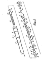
- FIG. 3 is an exploded pictorial view of the constituent parts of the clutch master cylinder according to this invention. Detailed description of the preferred embodiments of invention
- Housing 12 is formed from a cylindrical tube having a stepped internal bore which forms two different diameter sections, first diameter portion 14 and second diameter portion 16.
- First diameter portion 14 has a diameter greater than that of second diameter portion 16, thereby forming annular shoulder 17 therebetween.
- the exterior of housing 12 forms a cylindrical surface such that the wall of first diameter portion 14 forms an external diameter which is equal to or larger than the external diameter of the housing portion corresponding the second diameter portion 16.
- Housing 12 further forms radially extending flange 18 which acts to retain housing 12 in position with respect to mounting bracket 20 within which the housing is press fit or otherwise attached. Housing 12 further forms fill and bleed port 22 which is oriented in a vertically upward direction and downwardly directed outlet port 24. Housing 12 includes an opened end 26 formed adjacent first diameter portion 14 and closed end 28 which seals the end opposite 26 except that a small vent port 30 is provided which communicates the second internal diameter portion 16 with the atmosphere. Since the process of deep drawing of metal can . be employed to produce tubes with constant or successive decreasing diameter sections, this process may be employed to form housing 12. Deep forming is a process preferable to processes which involve extensive machining since cost reductions may be realized.
- Plunger 32 is disposed within first diameter portion 14 and is slidable therein.
- Plunger 32 includes annular sealing element 34 which is preferably constructed from an elastomeric substance which prevents hydraulic fluid leakage past plunger 32.
- Plunger 32 further forms dished out end 36.
- Mandrel portion 38 protrudes from the end of plunger 32 opposite end 36 and forms internal bore 40 opening in .the surface of the mandrel and extending coincident with the longitudinal axis of the plunger and which bore terminates within the plunger.
- Plunger mandrel portion 38 is shaped to accept spring retainer 42 which forms radially extending flange 44. A radially inward biased finger 43 of spring retainer 42 maintains the retainer in engagement with mandrel portion 38.
- Push rod 46 is shown centrally broken away and is operatively associated with the clutch actuating foot pedal (not shown) within the interior compartment of a motor vehicle.
- Push rod 46 forms enlarged head 48 which seats within dished out end 36 of plunger 32 when the push rod is forced to move to the left, with reference to the orientation displayed by the figures.
- Head 48 is kept in close proximity with plunger 32 by plunger head retainer 50 which is retained within housing open end 26 by snap ring 52 disposed with annular groove 54.
- Plug 56 Disposed within first internal diameter portion 14 at the junction between portion 14 and second diameter portion 16 is plug 56. Between plunger 32 and plug 56 is formed a variable volume working chamber 96. Plug 56 features internal bore 58 and annular cavity 60 which has an internal diameter greater than bore 58. Plug 56 has a sufficient external diameter to prevent it from entering second diameter portion 16 by seating against shoulder 17 and further includes hydraulic seal 62 disposed within annular groove 64 of the plug.
- Check valve assembly 66 seated within annular cavity 60 includes cup 68 closely fitting therein. Cavity 60 has an internal bore coincident with the cylindrical axis of plug 56. Cup 68 further forms a plurality of longitudinal cut out portions 69, best shown with reference to Figure
- valve stem member 72 spans between plunger 32 and plug 56 and includes plunger head 74 which causes the valve stem head to be trapped to move slidingly within internal bore 40.
- Plunger head 74 may be loaded into spring retainer 42 by providing a key slot 43 having an enlarged opening displaced from the longitudinal center of the retainer, which slot narrows at the center, thereby retaining the head when it is centrally positioned when so located by bore 40.
- the end of valve stem 72 opposite plunger head 74 forms plug head 76 and includes a radially extending flange surface 78 and a second radially extending flange . 80 with a reduced diameter segment 82 therebetween.
- Seal structure 70 cooperates with flanges 78 and 80 and portion 82 such that it is retained in association with plug head 76.
- Interposed between flange 78 and the internal end surface of cup 68 is wavy washer 84 which, in a free state, assumes a curved configuration such as is shown by Figure 2. In that condition, wavy washer 84 biases sealing structure 70 into sealing engagement with the radially projecting internal surface of plug 56 between bore 58 and annular cavity 60.
- Plunger return spring 86 is a helical spring which acts to bias plug 56 and plunger 32 apart. One end of return spring 86 engages radially extending flange 44 of spring retainer 42, while the other end contacts cup 68.
- reservoir plunger 88 Within second diameter portion 16 of housing 12 is slidably disposed reservoir plunger 88, which includes fluid seal 90 retained within annular groove 92. Reservoir plunger 88 is urged toward plug 56 by the action of helical reservoir plunger biasing spring 94. Between reservoir plunger 88 and plug 56 is formed variable volume reservoir 98 which, as will be subsequently explained, may contain a volume of hydraulic fluid. The other side of plunger 88, that is, the space between it and end 28, is vented to the atmosphere by port 30.
- FIG. 1 illustrates master cylinder 10 when no external load is applied to push rod 46 such that the clutch assumes an engaged position since a fluid pressure signal is not provided to the clutch actuating slave cylinder (not shown).
- plunger return spring 86 biases plunger 32 to the right until this motion is stopped by contact between the plunger and push rod head 48.
- contact between spring retainer 42 and valve stem plunger head 74 occurs exerting a tension load on valve stem 72.
- the spring constant of return spring 86 is chosen to be sufficiently great to cause compression of wavy washer 84 as it is compressed between flange 78 and cup 68.
- reservoir 98 will provide fluid to working chamber 96 which would occur, for example, when hydraulic fluid temperature changes causes a reduction in volume of the fluid within the fluid circuit. Therefore, reservoir 98 will provide or accept hydraulic fluid in accordance with the demands on the system.
- FIG. 2 illustrates master cylinder assembly 10 when push rod 46 is forcibly driven by an occupant operated push pedal within the interior compartment.
- plunger 32 is forced to move within working chamber 96 toward the left, thus causing an increase in the hydrostatic pressure therein.
- fluid is displaced from working chamber 96 to flow out of outlet port 24 to the fluid circuit, thereby causing actuation of a movable pressure sensitive element within the clutch actuating slave assembly.
- the formerly mentioned tension load on valve stem 72 is no longer exerted since, in this condition, head 74 is able to freely translate within bore 40 of plunger 32.
- sealing structure 70 acts as a check valve preventing fluid flow between the reservoir and the working chamber when push rod 46 is depressed. This action is necessary since, if fluid were permitted to communicate with reservoir 98, a sufficiently high hydrostatic fluid pressure could not be created to actuate the clutch slave cylinder. Through, repeated actuations of master cylinder 10, wear occurs within the clutch operating parts causing an increase in the volume of fluid which must be retained by the master cylinder and reservoir.
- reservoir plunger 88 over the course of time, slowly translates to the left, with reference to the orientations shown by the figures, thus causing the internally contained volume withiin the reservoir to increase over time.
- Reservoir plunger return spring 94 exerts a light compressive load on reservoir plunger 88 thereby causing a slight hydrostatic pressure within the fluid contained therein, thus effectively preventing the undesirable ingestion of air or other contaminants.
- the fluid pressure within the bore 96 and within the reservoir chamber 98 was atmospheric at the such times as the clutch was not operated due to deperssion of the clutch operating pedal and the push rod 46.
- the operation and construction of such an embodiment would be the same as that already described and, for that reason, it is not believed to be necessary to repeat the description of the construction and operation.
Landscapes
- Engineering & Computer Science (AREA)
- General Engineering & Computer Science (AREA)
- Mechanical Engineering (AREA)
- Transportation (AREA)
- Hydraulic Clutches, Magnetic Clutches, Fluid Clutches, And Fluid Joints (AREA)
Claims (9)
Applications Claiming Priority (4)
| Application Number | Priority Date | Filing Date | Title |
|---|---|---|---|
| US54950883A | 1983-11-07 | 1983-11-07 | |
| US633869 | 1984-07-23 | ||
| US06/633,869 US4679680A (en) | 1983-11-07 | 1984-07-23 | Clutch master cylinder with internal reservoir |
| US549508 | 1995-10-27 |
Publications (2)
| Publication Number | Publication Date |
|---|---|
| EP0142290A1 EP0142290A1 (de) | 1985-05-22 |
| EP0142290B1 true EP0142290B1 (de) | 1988-05-04 |
Family
ID=27069158
Family Applications (1)
| Application Number | Title | Priority Date | Filing Date |
|---|---|---|---|
| EP84307166A Expired EP0142290B1 (de) | 1983-11-07 | 1984-10-18 | Hauptzylinder mit innerem Behälter |
Country Status (4)
| Country | Link |
|---|---|
| US (1) | US4679680A (de) |
| EP (1) | EP0142290B1 (de) |
| CA (1) | CA1242400A (de) |
| DE (1) | DE3470920D1 (de) |
Families Citing this family (13)
| Publication number | Priority date | Publication date | Assignee | Title |
|---|---|---|---|---|
| GB8510778D0 (en) * | 1985-04-27 | 1985-06-05 | Lucas Ind Plc | Clutch actuating systems |
| US4856282A (en) * | 1987-05-12 | 1989-08-15 | Automotive Products Plc | Center-feed master cylinder with retainer for valve stem |
| US4823677A (en) * | 1988-01-19 | 1989-04-25 | General Electric Company | Brake power assist servomotor |
| US4949590A (en) * | 1988-02-17 | 1990-08-21 | Automotive Products Plc | Hydraulic cylinder assembly |
| US4924673A (en) * | 1988-02-17 | 1990-05-15 | Automotive Products Plc | Master cylinder with parallel-bore reservoir |
| GB8810553D0 (en) * | 1988-05-05 | 1988-06-08 | Smith D W | Integrated hydraulic pedal |
| AU4039889A (en) * | 1988-07-26 | 1990-02-19 | Automotive Products Plc | Hydraulic apparatus |
| FR2634832B1 (fr) * | 1988-07-26 | 1993-12-03 | Automotive Products France Sa | Appareil hydraulique |
| DE4240515A1 (de) * | 1992-12-02 | 1994-06-09 | Teves Gmbh Alfred | Hauptzylinder mit Plungerkolben und tiefgezogenem Stufengehäuse |
| FR2792688B1 (fr) * | 1999-04-22 | 2002-04-12 | Valeo | Cylindre hydraulique pour un dispositif de commande d'un embrayage de vehicule automobile |
| US20040025688A1 (en) * | 2002-08-12 | 2004-02-12 | Koekenberg Leonardus Gerhardus P. | Method and tools for manufacturing a master cylinder for a brake system, and cylinder manufactured therewith |
| US7197875B2 (en) * | 2005-03-24 | 2007-04-03 | Henifin Philip S | Hydraulic cylinder with coaxial, in-line reservoir |
| GB2475052B (en) * | 2009-11-03 | 2017-03-01 | Gm Global Tech Operations Llc | Double clutch actuation arrangement |
Family Cites Families (13)
| Publication number | Priority date | Publication date | Assignee | Title |
|---|---|---|---|---|
| US1786912A (en) * | 1927-10-21 | 1930-12-30 | Edward J Madden | Vehicle brake |
| DE716067C (de) * | 1940-01-13 | 1942-01-12 | Elektron Co M B H Berlin Haupt | Pumpe fuer Flugzeugbremsanlagen |
| DE759540C (de) * | 1941-01-20 | 1953-12-07 | Karl Muenz | Nachfuelleinrichtung fuer Druckzylinder von Fluessigkeitsbremsen, insbesondere fuer Kraftfahrzeuge |
| BE451064A (de) * | 1942-06-20 | |||
| US2525740A (en) * | 1946-11-19 | 1950-10-10 | Dunlop Rubber Co | Master cylinder |
| BE493682A (de) * | 1949-02-09 | |||
| US2758444A (en) * | 1952-08-13 | 1956-08-14 | John W White | Master cylinder assembly for hydraulic brakes |
| US3390524A (en) * | 1964-10-30 | 1968-07-02 | Girling Ltd | Hydraulic braking systems for vehicles |
| GB1153177A (en) * | 1965-09-03 | 1969-05-29 | Girling Ltd | Improvements in or relating to permanently coupled reservoir and master cylinder assemblies |
| DE2622976A1 (de) * | 1975-05-22 | 1976-12-02 | Girling Ltd | Hauptzylinder fuer fahrzeug-bremsanlagen |
| DE2856417A1 (de) * | 1978-12-28 | 1980-07-17 | Bosch Gmbh Robert | Hauptzylinder fuer eine hydraulische bremseinrichtung |
| DE3002850A1 (de) * | 1980-01-26 | 1981-07-30 | Audi Nsu Auto Union Ag, 7107 Neckarsulm | Geberzylinder |
| DE3120272A1 (de) * | 1981-05-21 | 1982-12-09 | Alfred Teves Gmbh, 6000 Frankfurt | Kupplungs-geberzylinder |
-
1984
- 1984-07-23 US US06/633,869 patent/US4679680A/en not_active Expired - Fee Related
- 1984-10-18 EP EP84307166A patent/EP0142290B1/de not_active Expired
- 1984-10-18 DE DE8484307166T patent/DE3470920D1/de not_active Expired
- 1984-10-31 CA CA000466770A patent/CA1242400A/en not_active Expired
Also Published As
| Publication number | Publication date |
|---|---|
| DE3470920D1 (en) | 1988-06-09 |
| EP0142290A1 (de) | 1985-05-22 |
| US4679680A (en) | 1987-07-14 |
| CA1242400A (en) | 1988-09-27 |
Similar Documents
| Publication | Publication Date | Title |
|---|---|---|
| US4679680A (en) | Clutch master cylinder with internal reservoir | |
| US4779713A (en) | Hydraulic clutch activation system | |
| US5036960A (en) | Apparatus and method of automotive brake with booster piston | |
| JPS643701B2 (de) | ||
| US4941323A (en) | Hydraulic cylinder provided with a seal-less piston | |
| US3004390A (en) | Fast acting servo mechanism | |
| US5024298A (en) | Apparatus and method of automotive brake with booster piston | |
| US5452779A (en) | Dual piston hydraulic cylinder for clutch and upshift brake actuator | |
| US5060776A (en) | Arrangement for controlling a hydraulically operated friction disc clutch with diaphragm spring | |
| US4354584A (en) | Transmission-clutch operating system | |
| US5189942A (en) | 3-position actuator | |
| CA1172297A (en) | Master cylinder | |
| US4785918A (en) | Pneumo-hydraulic converter for disc brake callipers | |
| EP0580675B1 (de) | Bremskraftverstaerker | |
| US4893473A (en) | Reservoir-formed shoulder stop for makeup fluid valve actuation in pull-type master cylinder | |
| JPS6111827B2 (de) | ||
| US3967447A (en) | Hydraulic master-slave clutch system | |
| EP0049969B1 (de) | Hauptzylinderaufbau für ein hydraulisches Fahrzeugbremssystem | |
| EP0090546A2 (de) | Notbremssystem | |
| US3009449A (en) | Brake booster | |
| EP0310733B1 (de) | Hydropneumatischer Betätiger für Kraftfahrzeuge | |
| US4921082A (en) | Fluid control cylinder assembly for automobile brake system | |
| JPH07501390A (ja) | クラッチ用従動シリンダ | |
| HU179418B (en) | Hydropneumatic control gear for synchronizing the clutch and transmission of motor vehicles | |
| JP2531530B2 (ja) | 二系統ブレ―キ弁用差圧制御機構 |
Legal Events
| Date | Code | Title | Description |
|---|---|---|---|
| PUAI | Public reference made under article 153(3) epc to a published international application that has entered the european phase |
Free format text: ORIGINAL CODE: 0009012 |
|
| AK | Designated contracting states |
Designated state(s): DE FR GB IT |
|
| 17P | Request for examination filed |
Effective date: 19851025 |
|
| 17Q | First examination report despatched |
Effective date: 19860910 |
|
| GRAA | (expected) grant |
Free format text: ORIGINAL CODE: 0009210 |
|
| AK | Designated contracting states |
Kind code of ref document: B1 Designated state(s): DE FR GB IT |
|
| ITF | It: translation for a ep patent filed | ||
| REF | Corresponds to: |
Ref document number: 3470920 Country of ref document: DE Date of ref document: 19880609 |
|
| ET | Fr: translation filed | ||
| PLBE | No opposition filed within time limit |
Free format text: ORIGINAL CODE: 0009261 |
|
| 26N | No opposition filed | ||
| PGFP | Annual fee paid to national office [announced via postgrant information from national office to epo] |
Ref country code: GB Payment date: 19900904 Year of fee payment: 7 |
|
| PGFP | Annual fee paid to national office [announced via postgrant information from national office to epo] |
Ref country code: FR Payment date: 19901009 Year of fee payment: 7 |
|
| ITTA | It: last paid annual fee | ||
| PGFP | Annual fee paid to national office [announced via postgrant information from national office to epo] |
Ref country code: DE Payment date: 19901206 Year of fee payment: 7 |
|
| PG25 | Lapsed in a contracting state [announced via postgrant information from national office to epo] |
Ref country code: GB Effective date: 19911018 |
|
| GBPC | Gb: european patent ceased through non-payment of renewal fee | ||
| PG25 | Lapsed in a contracting state [announced via postgrant information from national office to epo] |
Ref country code: FR Effective date: 19920630 |
|
| PG25 | Lapsed in a contracting state [announced via postgrant information from national office to epo] |
Ref country code: DE Effective date: 19920701 |
|
| REG | Reference to a national code |
Ref country code: FR Ref legal event code: ST |