EP0142359A2 - Gegenstrom-Ionenaustausch- und Adsorptionsverfahren - Google Patents
Gegenstrom-Ionenaustausch- und Adsorptionsverfahren Download PDFInfo
- Publication number
- EP0142359A2 EP0142359A2 EP84307787A EP84307787A EP0142359A2 EP 0142359 A2 EP0142359 A2 EP 0142359A2 EP 84307787 A EP84307787 A EP 84307787A EP 84307787 A EP84307787 A EP 84307787A EP 0142359 A2 EP0142359 A2 EP 0142359A2
- Authority
- EP
- European Patent Office
- Prior art keywords
- resin
- bed
- loading
- returned
- column
- Prior art date
- Legal status (The legal status is an assumption and is not a legal conclusion. Google has not performed a legal analysis and makes no representation as to the accuracy of the status listed.)
- Granted
Links
- 238000000034 method Methods 0.000 title claims abstract description 61
- 238000005342 ion exchange Methods 0.000 title claims abstract description 18
- 238000001179 sorption measurement Methods 0.000 title claims abstract description 7
- 239000011347 resin Substances 0.000 claims abstract description 209
- 229920005989 resin Polymers 0.000 claims abstract description 209
- 238000011068 loading method Methods 0.000 claims abstract description 90
- 239000007788 liquid Substances 0.000 claims abstract description 58
- 230000008929 regeneration Effects 0.000 claims abstract description 43
- 238000011069 regeneration method Methods 0.000 claims abstract description 43
- 238000011282 treatment Methods 0.000 claims abstract description 25
- 239000007785 strong electrolyte Substances 0.000 claims abstract description 10
- NWUYHJFMYQTDRP-UHFFFAOYSA-N 1,2-bis(ethenyl)benzene;1-ethenyl-2-ethylbenzene;styrene Chemical compound C=CC1=CC=CC=C1.CCC1=CC=CC=C1C=C.C=CC1=CC=CC=C1C=C NWUYHJFMYQTDRP-UHFFFAOYSA-N 0.000 claims abstract description 6
- 239000003456 ion exchange resin Substances 0.000 claims abstract description 6
- 229920003303 ion-exchange polymer Polymers 0.000 claims abstract description 6
- 239000003463 adsorbent Substances 0.000 claims abstract description 4
- 238000011001 backwashing Methods 0.000 claims description 44
- 239000012492 regenerant Substances 0.000 claims description 14
- 239000007787 solid Substances 0.000 abstract description 5
- 239000000356 contaminant Substances 0.000 abstract description 4
- XLYOFNOQVPJJNP-UHFFFAOYSA-N water Substances O XLYOFNOQVPJJNP-UHFFFAOYSA-N 0.000 description 30
- 230000000052 comparative effect Effects 0.000 description 19
- 238000012360 testing method Methods 0.000 description 16
- 238000012546 transfer Methods 0.000 description 13
- 239000008367 deionised water Substances 0.000 description 10
- 150000001768 cations Chemical class 0.000 description 9
- 238000005498 polishing Methods 0.000 description 7
- HEMHJVSKTPXQMS-UHFFFAOYSA-M Sodium hydroxide Chemical compound [OH-].[Na+] HEMHJVSKTPXQMS-UHFFFAOYSA-M 0.000 description 6
- 239000002253 acid Substances 0.000 description 6
- 150000001450 anions Chemical class 0.000 description 6
- 230000002378 acidificating effect Effects 0.000 description 4
- 239000003792 electrolyte Substances 0.000 description 4
- 239000000463 material Substances 0.000 description 4
- 238000009434 installation Methods 0.000 description 3
- 238000005406 washing Methods 0.000 description 3
- BVKZGUZCCUSVTD-UHFFFAOYSA-M Bicarbonate Chemical compound OC([O-])=O BVKZGUZCCUSVTD-UHFFFAOYSA-M 0.000 description 2
- 239000011324 bead Substances 0.000 description 2
- 230000001788 irregular Effects 0.000 description 2
- 238000004519 manufacturing process Methods 0.000 description 2
- 235000011121 sodium hydroxide Nutrition 0.000 description 2
- AFCARXCZXQIEQB-UHFFFAOYSA-N N-[3-oxo-3-(2,4,6,7-tetrahydrotriazolo[4,5-c]pyridin-5-yl)propyl]-2-[[3-(trifluoromethoxy)phenyl]methylamino]pyrimidine-5-carboxamide Chemical compound O=C(CCNC(=O)C=1C=NC(=NC=1)NCC1=CC(=CC=C1)OC(F)(F)F)N1CC2=C(CC1)NN=N2 AFCARXCZXQIEQB-UHFFFAOYSA-N 0.000 description 1
- BPQQTUXANYXVAA-UHFFFAOYSA-N Orthosilicate Chemical compound [O-][Si]([O-])([O-])[O-] BPQQTUXANYXVAA-UHFFFAOYSA-N 0.000 description 1
- 238000005349 anion exchange Methods 0.000 description 1
- 239000003957 anion exchange resin Substances 0.000 description 1
- 230000004888 barrier function Effects 0.000 description 1
- 238000005341 cation exchange Methods 0.000 description 1
- 125000002091 cationic group Chemical group 0.000 description 1
- 239000012141 concentrate Substances 0.000 description 1
- 238000011109 contamination Methods 0.000 description 1
- 230000003247 decreasing effect Effects 0.000 description 1
- 238000013461 design Methods 0.000 description 1
- 238000002474 experimental method Methods 0.000 description 1
- 238000001914 filtration Methods 0.000 description 1
- 239000012530 fluid Substances 0.000 description 1
- 239000012634 fragment Substances 0.000 description 1
- 230000005484 gravity Effects 0.000 description 1
- 238000010348 incorporation Methods 0.000 description 1
- 150000002500 ions Chemical class 0.000 description 1
- 239000006193 liquid solution Substances 0.000 description 1
- 239000000203 mixture Substances 0.000 description 1
- 238000012545 processing Methods 0.000 description 1
- 238000000746 purification Methods 0.000 description 1
- 239000012508 resin bead Substances 0.000 description 1
- 230000008961 swelling Effects 0.000 description 1
- 238000010626 work up procedure Methods 0.000 description 1
Images
Classifications
-
- B—PERFORMING OPERATIONS; TRANSPORTING
- B01—PHYSICAL OR CHEMICAL PROCESSES OR APPARATUS IN GENERAL
- B01D—SEPARATION
- B01D15/00—Separating processes involving the treatment of liquids with solid sorbents; Apparatus therefor
- B01D15/02—Separating processes involving the treatment of liquids with solid sorbents; Apparatus therefor with moving adsorbents
-
- B—PERFORMING OPERATIONS; TRANSPORTING
- B01—PHYSICAL OR CHEMICAL PROCESSES OR APPARATUS IN GENERAL
- B01J—CHEMICAL OR PHYSICAL PROCESSES, e.g. CATALYSIS OR COLLOID CHEMISTRY; THEIR RELEVANT APPARATUS
- B01J47/00—Ion-exchange processes in general; Apparatus therefor
- B01J47/02—Column or bed processes
-
- B—PERFORMING OPERATIONS; TRANSPORTING
- B01—PHYSICAL OR CHEMICAL PROCESSES OR APPARATUS IN GENERAL
- B01J—CHEMICAL OR PHYSICAL PROCESSES, e.g. CATALYSIS OR COLLOID CHEMISTRY; THEIR RELEVANT APPARATUS
- B01J49/00—Regeneration or reactivation of ion-exchangers; Apparatus therefor
- B01J49/60—Cleaning or rinsing ion-exchange beds
-
- B—PERFORMING OPERATIONS; TRANSPORTING
- B01—PHYSICAL OR CHEMICAL PROCESSES OR APPARATUS IN GENERAL
- B01J—CHEMICAL OR PHYSICAL PROCESSES, e.g. CATALYSIS OR COLLOID CHEMISTRY; THEIR RELEVANT APPARATUS
- B01J49/00—Regeneration or reactivation of ion-exchangers; Apparatus therefor
- B01J49/90—Regeneration or reactivation of ion-exchangers; Apparatus therefor having devices which prevent back-flow of the ion-exchange mass during regeneration
-
- B—PERFORMING OPERATIONS; TRANSPORTING
- B01—PHYSICAL OR CHEMICAL PROCESSES OR APPARATUS IN GENERAL
- B01D—SEPARATION
- B01D15/00—Separating processes involving the treatment of liquids with solid sorbents; Apparatus therefor
- B01D15/08—Selective adsorption, e.g. chromatography
- B01D15/10—Selective adsorption, e.g. chromatography characterised by constructional or operational features
- B01D15/18—Selective adsorption, e.g. chromatography characterised by constructional or operational features relating to flow patterns
- B01D15/1892—Selective adsorption, e.g. chromatography characterised by constructional or operational features relating to flow patterns the sorbent material moving as a whole, e.g. continuous annular chromatography, true moving beds or centrifugal chromatography
Definitions
- This invention is concerned with countercurrent ion exchange and adsorption processes in which loading is carried out by upward liquid flow and regeneration by downward liquid flow.
- the resin becomes polluted both with fragmented resin beads, which tend to concentrate at the top of the bed, and with solid contaminants introduced in the liquid to be treated. The latter tend to accumulate at the bottom of the bed.
- the space required for 100% bed expansion is also incompatible with the efficient upflow operation of a compact bed.
- British Patent 1 433 666 discloses a countercurrent ion exchange process wherein the whole resin is backwashed in segments by removing a part of the resin from the bottom of the bed, backwashing it in a separate column and re-inserting the backwashed resin at the top of the bed.
- This process by transferring to the polishing end of the bed resin which has been contacted with untreated water has the disadvantage that high volumes of regenerant have to be used to reform an adequately regenerated polishing section.
- the fragmented beads which tend to work up through the bed may not be adequately removed.
- British Patent 1 504 384 recognizes the disadvantage of destroying the polishing section in the above patent and attempts to overcome it by segmentally backwashing in a separate column, all of the resin in each backwashing step and returning each segment of the backwashed resin to the top of the bed so that the resin is returned, at the end of the backwash cycle when it has all been washed, to substantially its pre-backwashed position in the bed.
- This has the major disadvantage that the loading/regeneration cycle has to be seriously interrupted for backwashing.
- European Patent 30697 operates the loading, regeneration and backwashing steps in a column split into upper and lower parts by a resin barrier through which liquid can flow and which has a by-pass line through which resin is transferred to and from the bottom of the upper bed into the lower section so that the necessary free space for backwashing can be arranged in the upper bed and the resin can be returned to the upper bed before loading and, during loading, to help to offset the resin shrinkage.
- the loading/regeneration cycle has to be interrupted for resin transfer and backwashing.
- the transferred resin cannot be effectively backwashed without having such a large amount of free space in the split column that the column is uneconomic to operate and the resin in the bottom compartment will remain fluidized during loading so that the resin in this compartment is less efficiently utilized.
- an ion exchange or adsorption process for liquid treatment involving cyclical upflow loading and downflow regeneration stages applied to a compact bed of strong electrolyte ion exchange resin or of polymeric adsorbent wherein, without interrupting the cycle of loading and regeneration stages, part of the resin at or near one or other end of the bed is transferred, when in a regenerated state, into a separate container wherein the resin is backwashed and the backwashed resin is then returned to the top of the bed before, and/or to the bottom of the bed during, the loading stage, resin removed from the bottom of the bed being returned to the bottom of the bed and resin removed from the top of the bed being returned to the top and/or bottom of the bed.
- a portion of resin may be removed from the top of the bed to the separate backwashing column wherein it is backwashed and from which it is returned to the top of the bed. This is to remove fines, that is to say resin fragments, which tend to accumulate near the top of the bed.
- the resin removal will be carried out with the liquid which is used to rinse regenerant from the bed between the regeneration and loading stages. There is time to backwash this resin and return it to the top of the bed from where it has been removed before the next loading cycle commences.
- the resin In the case of ion exchange treatment of water, the resin would generally be backwashed and returned using treated water, usually deionised water. However in the case of other ion exchange treatments, such as sugar solution treatment, or in adsorption, these processes would be effected using separately provided deionised water.
- resin removed from the top of the bed may be returned to the bottom of the bed.
- resin removal may be effected by using the rinse liquid or by the first upflowing loading liquid so that backwashing can be effected and the resin returned to the bottom of the column during the loading cycle and while there is still time for this resin, which is of course in regenerated condition, to play an effective role in the liquid treatment.
- This embodiment does not preserve the polishing section of the column in the same way as the abovementioned first embodiment. Nevertheless, provided the amount of resin removed is judiciously chosen and removal is effected at or before an early enough stage in the loading cycle, the portion of resin immediately below the removed resin can form a sufficiently effective polishing section.
- the purpose of this embodiment is to enable the whole of the bed to be segmentally backwashed. The backwashing and resin return liquids would be as described above for the first embodiment.
- resin is taken from the top of the bed and some is returned to the top before loading begins and the remainder is returned to the bottom during loading. This enables sequential backwash of the whole bed to be achieved together with more frequent fines removal from the top of the bed while maintaining a compact bed during loading.
- resin is removed from the bottom of the bed and returned to the bottom of the bed. Removal will be conveniently effected with rinse liquid and return of the backwashed resin can conveniently be effected, once again using the backwashing liquid, which is either treated liquid in the case of ion exchange treatment or is deionised water separately provided as described above. Return of resin can take place at the beginning of the loading cycle, as soon as the upflowing loading liquid supports the bed to the point where space for the re-introduction is available, and further during the loading cycle as the resin in the column shrinks.
- This embodiment of the invention once again has the advantage that the resin re-introduced at the bottom of the column at the beginning of and during loading is regenerated resin which can play its full part in treatment of the loading liquid.
- washing the section of the resin at the top of the column tends to be carried out relatively frequently because the fines which accumulate at the top of the column tend to escape through and block the liquid exit nozzles. In many cases this has meant that an inert material to block fines has been added to the top of such compact beds. This use of inert material was largely an attempt to avoid the need to stop the loading/regeneration cycle in order to backwash the bed. The present invention therefore also may be used to avoid the incorporation of this inert material, with the obvious economy in column size and material usage.
- Removal of the resin from the top of the bed and reintroduction at the bottom in order to cycle the whole bed through the backwashing process is envisaged to be carried out rather less frequently since the process will generally not allow much build-up of contaminants in the middle section of the bed.
- the process of the present invention can be applied to a bed of resin in one compartment of a multi-compartment column.
- a bed of resin in one compartment of a multi-compartment column For example it is known in ion exchange to treat liquids in cation or anion exchange columns having two or more compartments separated by intermediate nozzle plates through which liquid, but not resin, may pass.
- Each compartment may be filled with the same strong or weak electrolyte resin or different compartments may be filled with different resins.
- the "bed" of strong resin to which this invention may be applied may be any such individual compartment in which a compact bed of strong electrolyte resin is to be operated or any combination of adjacent compartments which together are to be operated as such a bed. In the latter case provision may be made for resin to pass from one adjacent compartment to another containing the same resin to enable the cyclical washing embodiment of the invention to be carried out.
- a column may be split into a number of compartments of which some are to be operated as compact beds of strong electrolyte resin and others are not.
- the process of the invention may be applied to the compact bed(s) of resin but not to the others.
- a column has an upper compartment filled with a strong electrolyte resin and a lower compartment containing weak electrolyte resin.
- the former may be operated according to this invention but the latter cannot because weak electrolyte resin swells during loading so space must be left to accommodate this swelling.
- Such a weak electrolyte resin bed therefore operates at least during the initial part of the loading cycle as a partially fluidized bed.
- a common design involves an upper compartment filled with strong resin and a lower compartment only partially filled with the same resin, the resin in the upper compartment to be operated as a compact bed and that in the lower compartment to be operated as a fluidized, or partially fluidized, bed.
- the upper compartment may be operated according to this invention but the lower compartment will not.
- the lower compartment cannot operate as the backwash column for resin from the upper compartment or play any role in such backwash.
- Such a process would be similar to that of European Patent 30697 and, as described above, would involve the overwhelming disadvantage of substantial dislocation of the liquid treatment cycle while backwashing of the resin takes place.
- the invention may be applied to columns containing compact beds of strong electrolyte resin to be operated in series in which case the various options for resin movement parallel those for adjacent compartments filled with strong electrolyte resin as described above.
- the process of the invention may be applied to the treatment, by ion exchange or adsorption of a variety of fluids. Most frequently of course the deionisation of water is involved. However the purification treatment of other streams, for example sugar-containing liquids may be operated according to this invention.
- the process of the invention can be operated using any strong acid or strong base gel or macroreticular resin currently available and no limitation on strong electrolyte resins which might be developed in the future is contemplated.
- any crosslinked polymeric macroreticular adsorbent may be used as to adsorbants.
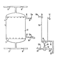
- One preferred embodiment of the invention can be carried out in equipment as schematically represented in Figure 1.
- an ion exchange column (1) is shown as a one-chamber column containing ion exchange resin (2).
- the column has a lower nozzle plate (3) and an upper nozzle plate (4).
- the liquid inlet/outlet piping at the lower end of the column comprises an inlet valved pipe (7) for liquid to be treated and outlet valved pipe (8) for the regeneration and rinse liquid.
- the liquid inlet/outlet piping at the upper end comprises outlet valved pipe (6) for the treated liquid solution and inlet valved pipe (5) for regenerant and rinse liquids.
- Two resin-transfer-lines (11) and (12) are equipped with valves (9) and (10) respectively and terminate in fast fitting connections (lla) and (12a).
- a separate open backwash vessel (13) large enough to provide for adequate expansion of resin to be transferred is connectable via inlet 14 (which is equipped with a fast fitting connection llb) and through liquid injector device (18) (with fast fitting connection 12b) to the column 1.
- inlet 14 which is equipped with a fast fitting connection llb
- liquid injector device (18) with fast fitting connection 12b
- flexible hoses (such as that depicted as 21) are used.
- a liquid injector (18) is fitted with valves (19) and (20), the former leading to the bottom of the vessel (13) and the latter leading to a liquid distributor (15), to ensure an even distribution of backwash liquid, via corresponding valve (16).
- An overflow (17) for backwash liquid is provided near the top of vessel 13.
- Inlet 22 is for backwashing liquid.
- the exchanger column (1) When the exchanger column (1) is constructed as multiple chamber column, it is internally separated by 3 or more nozzle plates into 2 or more chambers of the same or different volume. Piping at the top nozzle plate and bottom nozzle plate are identical to the one-chamber column depicted in Figure 1 but each chamber is equipped with two resin-transfer-openings as described for the single chamber of the column in Figure 1.
- the external equipment of such a multiple chamber column can correspond with that for one-chamber column, the useful volume of the open backwash vessel 13 being adjusted to provide adequate expansion of the volume of resin to be transferred from the biggest chamber.
- valve 8 was closed and 9 opened until 6 1 of resin had been transferred into the open backwash vessel 13 via a flexible pipe 21 and the inlet 14. Valve 9 was then closed and 8 reopened to finish the rinse.
- valve 16 By opening valve 16 the resin was backwashed (with deionised water) via backwash liquid distributor 15 and fines were removed. Valves 16 and 5 were then closed and after re-arranging the flexible pipe 21, valves 9, 19 and 20 were opened.
- the remaining resin in the open backwash vessel 13 was transferred into column 1 during the second half of the subsequent loading cycle.
- the flexible pipe 21 was connected to valve 10 and valves 10, 19 and 20 were opened.
- the upper chamber was filled completely with about 38 1 resin while the lower one is filled 54% by volume with about 22 1 resin.
- the backwash was carried out in the upper chamber. To obtain the necessary backwash space a part of the resin quantity from the upper chamber was transferred to the lower chamber using special equipment.
- the exchanger was loaded upflow during the exhaustion phase, that means valve 7 and 6 were open the rest remained closed.
- caustic soda regenerant as well as rinse water were passed through the resin bed downflow via valves 5 and 8.
- valve 8 was closed and 9 opened until 6 1 of resin had been transferred into the open backwash vessel 13 via the flexible pipe 21 and the inlet 14. Valve 9 was then closed and 8 reopened to finish the rinse.
- valve 16 By opening valve 16 the resin was backwashed with deionised water via backwash liquid distributor 15 and freed from fines. Valves 16 and 6 were closed and after re-arranging the flexible pipe 21, valves 9, 19 and 20 were opened.
- the resin remaining in the open backwash vessel 13 was transferred into column 1 during the second half of the following loading cycle.
- the flexible pipe 21 was connected to valve 10 and valves 10, 19 and 20 were opened.
- Example 2 To compare the performance in Example 2 to the known counter-current process with upflow loading, downflow regeneration and backwash possibilities in the column itself, 60 1 of resin of the same type were filled into a column of 200 mm internal diameter having 2 equal sized chambers with cylindrical jacket height of 1300 mm.
- the upper chamber was filled completely with about 38 1 resin while the lower one was filled 54% with about 22 1 resin.
- the backwash was carried out in the upper chamber.
- a part of the resin from the upper chamber was transferred to the lower chamber using special equipment. Two runs were carried out as in Comparative Test A. Table II shows the results of the loading cycle following the backwash of the resin.
- the exchanger was upflow loaded during the exhaustion phase, that means valve 7 and 6 were open, the rest remaining closed.
- valve 8 was closed and 10 opened until 10 1 of resin had been transferred into the open backwash vessel 13, via the flexible pipe 21 and the inlet 14. After that all valves were closed, the installation was put back into service.
- valve 16 By opening valve 16 the resin was backwashed with deionised water via backwash liquid distributor 15 and freed from suspended solids. Valve 16 was then closed and the flexible pipe was connected to the liquid injector 18.
- Valves 19,20 and 10 were opened and most of the backwashed resin was transferred back to the exchanger column 1 via liquid injector 18 the loading stage having been begun while backwashing was being carried out. Now, valves 19,20 and 10 were closed again. During the second half of the loading stage the remaining resin quantity in the open backwash-vessel was re-transferred in the same manner to the column 1.
- Example 3 For a comparison of the performance, the process of Example 3 was compared with the known processes: (a) a countercurrent process with upflow loading, downflow regeneration and with backwashing of exhausted resin in an external backwash vessel and (b) a countercurrent process with upflow loading, downflow regeneration and backwashing in the column itself.
- Example 3 The same process parameters as in Example 3 were applied.
- the upper chamber was filled completely with about 38 1 resin while the lower one was filled 54% with about 22 1 resin.
- the backwash was carried out in the lower chamber before every regeneration.
- the upper chamber was filled with a total of 39 1 of strong acid cation exchanger in Na-Form and the lower chamber with 38 1.
- the resin ionic form was changed into H-Form by treatment with 200 g HC1/1 of resin.
- the exchanger was upflow loaded during the exhaustion phase; during the regeneration phase the acidic regenerant as well as the rinse water were passed through the resin bed downflow.
- one backwash of the resin was performed during each cycle alternately backwashing resin from the upper chamber and resin from the lower chamber in alternate cycles.
- the upper chamber during the regeneration phase, after 0.9 BV rinse water had passed, 4 1 of resin were transferred via the upper chamber upper resin transfer opening into the open backwash vessel and after backwashing with deionised water most of the backwashed resin was returned to the column via the same upper resin transfer opening while regeneration was still in progress. During the second half of the loading stage the resin remaining in the open backwash vessel was re-transferred into the chamber via the upper chamber lower resin transfer opening.
- the lower chamber during the regeneration phase, after 0.9 BV rinse water had passed, 8 1 of resin were transferred via the lower chamber upper resin transfer opening into the open backwash vessel and after backwashing with deionised water most of the backwashed resin was returned at the beginning of the subsequent loading stage to the column, via the lower chamber lower resin transfer opening. During second half of the loading stage the remaining resin is transferred into the column via the same lower resin-transfer-opening.
- a column, with an internal diameter of 1194 mm and a cylindric jacket height of 3.200 mm is, via 3 nozzle plates separated into 2 equal sized chambers of about 1800 1 volume each.
- This column is equipped with an upper and lower resin transport openings in each of the two chambers and filled with a total of 3300 1 of a strong acid cation exchanger.
- the upper chamber is completely filled, the lower one has a bed depth of about 1440 mm.
- the lower chamber three times per 100 cycles at the end of the regeneration phase, as soon as about 1.5 BV rinse had passed, about 200 1 of resin were transferred into the open backwash vessel via the lower resin transport opening and backwashed with deionised water.
- the upper and lower chambers were not both backwashed during the same cycle.
- the lower chamber was completely filled with resin via the corresponding resin transfer opening of the upper chamber.
- Example 5 Comparative Test D These results show fundamental differences between the two processes.
- the water treated per cycle was lower due to the smaller resin volume, than in the Example, using the same column sizes.
Landscapes
- Chemical & Material Sciences (AREA)
- Chemical Kinetics & Catalysis (AREA)
- Organic Chemistry (AREA)
- Analytical Chemistry (AREA)
- Treatment Of Water By Ion Exchange (AREA)
- Saccharide Compounds (AREA)
- Organic Low-Molecular-Weight Compounds And Preparation Thereof (AREA)
Priority Applications (1)
| Application Number | Priority Date | Filing Date | Title |
|---|---|---|---|
| AT84307787T ATE37989T1 (de) | 1983-11-11 | 1984-11-09 | Gegenstrom-ionenaustausch- und adsorptionsverfahren. |
Applications Claiming Priority (2)
| Application Number | Priority Date | Filing Date | Title |
|---|---|---|---|
| GB838330229A GB8330229D0 (en) | 1983-11-11 | 1983-11-11 | Countercurrent ion exchange and absorption processes |
| GB8330229 | 1983-11-11 |
Publications (3)
| Publication Number | Publication Date |
|---|---|
| EP0142359A2 true EP0142359A2 (de) | 1985-05-22 |
| EP0142359A3 EP0142359A3 (en) | 1986-02-12 |
| EP0142359B1 EP0142359B1 (de) | 1988-10-19 |
Family
ID=10551666
Family Applications (1)
| Application Number | Title | Priority Date | Filing Date |
|---|---|---|---|
| EP84307787A Expired EP0142359B1 (de) | 1983-11-11 | 1984-11-09 | Gegenstrom-Ionenaustausch- und Adsorptionsverfahren |
Country Status (6)
| Country | Link |
|---|---|
| EP (1) | EP0142359B1 (de) |
| AT (1) | ATE37989T1 (de) |
| DE (1) | DE3474638D1 (de) |
| ES (1) | ES8602440A1 (de) |
| GB (1) | GB8330229D0 (de) |
| ZA (1) | ZA848773B (de) |
Cited By (3)
| Publication number | Priority date | Publication date | Assignee | Title |
|---|---|---|---|---|
| EP0551002A1 (de) * | 1992-01-10 | 1993-07-14 | Rohm And Haas Company | Ionenaustauscherkolonnen, solche aufweisende Systeme und solche Kolonnen verwendende Verfahren |
| RU2149685C1 (ru) * | 1999-11-26 | 2000-05-27 | Общество С Ограниченной Ответственностью "Объединение Иреа-Пензмаш" | Способ противоточной регенерации ионитов |
| WO2003049859A1 (en) * | 2001-12-10 | 2003-06-19 | Arianto Darmawan | A method of liquid purification using ion exchange resin being kept in a compacted state by means of elastic material |
Families Citing this family (3)
| Publication number | Priority date | Publication date | Assignee | Title |
|---|---|---|---|---|
| RU2185883C1 (ru) * | 2000-12-07 | 2002-07-27 | Балаев Игорь Семенович | Способ регенерации ионита в противоточном фильтре |
| RU2205692C2 (ru) * | 2002-02-06 | 2003-06-10 | Балаев Игорь Семенович | Способ ионообменной очистки воды, содержащей органические вещества, с противоточной регенерацией ионообменных материалов |
| CN117463410B (zh) * | 2022-07-21 | 2025-10-03 | 中国石油化工股份有限公司 | 一种体内清洗双室浮动床及清洗方法 |
Family Cites Families (5)
| Publication number | Priority date | Publication date | Assignee | Title |
|---|---|---|---|---|
| GB849979A (en) * | 1957-04-26 | 1960-09-28 | Permutit Co Ltd | Improvements relating to methods of and apparatus for bringing liquids into contact with granular materials |
| DE1767623C3 (de) * | 1968-05-30 | 1979-02-22 | Mannesmann Ag, 4000 Duesseldorf | Verfahren und Vorrichtung zum Entsalzen von Flüssigkeiten unter Verwendung von Ionenaustauschern |
| GB1318102A (en) * | 1970-03-11 | 1973-05-23 | Permutt Co Ltd | Ion-exchange treatment of water |
| GB1367085A (de) * | 1971-11-25 | 1974-09-18 | Permutit Co Ltd | |
| FR2443283A1 (fr) * | 1978-12-08 | 1980-07-04 | Degremont | Procede pour ameliorer le traitement de fluides contenant des particules en suspension sur des lits de matieres granulaires en vue d'en supprimer le colmatage |
-
1983
- 1983-11-11 GB GB838330229A patent/GB8330229D0/en active Pending
-
1984
- 1984-11-08 ES ES537547A patent/ES8602440A1/es not_active Expired
- 1984-11-09 AT AT84307787T patent/ATE37989T1/de not_active IP Right Cessation
- 1984-11-09 DE DE8484307787T patent/DE3474638D1/de not_active Expired
- 1984-11-09 ZA ZA848773A patent/ZA848773B/xx unknown
- 1984-11-09 EP EP84307787A patent/EP0142359B1/de not_active Expired
Cited By (4)
| Publication number | Priority date | Publication date | Assignee | Title |
|---|---|---|---|---|
| EP0551002A1 (de) * | 1992-01-10 | 1993-07-14 | Rohm And Haas Company | Ionenaustauscherkolonnen, solche aufweisende Systeme und solche Kolonnen verwendende Verfahren |
| RU2149685C1 (ru) * | 1999-11-26 | 2000-05-27 | Общество С Ограниченной Ответственностью "Объединение Иреа-Пензмаш" | Способ противоточной регенерации ионитов |
| WO2003049859A1 (en) * | 2001-12-10 | 2003-06-19 | Arianto Darmawan | A method of liquid purification using ion exchange resin being kept in a compacted state by means of elastic material |
| GB2396830A (en) * | 2001-12-10 | 2004-07-07 | Arianto Darmawan | A method of liquid purification using ion exchange resin being kept in a compacted state by means of elastic material |
Also Published As
| Publication number | Publication date |
|---|---|
| GB8330229D0 (en) | 1983-12-21 |
| ZA848773B (en) | 1985-07-31 |
| ATE37989T1 (de) | 1988-11-15 |
| ES537547A0 (es) | 1985-12-01 |
| ES8602440A1 (es) | 1985-12-01 |
| EP0142359A3 (en) | 1986-02-12 |
| EP0142359B1 (de) | 1988-10-19 |
| DE3474638D1 (en) | 1988-11-24 |
Similar Documents
| Publication | Publication Date | Title |
|---|---|---|
| US4519917A (en) | Counter-current adsorption filters for the treatment of liquids and a method of operating the filter | |
| US4461706A (en) | Apparatus for the countercurrent treatment of liquids with adsorbents | |
| US3231492A (en) | Fluid-solid contacting process | |
| US3679581A (en) | Method and apparatus for softening or desalting water by ion exchange | |
| CA1240419A (en) | Process and device for treating liquids with cation exchangers and anion exchangers | |
| KR100463268B1 (ko) | 혼상식(混床式) 당액 정제장치 및 그의 재생법 | |
| EP0142359B1 (de) | Gegenstrom-Ionenaustausch- und Adsorptionsverfahren | |
| US2771424A (en) | Process for regenerating ion exchange material | |
| US2841550A (en) | Process of operating a demineralizing installation | |
| EP0068412B1 (de) | Methode und Vorrichtung für eine Anlage mit einem in sich schichtweise beweglichen Ionenaustauscherbett | |
| US7422691B2 (en) | Method and apparatus for the demineralization of water | |
| US3875053A (en) | Process for carrying out ion exchange and adsorption processes using a countercurrent vessel | |
| AU640472B2 (en) | Ion exchange apparatus | |
| JPH10137751A (ja) | イオン交換方法及びこのイオン交換方法に用いられるイオン交換塔 | |
| US6228257B1 (en) | Apparatus for contacting fluids and solids | |
| US4269715A (en) | Process and apparatus for treating by ion exchange or adsorption fluids having solid particles suspended therein | |
| JP3632343B2 (ja) | 純水製造方法及びイオン交換塔 | |
| RU2206520C1 (ru) | Способ очистки воды от растворенных и нерастворенных примесей | |
| US3386914A (en) | Process of removing a component from a fluid | |
| US3351488A (en) | Ion exchange system | |
| JP3907012B2 (ja) | 向流再生式イオン交換装置とその再生方法 | |
| US3642616A (en) | Continuous method for treating liquids | |
| US3351550A (en) | Method for series water softening and series regeneration | |
| US4126548A (en) | Ion exchange process | |
| JP2654053B2 (ja) | 復水脱塩装置 |
Legal Events
| Date | Code | Title | Description |
|---|---|---|---|
| PUAI | Public reference made under article 153(3) epc to a published international application that has entered the european phase |
Free format text: ORIGINAL CODE: 0009012 |
|
| AK | Designated contracting states |
Designated state(s): AT BE CH DE FR GB IT LI LU NL SE |
|
| 17P | Request for examination filed |
Effective date: 19850924 |
|
| PUAL | Search report despatched |
Free format text: ORIGINAL CODE: 0009013 |
|
| AK | Designated contracting states |
Designated state(s): AT BE CH DE FR GB IT LI LU NL SE |
|
| 17Q | First examination report despatched |
Effective date: 19870421 |
|
| GRAA | (expected) grant |
Free format text: ORIGINAL CODE: 0009210 |
|
| AK | Designated contracting states |
Kind code of ref document: B1 Designated state(s): AT BE CH DE FR GB IT LI LU NL SE |
|
| REF | Corresponds to: |
Ref document number: 37989 Country of ref document: AT Date of ref document: 19881115 Kind code of ref document: T |
|
| ITF | It: translation for a ep patent filed | ||
| REF | Corresponds to: |
Ref document number: 3474638 Country of ref document: DE Date of ref document: 19881124 |
|
| ET | Fr: translation filed | ||
| PLBE | No opposition filed within time limit |
Free format text: ORIGINAL CODE: 0009261 |
|
| STAA | Information on the status of an ep patent application or granted ep patent |
Free format text: STATUS: NO OPPOSITION FILED WITHIN TIME LIMIT |
|
| 26N | No opposition filed | ||
| ITTA | It: last paid annual fee | ||
| EPTA | Lu: last paid annual fee | ||
| EAL | Se: european patent in force in sweden |
Ref document number: 84307787.6 |
|
| REG | Reference to a national code |
Ref country code: GB Ref legal event code: IF02 |
|
| PGFP | Annual fee paid to national office [announced via postgrant information from national office to epo] |
Ref country code: AT Payment date: 20031021 Year of fee payment: 20 |
|
| PGFP | Annual fee paid to national office [announced via postgrant information from national office to epo] |
Ref country code: NL Payment date: 20031022 Year of fee payment: 20 |
|
| PGFP | Annual fee paid to national office [announced via postgrant information from national office to epo] |
Ref country code: GB Payment date: 20031105 Year of fee payment: 20 |
|
| PGFP | Annual fee paid to national office [announced via postgrant information from national office to epo] |
Ref country code: FR Payment date: 20031119 Year of fee payment: 20 |
|
| PGFP | Annual fee paid to national office [announced via postgrant information from national office to epo] |
Ref country code: SE Payment date: 20031121 Year of fee payment: 20 Ref country code: CH Payment date: 20031121 Year of fee payment: 20 |
|
| PGFP | Annual fee paid to national office [announced via postgrant information from national office to epo] |
Ref country code: LU Payment date: 20031128 Year of fee payment: 20 |
|
| PGFP | Annual fee paid to national office [announced via postgrant information from national office to epo] |
Ref country code: DE Payment date: 20031231 Year of fee payment: 20 |
|
| PGFP | Annual fee paid to national office [announced via postgrant information from national office to epo] |
Ref country code: BE Payment date: 20040115 Year of fee payment: 20 |
|
| PG25 | Lapsed in a contracting state [announced via postgrant information from national office to epo] |
Ref country code: LI Free format text: LAPSE BECAUSE OF EXPIRATION OF PROTECTION Effective date: 20041108 Ref country code: GB Free format text: LAPSE BECAUSE OF EXPIRATION OF PROTECTION Effective date: 20041108 Ref country code: CH Free format text: LAPSE BECAUSE OF EXPIRATION OF PROTECTION Effective date: 20041108 |
|
| PG25 | Lapsed in a contracting state [announced via postgrant information from national office to epo] |
Ref country code: NL Free format text: LAPSE BECAUSE OF EXPIRATION OF PROTECTION Effective date: 20041109 Ref country code: LU Free format text: LAPSE BECAUSE OF EXPIRATION OF PROTECTION Effective date: 20041109 Ref country code: AT Free format text: LAPSE BECAUSE OF EXPIRATION OF PROTECTION Effective date: 20041109 |
|
| BE20 | Be: patent expired |
Owner name: *ROHM AND HAAS CY Effective date: 20041109 |
|
| REG | Reference to a national code |
Ref country code: CH Ref legal event code: PL |
|
| REG | Reference to a national code |
Ref country code: GB Ref legal event code: PE20 |
|
| EUG | Se: european patent has lapsed | ||
| NLV7 | Nl: ceased due to reaching the maximum lifetime of a patent |
Effective date: 20041109 |