EP0142381A2 - Opération de ramonage avec identification de paramètres du modèle - Google Patents
Opération de ramonage avec identification de paramètres du modèle Download PDFInfo
- Publication number
- EP0142381A2 EP0142381A2 EP84307947A EP84307947A EP0142381A2 EP 0142381 A2 EP0142381 A2 EP 0142381A2 EP 84307947 A EP84307947 A EP 84307947A EP 84307947 A EP84307947 A EP 84307947A EP 0142381 A2 EP0142381 A2 EP 0142381A2
- Authority
- EP
- European Patent Office
- Prior art keywords
- sootblowing
- heat
- boiler
- heat trap
- efficiency
- Prior art date
- Legal status (The legal status is an assumption and is not a legal conclusion. Google has not performed a legal analysis and makes no representation as to the accuracy of the status listed.)
- Withdrawn
Links
Images


Classifications
-
- F—MECHANICAL ENGINEERING; LIGHTING; HEATING; WEAPONS; BLASTING
- F23—COMBUSTION APPARATUS; COMBUSTION PROCESSES
- F23J—REMOVAL OR TREATMENT OF COMBUSTION PRODUCTS OR COMBUSTION RESIDUES; FLUES
- F23J3/00—Removing solid residues from passages or chambers beyond the fire, e.g. from flues by soot blowers
-
- F—MECHANICAL ENGINEERING; LIGHTING; HEATING; WEAPONS; BLASTING
- F22—STEAM GENERATION
- F22B—METHODS OF STEAM GENERATION; STEAM BOILERS
- F22B37/00—Component parts or details of steam boilers
- F22B37/02—Component parts or details of steam boilers applicable to more than one kind or type of steam boiler
- F22B37/56—Boiler cleaning control devices, e.g. for ascertaining proper duration of boiler blow-down
Definitions
- This invention relates to methods of and apparatus for identifying a parameter of a model for a rate of loss of boiler efficiency due to a sootblowing operation in one of a plurality of heat traps in the boiler.
- Furnace wall and convection-pass surf ⁇ es can be cleaned of ash and slag while in operation by the use of sootblowers using steam or air as a blowing medium.
- the sootblowing equipment directs product steam through retractable nozzles aimed at the areas where deposits . accumulate.
- the convection-pass surfaces in the boiler are divided into distinct sections in the boiler, e.g. superheater, reheater. and economizer sections.
- Each heat trap normally has its own dedicated set of sootblowing equipment. Usually, only one set of sootblowers is operated at any time, since the sootblowing operation consumes product steam and at the same time reduces the heat transfer rate of the heat trap being cleaned.
- Timing schedule is developed during initial operation and startup of the boiler.
- critical operating parameters such as gas side differential pressure, will interrupt the timing schedule when emergency plugging or fouling conditions are detected.
- the scheduling is usually set by boiler cleaning experts who observe boiler operating conditions and review fuel analyses and previous laboratory tests of fuel fouling.
- the sootblower schedule control settings may be accurate for the given operating conditions which were observed, but the combustion process is highly variable. There are constant and seasonal changes in load demand and gradual long term changes in burner efficiency and heat exchange surface cleanliness after sootblowing. Fuel properties can also vary for fuels such as bark, refuse, blast furnace gas, residue oils, waste sludge, or blends of coals. As a result, sootblowing scheduling based on several days of operating cycles may not result in the most economical or effective operation of the boiler.
- timing schedule is developed during initial operation and startup, and according to the above application, can be economically optimized for constant and seasonal changes in load demand, fuel variations, and gradual long term changes in burner efficiency and heat exchange surface cleanliness after sootblowing.
- a preferred embodiment of the present invention described hereinbelow provides a method and means of identifying the "fouling rate" of multiple sootblower groups for all types of combustion units.
- the identification can be done using combinations of "fouling rate” models for different heat traps, or any generalized set or grouping of sootblowers, as well as being applied to methods in which only one model type is assumed.
- the identification is accomplished using only a relative boiler or heat trap efficiency measurement, and does not require additional temperature inputs from throughout the boiler or heat trap.
- the implementation of this embodiment can be accomplished in microprocessor-based equipment such as the NETWORK 90 controller module. (NETWORK 90 is a trademark of the Bailey Controls Division of Babcock and Wilcox, a McDermott company).
- a method of identifying a parameter of a model for a rate of loss of boiler efficiency due to a sootblowing operation in one of a plurality of heat traps or groupings within a boiler comprising measuring the time since a last sootblowing operation in the heat trap (or grouping) in question, measuring an overall boiler efficiency at a beginning of the sootblowing operation for that heat trap (or grouping), the overall boiler efficiency being due to all heat traps present, measuring the change in efficiency in the boiler due to the sootblowing operation in the heat trap or grouping in question and calculating the parameter using an equation which relates the change in efficiency due to a particular sootblowing operation, to the overall efficiency of the boiler.
- the expression 'boiler includes not only items usually referred to as such, but also other convection heat transfer devices having a plurality of heat traps.
- a plurality of heat traps are usually provided.
- the heat traps lie in series with respect to the flow of combustion gases.
- platelets are provided which are followed, in the flow direction of the combustion gases, by a secondary superheater, a reheater, a primary superheater, and an economizer.
- the flow gases are then processed for pollution control and discharged from a stack or the like.
- Sootblowing equipment is operated as groupings (by reaction or region) so that portions of the boiler can be cleaned by sootblowing at spaced times while the boiler continues to operate.
- Each sootblowing operation has an adverse effect on the overall efficiency of the boiler, during the sootblowing operation proper.
- the sootblowing operation by reducing fouling, ultimately increases the efficiency of the particular heat trap being serviced.
- fouling rate models can be established which share the loss of efficiency over a period of time after a sootblowing operation, as the heat trap becomes fouled.
- the symbol B b is the time since the sootblower last ran in a boiler having only a single heat trap.
- the time ⁇ c is the time during which the sootblowing operation takes place.
- the loss of efficiency since the last sootblowing operation is a function of time as is the change in efficiency (increase) during the sootblowing operation.
- the identification of the adjustable model variable a 1 is easily done.
- the model can be evaluated as shown in Fig. 2 and in accordance with the relationship: where ⁇ E 1 is the change of overall boiler efficiency due to a sootblowing operation and E is the overall boiler efficiency since the beginning of the last sootblowing operation. - .
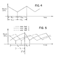
- Fig. 3 illustrates the case where two heat traps are provided and shows the effect of boiler efficiency due to these two traps separately. From outside the boiler, however, where the overall efficiency is measured, a composite curve is observed as illustrated in Fig. 4.
- the parameters a 1 for the i th heat trap, in the model, can be calculated from measuring this change and overall efficiency.
- the relationships for two heat traps with linear fouling models can be written: where AE 2 is the change in efficiency due to sootblowing in the second heat trap, ⁇ c2 is the time for sootblowing the second heat trap and ⁇ b2 is the time since the last sootblowing in the second heat trap.
- the fouling model for a boiler having three heat traps is illustrated in Fig. 5.
- the above analysis can be expanded and generalized by any number of heat traps with variable model types as follows: Where AE i is the change in efficiency due to sootblowing . in the i th heat trap or group of blowers and j is not equal to one (that is, a heat trap or group other than the heat trap for which the parameters a i is being calculated) and Tj is the time since sootblowing in the j th heat trap.
- the method embodying the present invention can be implemented using the NETWORK 90 as a microprocessor for effecting the various required steps and manipulations.
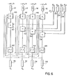
- conventional equipment such as temperature and oxygen sensors can be utilized to establish the ratio ⁇ E i /E in units 10, 12, 14, and 16, for each of four heat traps where i - 1, 2, 3, or 4.
- Suitable sensors and timers can also be utilized to determine the times since last sootblowing in each heat trap, as illustrated at units 20, 22, 24, and 26.
- the model parameters a 1 , a 2 , a3, and a4 are generated at output units 30, 32, 34, and 36.
- the logic circuit includes summing units 40, 42, 44, and 46 which receive the output of the respective efficiency units 10 to 16 and sum these outputs to a factor from each of the other heat traps.
- the output of . summing units 40 to 46 are multiplied by the appropriate time period for the respective heat traps in multiplication units 50, 52, 54, and 56.
- Limiters 60, 62, 64, and 66 are then provided to generate the parameter information and the factor to be added in the summing unit of each other heat trap.
- This logic circuitry performs a solution to a set of linear equations using a recursive technique.
- Parameter identification as set forth above can be utilized to optimize the sootblowing operation for each heat trap or group in accordance with our above-identified Patent Application No. EP-A-0 101 226 for sootblowing optimization.
- a set value for the time B b between sootblowing operations is compared to an optimum value B opt .
- the optimum cycle value B opt is attained as a function, not only of fouling and lost deficiency, but also a cost factor for the sootblowing operation. Specifically, one minimizes the expression of average loss:
- This optimum cycle time ( ⁇ b opt ) reflects economic considerations that affect the overall operation of the generating unit and is easily calculated.
- Comparators 80 to 83 obtain a difference between the optimum and set cycle times, with comparator 84 choosing the smallest difference.
- Comparators 86 to 89 as well as low limit detectors 90 to 97 are utilised.
- AND gates 98 to 101 compare Boolean logic signals and only the AND gate with all positive inputs is activated to perate its respective sootblowing euqipment which is connected to control elements 102 to 105 respectively.
- Sensing unit 110 establishes condition (a) by sensing whether any other blower is currently active. If no other blower is active, an on or one signal is provided to one of the three inputs of the AND gates 98 to 101.
- Condition (b) is established by low limit detectors 90 to 93 with condition (c) being established by low limit detectors 94 to 97.
- the heat trap designated 1 is considered the upstream most heat trap with the heat traps following in sequence to the last or downstream heat trap 4.
Landscapes
- Engineering & Computer Science (AREA)
- Mechanical Engineering (AREA)
- General Engineering & Computer Science (AREA)
- Physics & Mathematics (AREA)
- Thermal Sciences (AREA)
- Incineration Of Waste (AREA)
- Sampling And Sample Adjustment (AREA)
Applications Claiming Priority (2)
| Application Number | Priority Date | Filing Date | Title |
|---|---|---|---|
| US06/551,455 US4539840A (en) | 1983-11-14 | 1983-11-14 | Sootblowing system with identification of model parameters |
| US551455 | 2000-04-18 |
Publications (2)
| Publication Number | Publication Date |
|---|---|
| EP0142381A2 true EP0142381A2 (fr) | 1985-05-22 |
| EP0142381A3 EP0142381A3 (fr) | 1986-04-09 |
Family
ID=24201341
Family Applications (1)
| Application Number | Title | Priority Date | Filing Date |
|---|---|---|---|
| EP84307947A Withdrawn EP0142381A3 (fr) | 1983-11-14 | 1984-11-13 | Opération de ramonage avec identification de paramètres du modèle |
Country Status (9)
| Country | Link |
|---|---|
| US (1) | US4539840A (fr) |
| EP (1) | EP0142381A3 (fr) |
| JP (1) | JPS60108611A (fr) |
| KR (1) | KR890000452B1 (fr) |
| AU (2) | AU579585B2 (fr) |
| BR (1) | BR8404803A (fr) |
| CA (1) | CA1229533A (fr) |
| ES (1) | ES8600661A1 (fr) |
| IN (1) | IN162714B (fr) |
Cited By (2)
| Publication number | Priority date | Publication date | Assignee | Title |
|---|---|---|---|---|
| CN100595712C (zh) * | 2005-02-14 | 2010-03-24 | 艾默生过程管理电力和水力解决方案有限公司 | 改进蒸汽温度控制的方法和系统 |
| CN106402910A (zh) * | 2016-10-31 | 2017-02-15 | 上海电力学院 | 一种火电厂锅炉智能吹灰方法 |
Families Citing this family (17)
| Publication number | Priority date | Publication date | Assignee | Title |
|---|---|---|---|---|
| US4718376A (en) * | 1985-11-01 | 1988-01-12 | Weyerhaeuser Company | Boiler sootblowing control system |
| US5181482A (en) * | 1991-12-13 | 1993-01-26 | Stone & Webster Engineering Corp. | Sootblowing advisor and automation system |
| US6323442B1 (en) * | 1999-12-07 | 2001-11-27 | International Paper Company | System and method for measuring weight of deposit on boiler superheaters |
| US6928937B2 (en) * | 2002-12-26 | 2005-08-16 | Diamond Power International, Inc. | Sootblowing control based on boiler thermal efficiency optimization |
| US20040226758A1 (en) * | 2003-05-14 | 2004-11-18 | Andrew Jones | System and method for measuring weight of deposit on boiler superheaters |
| US7341067B2 (en) * | 2004-09-27 | 2008-03-11 | International Paper Comany | Method of managing the cleaning of heat transfer elements of a boiler within a furnace |
| US7890197B2 (en) * | 2007-08-31 | 2011-02-15 | Emerson Process Management Power & Water Solutions, Inc. | Dual model approach for boiler section cleanliness calculation |
| US8381690B2 (en) * | 2007-12-17 | 2013-02-26 | International Paper Company | Controlling cooling flow in a sootblower based on lance tube temperature |
| WO2010098946A2 (fr) * | 2009-02-24 | 2010-09-02 | Adams Terry N | Systèmes et procédés de commande de fonctionnement de souffleurs de suie |
| US20150007782A1 (en) * | 2012-01-25 | 2015-01-08 | It-1 Energy Pty Ltd | Method for detection and monitoring of clinker formation in power stations |
| US9541282B2 (en) | 2014-03-10 | 2017-01-10 | International Paper Company | Boiler system controlling fuel to a furnace based on temperature of a structure in a superheater section |
| US9927231B2 (en) * | 2014-07-25 | 2018-03-27 | Integrated Test & Measurement (ITM), LLC | System and methods for detecting, monitoring, and removing deposits on boiler heat exchanger surfaces using vibrational analysis |
| CA2955299C (fr) | 2014-07-25 | 2017-12-12 | International Paper Company | Systeme et procede pour la determination de localisation d'encrassement sur une surface de transfert de chaleur de chaudiere |
| CN104566413B (zh) * | 2015-01-06 | 2017-03-01 | 国家电网公司 | 一种快速选取锅炉吹管参数的方法 |
| US20210341140A1 (en) | 2020-05-01 | 2021-11-04 | International Paper Company | System and methods for controlling operation of a recovery boiler to reduce fouling |
| CN114046493A (zh) * | 2021-11-02 | 2022-02-15 | 国家能源集团华北电力有限公司廊坊热电厂 | 一种锅炉燃烧优化系统及终端 |
| CN114963213B (zh) * | 2022-04-14 | 2025-04-29 | 南京国电南自维美德自动化有限公司 | 一种适用于深度调峰和agc模式的锅炉吹灰操作方法及系统 |
Family Cites Families (4)
| Publication number | Priority date | Publication date | Assignee | Title |
|---|---|---|---|---|
| US2948013A (en) * | 1955-09-07 | 1960-08-09 | Blaw Knox Co | Program control for soot blowers |
| US3396706A (en) * | 1967-01-31 | 1968-08-13 | Air Preheater | Boiler cleaning control method |
| JPS5855609A (ja) * | 1981-09-30 | 1983-04-02 | Hitachi Eng Co Ltd | ス−トブロワの制御方法 |
| US4454840A (en) * | 1983-07-14 | 1984-06-19 | The Babcock & Wilcox Company | Enhanced sootblowing system |
-
1983
- 1983-11-14 US US06/551,455 patent/US4539840A/en not_active Expired - Fee Related
-
1984
- 1984-08-16 IN IN568/CAL/84A patent/IN162714B/en unknown
- 1984-09-04 KR KR1019840005420A patent/KR890000452B1/ko not_active Expired
- 1984-09-05 AU AU32746/84A patent/AU579585B2/en not_active Ceased
- 1984-09-07 JP JP59186647A patent/JPS60108611A/ja active Granted
- 1984-09-25 BR BR8404803A patent/BR8404803A/pt not_active IP Right Cessation
- 1984-09-26 ES ES536251A patent/ES8600661A1/es not_active Expired
- 1984-10-31 CA CA000466713A patent/CA1229533A/fr not_active Expired
- 1984-11-13 EP EP84307947A patent/EP0142381A3/fr not_active Withdrawn
-
1988
- 1988-09-07 AU AU21954/88A patent/AU2195488A/en not_active Abandoned
Cited By (3)
| Publication number | Priority date | Publication date | Assignee | Title |
|---|---|---|---|---|
| CN100595712C (zh) * | 2005-02-14 | 2010-03-24 | 艾默生过程管理电力和水力解决方案有限公司 | 改进蒸汽温度控制的方法和系统 |
| CN106402910A (zh) * | 2016-10-31 | 2017-02-15 | 上海电力学院 | 一种火电厂锅炉智能吹灰方法 |
| CN106402910B (zh) * | 2016-10-31 | 2018-09-28 | 上海电力学院 | 一种火电厂锅炉智能吹灰方法 |
Also Published As
| Publication number | Publication date |
|---|---|
| US4539840A (en) | 1985-09-10 |
| ES536251A0 (es) | 1985-10-16 |
| JPH0246845B2 (fr) | 1990-10-17 |
| EP0142381A3 (fr) | 1986-04-09 |
| BR8404803A (pt) | 1985-08-13 |
| CA1229533A (fr) | 1987-11-24 |
| ES8600661A1 (es) | 1985-10-16 |
| JPS60108611A (ja) | 1985-06-14 |
| KR850003968A (ko) | 1985-06-29 |
| IN162714B (fr) | 1988-07-02 |
| KR890000452B1 (ko) | 1989-03-17 |
| AU2195488A (en) | 1988-12-08 |
| AU579585B2 (en) | 1988-12-01 |
| AU3274684A (en) | 1985-05-23 |
Similar Documents
| Publication | Publication Date | Title |
|---|---|---|
| US4454840A (en) | Enhanced sootblowing system | |
| EP0142381A2 (fr) | Opération de ramonage avec identification de paramètres du modèle | |
| EP0137709B1 (fr) | Optimalisation du nettoyage des chaudières | |
| US4475482A (en) | Sootblowing optimization | |
| EP2126649B1 (fr) | Procédé et appareil pour une évaluation généralisée des performances d'un équipement, à partir de performances réalisables provenant de statistiques et de données en temps réel | |
| US4996951A (en) | Method for soot blowing automation/optimization in boiler operation | |
| US7890214B2 (en) | Method and apparatus for controlling soot blowing using statistical process control | |
| CN100595712C (zh) | 改进蒸汽温度控制的方法和系统 | |
| EP0101226B1 (fr) | Optimalisation de l'échappement de suie | |
| CN210197322U (zh) | 锅炉炉膛智能吹灰系统 | |
| Bujalski et al. | The algorithm of steam soot blowers operation based on the monitoring of fouling factors of heating surfaces of a coal-fired boiler under operating conditions | |
| CN120777546B (zh) | 一种循环流化床锅炉排烟温度预测系统及方法 | |
| SU1765614A1 (ru) | Способ управлени средствами очистки экранов топки паровых котлов | |
| JPS6367091B2 (fr) | ||
| JPS63286609A (ja) | スートブロワ制御装置 | |
| McGurn et al. | Heat transfer models for boiler fouling monitoring | |
| CN121488127A (zh) | 用于借助压力脉冲清洁抗压的锅炉的方法和用于所述方法的设备 | |
| Kumari et al. | Estimation of reheater cleanliness factor based on Kalman filtering method in neural network training | |
| JPH01266416A (ja) | ボイラに於けるスートブロワ運転制御方法 | |
| JPH01225808A (ja) | 煤吹機の制御方法 |
Legal Events
| Date | Code | Title | Description |
|---|---|---|---|
| PUAI | Public reference made under article 153(3) epc to a published international application that has entered the european phase |
Free format text: ORIGINAL CODE: 0009012 |
|
| AK | Designated contracting states |
Designated state(s): DE FR GB IT |
|
| PUAL | Search report despatched |
Free format text: ORIGINAL CODE: 0009013 |
|
| AK | Designated contracting states |
Kind code of ref document: A3 Designated state(s): DE FR GB IT |
|
| 17P | Request for examination filed |
Effective date: 19860921 |
|
| 17Q | First examination report despatched |
Effective date: 19880718 |
|
| STAA | Information on the status of an ep patent application or granted ep patent |
Free format text: STATUS: THE APPLICATION IS DEEMED TO BE WITHDRAWN |
|
| 18D | Application deemed to be withdrawn |
Effective date: 19881129 |
|
| RIN1 | Information on inventor provided before grant (corrected) |
Inventor name: SCHEIB, THOMAS J. Inventor name: KLATT, JOHN HENRY |