EP0142385A1 - Verfahren und Einrichtung zur Abbildung von Symbolen auf eine Flüssigkristallmatrixanzeige - Google Patents
Verfahren und Einrichtung zur Abbildung von Symbolen auf eine Flüssigkristallmatrixanzeige Download PDFInfo
- Publication number
- EP0142385A1 EP0142385A1 EP84401656A EP84401656A EP0142385A1 EP 0142385 A1 EP0142385 A1 EP 0142385A1 EP 84401656 A EP84401656 A EP 84401656A EP 84401656 A EP84401656 A EP 84401656A EP 0142385 A1 EP0142385 A1 EP 0142385A1
- Authority
- EP
- European Patent Office
- Prior art keywords
- image
- liquid crystal
- matrix
- crystal matrix
- rows
- Prior art date
- Legal status (The legal status is an assumption and is not a legal conclusion. Google has not performed a legal analysis and makes no representation as to the accuracy of the status listed.)
- Withdrawn
Links
- 239000011159 matrix material Substances 0.000 title claims abstract description 42
- 239000004973 liquid crystal related substance Substances 0.000 title claims abstract description 40
- 238000000034 method Methods 0.000 title claims description 12
- 230000015654 memory Effects 0.000 claims abstract description 10
- 230000005540 biological transmission Effects 0.000 claims abstract description 4
- 230000004913 activation Effects 0.000 claims description 8
- 238000001994 activation Methods 0.000 claims description 8
- 230000003287 optical effect Effects 0.000 claims description 8
- 210000002858 crystal cell Anatomy 0.000 claims description 4
- 238000004519 manufacturing process Methods 0.000 abstract description 3
- 239000011521 glass Substances 0.000 description 6
- 238000012163 sequencing technique Methods 0.000 description 5
- PEDCQBHIVMGVHV-UHFFFAOYSA-N Glycerine Chemical compound OCC(O)CO PEDCQBHIVMGVHV-UHFFFAOYSA-N 0.000 description 4
- 230000008033 biological extinction Effects 0.000 description 4
- 230000005684 electric field Effects 0.000 description 3
- 238000000354 decomposition reaction Methods 0.000 description 2
- 230000010287 polarization Effects 0.000 description 2
- 241001080024 Telles Species 0.000 description 1
- 230000000712 assembly Effects 0.000 description 1
- 238000000429 assembly Methods 0.000 description 1
- 230000008901 benefit Effects 0.000 description 1
- 239000013078 crystal Substances 0.000 description 1
- 230000009849 deactivation Effects 0.000 description 1
- 230000007423 decrease Effects 0.000 description 1
- 238000010586 diagram Methods 0.000 description 1
- 238000009826 distribution Methods 0.000 description 1
- 230000000694 effects Effects 0.000 description 1
- 239000007788 liquid Substances 0.000 description 1
- 230000003446 memory effect Effects 0.000 description 1
- 230000002093 peripheral effect Effects 0.000 description 1
- 230000008569 process Effects 0.000 description 1
- 230000004044 response Effects 0.000 description 1
- 239000007858 starting material Substances 0.000 description 1
- 238000003860 storage Methods 0.000 description 1
- 238000012800 visualization Methods 0.000 description 1
Images



Classifications
-
- G—PHYSICS
- G09—EDUCATION; CRYPTOGRAPHY; DISPLAY; ADVERTISING; SEALS
- G09G—ARRANGEMENTS OR CIRCUITS FOR CONTROL OF INDICATING DEVICES USING STATIC MEANS TO PRESENT VARIABLE INFORMATION
- G09G3/00—Control arrangements or circuits, of interest only in connection with visual indicators other than cathode-ray tubes
- G09G3/20—Control arrangements or circuits, of interest only in connection with visual indicators other than cathode-ray tubes for presentation of an assembly of a number of characters, e.g. a page, by composing the assembly by combination of individual elements arranged in a matrix no fixed position being assigned to or needed to be assigned to the individual characters or partial characters
- G09G3/34—Control arrangements or circuits, of interest only in connection with visual indicators other than cathode-ray tubes for presentation of an assembly of a number of characters, e.g. a page, by composing the assembly by combination of individual elements arranged in a matrix no fixed position being assigned to or needed to be assigned to the individual characters or partial characters by control of light from an independent source
- G09G3/36—Control arrangements or circuits, of interest only in connection with visual indicators other than cathode-ray tubes for presentation of an assembly of a number of characters, e.g. a page, by composing the assembly by combination of individual elements arranged in a matrix no fixed position being assigned to or needed to be assigned to the individual characters or partial characters by control of light from an independent source using liquid crystals
- G09G3/3611—Control of matrices with row and column drivers
- G09G3/3674—Details of drivers for scan electrodes
- G09G3/3681—Details of drivers for scan electrodes suitable for passive matrices only
-
- G—PHYSICS
- G09—EDUCATION; CRYPTOGRAPHY; DISPLAY; ADVERTISING; SEALS
- G09G—ARRANGEMENTS OR CIRCUITS FOR CONTROL OF INDICATING DEVICES USING STATIC MEANS TO PRESENT VARIABLE INFORMATION
- G09G3/00—Control arrangements or circuits, of interest only in connection with visual indicators other than cathode-ray tubes
- G09G3/20—Control arrangements or circuits, of interest only in connection with visual indicators other than cathode-ray tubes for presentation of an assembly of a number of characters, e.g. a page, by composing the assembly by combination of individual elements arranged in a matrix no fixed position being assigned to or needed to be assigned to the individual characters or partial characters
- G09G3/34—Control arrangements or circuits, of interest only in connection with visual indicators other than cathode-ray tubes for presentation of an assembly of a number of characters, e.g. a page, by composing the assembly by combination of individual elements arranged in a matrix no fixed position being assigned to or needed to be assigned to the individual characters or partial characters by control of light from an independent source
- G09G3/36—Control arrangements or circuits, of interest only in connection with visual indicators other than cathode-ray tubes for presentation of an assembly of a number of characters, e.g. a page, by composing the assembly by combination of individual elements arranged in a matrix no fixed position being assigned to or needed to be assigned to the individual characters or partial characters by control of light from an independent source using liquid crystals
- G09G3/3611—Control of matrices with row and column drivers
-
- G—PHYSICS
- G09—EDUCATION; CRYPTOGRAPHY; DISPLAY; ADVERTISING; SEALS
- G09G—ARRANGEMENTS OR CIRCUITS FOR CONTROL OF INDICATING DEVICES USING STATIC MEANS TO PRESENT VARIABLE INFORMATION
- G09G3/00—Control arrangements or circuits, of interest only in connection with visual indicators other than cathode-ray tubes
- G09G3/20—Control arrangements or circuits, of interest only in connection with visual indicators other than cathode-ray tubes for presentation of an assembly of a number of characters, e.g. a page, by composing the assembly by combination of individual elements arranged in a matrix no fixed position being assigned to or needed to be assigned to the individual characters or partial characters
- G09G3/34—Control arrangements or circuits, of interest only in connection with visual indicators other than cathode-ray tubes for presentation of an assembly of a number of characters, e.g. a page, by composing the assembly by combination of individual elements arranged in a matrix no fixed position being assigned to or needed to be assigned to the individual characters or partial characters by control of light from an independent source
- G09G3/36—Control arrangements or circuits, of interest only in connection with visual indicators other than cathode-ray tubes for presentation of an assembly of a number of characters, e.g. a page, by composing the assembly by combination of individual elements arranged in a matrix no fixed position being assigned to or needed to be assigned to the individual characters or partial characters by control of light from an independent source using liquid crystals
- G09G3/3611—Control of matrices with row and column drivers
- G09G3/3685—Details of drivers for data electrodes
- G09G3/3692—Details of drivers for data electrodes suitable for passive matrices only
Definitions
- the present invention relates to a method and a device for displaying symbols using a liquid crystal matrix.
- the symbols are produced by means of independent optical masks, either mobile or fixed. Usually, the movements of these symbols are obtained using mobile equipment possibly equipped with mirrors. However, the number of symbols generated by these systems is limited due to the complexity and the number of mechanical assemblies it makes intervene. In addition, these systems are relatively bulky and suffer from a certain fragility.
- cathode ray tube systems the screen of the cathode ray tube on which the symbols are generated, is arranged in the focal plane object of an optical system used for example to project these symbols on a semi-reflecting mirror. This solution has the advantage of visualizing very complex symbologies with high definition. On the other hand, it proves to be expensive and bulky, which considerably limits its field of application. In an attempt to avoid these drawbacks, we have therefore sought to produce display devices using, in optical systems similar to those used for cathode ray tubes, liquid crystal matrices, much cheaper and less bulky than cathode ray tubes.
- a liquid crystal matrix consists of two transparent, parallel glass plates, the intermediate volume of which contains a liquid crystal. Each of these glass plates supports a network of addressable electrodes forming the rows and columns of the matrix, which are connected to one or more electronic control circuits.
- a light beam applied perpendicular to the matrix thus produced will first of all undergo rectilinear polarization through the first polarizer.
- the polarized light will then undergo a rotation of 90 ° as it passes through the slice of liquid screen.
- the polarized light beam will then reach the second polarizer oriented perpendicular to its axis of polarization.
- the molecules By applying a sufficiently large electrical voltage Von between a row electrode and a column electrode, the molecules will align, at the intersection of the row and the column, according to the electric field produced, so that in this area, the light will not be deflected and will appear oriented parallel to the axis of the second polarizer. This will therefore allow an elementary light point or pixel to pass (activation of a pixel).
- the pixel deactivation or extinction is then obtained when the voltage Voff at the pixel level is less than a voltage Vth characteristic of the liquid crystal used.
- the only known way of generating an image on a liquid crystal matrix without memory effect consists in carrying out an activation line by line, according to which one selects a line at a time and one activates all the electrodes columns.
- the multiplexing rate is n.
- the invention therefore aims to eliminate this drawback by reducing the multiplexing rate while, however, using a liquid crystal matrix having a high number of lines making it possible to obtain images having good definition.
- the method according to the invention consists in decomposing the image into a determined number of elementary images each involving all the rows and all the columns of the matrix, each of these images being composed of a set of light points whose simultaneous activations are compatible, and successively activate these elementary images during the image refresh period.
- This ratio is therefore independent of the multiplexing rate, and consequently of the number of rows n and columns m of the liquid crystal matrix.
- a symbol generator sends the (n + m) bits corresponding to the following elementary image (i + 1) in a memory associated with the control circuits (drivers) of the liquid crystal cell.
- a transfer signal then causes these bits to be transferred to a voltage generation system Von, Voff.
- the matrix control circuits are mounted and adjusted so that the voltages Von and Voff applied to the electrodes constituting the rows and columns of the matrix are in proportion
- each of the elementary images will be displayed during a period of , k being the multiplexing rate.
- the invention also relates to a device for implementing the method defined above, this device comprising at least one automaton controlled by a clock which cyclically sends to the control circuit of the liquid crystal matrix the bits representative of the elementary images contained in a random access memory with a capacity greater than k (n + m) bits, k being the multiplexing coefficient and n and m being respectively the number of rows and columns of the liquid crystal matrix, this random access memory being refreshed by a central computer during the bit transmission intervals.
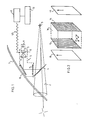
- the aerodyne has only been shown the canopy 1 through which the pilot can see the external environment.
- the pilot's field of vision 2 has been indicated from his eye 3.
- an optical mixer 4 constituted for example by a partially reflecting mirror forming part of a display device 5 such as a viewfinder and / or even a head-up flight director.
- This display device 5 consists of a focused and suitably cooled light source 6 which illuminates via a filter 7, for example an infrared filter, and / or a monochromatic filter, a liquid crystal matrix 8 placed in the object focal plane of an optical system successively comprising a first lens 9, a mirror 10 at 45 ° and a second lens 11 focused at right angles to the first.
- the optical system makes it possible to project on the partially reflecting mirror 4 the image of the liquid crystal matrix 8 which is superimposed in the field of vision 2 of the pilot, on his vision of the external environment.
- the liquid crystal matrix 8 is also connected, via a digital link 121, to an onboard computer of the aerodyne 12, which is located connected to various peripheral interfaces specific to the aerodyne (13).
- the liquid crystal matrix 8 consists of two parallel transparent glass plates 14,15 between which is disposed a layer of liquid crystal 16 (fig. 2).
- Each of these glass plates supports a network of addressable electrodes forming the rows and columns of the matrix, which can be connected by means of flexible connectors, to an electronic control circuit.
- the matrix further comprises two polarizers 17, 18 with parallel axes arranged on either side of the assembly formed by the two glass plates 14, 15 and of the liquid crystal layer 16, one of these polarizers playing the role of an analyzer.
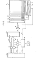
- each of the row and column electrodes is connected to an amplifier (driver) (blocks 20) intended to supply either a Von voltage for the ignition of a pixel, or a Voff voltage for the extinction of the pixel, these amplifiers being preferably adjusted so that the Von / Voff ratio is equal to 3 (FIG. 3).
- These amplifiers 20 are controlled from a buffer memory 21 (buffer), by means of the transfer control device 22 of the logic levels (bits) stored in the buffer memory 21 on the control electrodes of the amplifiers 20 (drivers).
- the symbol generator consists of an automaton controlled by a clock H which attacks a sequencing counter 23 provided for cyclically sending the content of a random access memory RAM 26, of capacity greater than k (n + m) bits on the buffer memories 21 associated with the liquid crystal cell 8, (k being the multiplexing coefficient, n and m being respectively the number of rows and columns of the liquid crystal matrix)
- This RAM memory 26 is connected by its starters Ao Vietnamese A15 to the BUS of the addresses of a computer 27 via a first selection circuit 28.
- the inputs Ao Vietnamese A15 of the RAM are connected to the output of the sequencer counter 23 via a second selection circuit 29.
- connection between the symbol generator and the central computer 27 also involves a command line 30 DIN (Data in) allowing the storage in the RAM 26 of the information coming from the central computer 27 (and its updating), a line 31 controlling the selection circuits 28, 29 so as to obtain addressing of the RAM 26 by the central computer 27 or by the sequencing counter 23 and a link 32 allowing the sequencing counter 23 to send a signal to the central computer 27 indicating the end of the display of an elementary image.
- DIN Data in
- the memory 26 is refreshed by the central computer 27 (Address bus 36, DIN line 30) during the bit transmission intervals, thanks to the selection circuits 28 and 29.
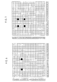
- FIG. 4 represents an example of image to be displayed on a liquid crystal matrix 8 comprising twenty rows and twenty columns. It should be noted that this limited number of rows and columns has been chosen solely for the clarity of the drawings. On this subject, it is recalled that the object of the invention, on the contrary, is the use of matrices having a much higher number of rows and columns, for example greater than 100 rows and greater than 100 columns so as to be able to obtain images presenting a relatively high definition.
- the image generated on the liquid crystal matrix comprises six symbols 40, 41, 42, 43, - 44, 45 formed by an adequate distribution of lit pixels which, in this example, have a square shape.
- the symbol 40 is obtained by means of eight pixels 46 to 53 dispersed around the circumference of a circle whose center is materialized by a pixel 54.
- the symbol 41 of rectangular shape involves two rows of three pixels juxtaposed one on the other.
- the symbol 43 has an L shape and comprises three pixels 56, 57, 58 juxtaposed on the same column and a pixel 60 on the same line as the pixel 58.
- the symbol 44 has a C shape comprising three pixels 61, 62, 63 juxtaposed on the same column and two pixels 64, 65 juxtaposed with pixels 61, 63 respectively on the same lines.
- the symbol 45 has a D shape of the type described above with, in addition, pixels 66 to 70, a pixel 71 arranged on the same line as the pixel 68, but offset by one pixel.
- the symbol 42 comprises a pattern 72 comprising ten pixels superimposed in the same column and a pattern 73 comprising six pixels superimposed in the next column.
- the decomposition of this image into independent elementary images is carried out by taking takes into account the sets of pixels whose simultaneous activations are compatible.
- the multiplexing rate should be at least 15.
- the multiplexing rate is reduced to 9.
Landscapes
- Engineering & Computer Science (AREA)
- Chemical & Material Sciences (AREA)
- Crystallography & Structural Chemistry (AREA)
- Physics & Mathematics (AREA)
- Computer Hardware Design (AREA)
- General Physics & Mathematics (AREA)
- Theoretical Computer Science (AREA)
- Control Of Indicators Other Than Cathode Ray Tubes (AREA)
- Liquid Crystal Display Device Control (AREA)
Applications Claiming Priority (2)
| Application Number | Priority Date | Filing Date | Title |
|---|---|---|---|
| FR8313698 | 1983-08-25 | ||
| FR8313698A FR2551245B1 (fr) | 1983-08-25 | 1983-08-25 | Procede et dispositif pour l'affichage de symboles a l'aide d'une matrice a cristaux liquides |
Publications (1)
| Publication Number | Publication Date |
|---|---|
| EP0142385A1 true EP0142385A1 (de) | 1985-05-22 |
Family
ID=9291796
Family Applications (1)
| Application Number | Title | Priority Date | Filing Date |
|---|---|---|---|
| EP84401656A Withdrawn EP0142385A1 (de) | 1983-08-25 | 1984-08-09 | Verfahren und Einrichtung zur Abbildung von Symbolen auf eine Flüssigkristallmatrixanzeige |
Country Status (3)
| Country | Link |
|---|---|
| US (1) | US4710766A (de) |
| EP (1) | EP0142385A1 (de) |
| FR (1) | FR2551245B1 (de) |
Families Citing this family (6)
| Publication number | Priority date | Publication date | Assignee | Title |
|---|---|---|---|---|
| DE69214206T2 (de) * | 1991-07-08 | 1997-03-13 | Asahi Glass Co. Ltd., Tokio/Tokyo | Steuerverfahren für ein Flüssigkristallanzeigeelement |
| US5793450A (en) * | 1994-11-10 | 1998-08-11 | Grumman Aerospace Corporation | Canopy transmittal reflectance control and information display |
| FR2757659B1 (fr) | 1996-12-20 | 1999-03-26 | Sextant Avionique | Procede d'optimisation de la detection du point d'attouchement d'une surface tactile capacitive |
| GB9907849D0 (en) * | 1999-04-06 | 1999-06-02 | Densitron Europ Limited | LCD control circuitry |
| JP2001195042A (ja) * | 2000-01-05 | 2001-07-19 | Internatl Business Mach Corp <Ibm> | 液晶パネル用ソース・ドライバ及びソース・ドライバ出力バラツキの平準化方法 |
| USD776133S1 (en) * | 2015-06-23 | 2017-01-10 | Zynga Inc. | Display screen or portion thereof with a graphical user interface |
Citations (2)
| Publication number | Priority date | Publication date | Assignee | Title |
|---|---|---|---|---|
| GB2037048A (en) * | 1978-12-04 | 1980-07-02 | Smith J | Liquid crystal game and training display apparatus |
| GB2079020A (en) * | 1980-05-30 | 1982-01-13 | Hughes Microelectronics Ltd | Method of generating input signals for subtractive combination |
Family Cites Families (12)
| Publication number | Priority date | Publication date | Assignee | Title |
|---|---|---|---|---|
| US3444319A (en) * | 1966-07-26 | 1969-05-13 | Rca Corp | Character generator |
| JPS5324140B2 (de) * | 1973-01-24 | 1978-07-19 | ||
| DE2344622A1 (de) * | 1973-09-05 | 1975-03-13 | Schenck Gmbh Carl | Unwuchtvektoranzeige mit fluessigkristallen |
| US3979793A (en) * | 1974-04-12 | 1976-09-14 | Barker International, Inc. | Poultry eviscerating apparatus |
| US3918041A (en) * | 1974-08-05 | 1975-11-04 | Roger A Mao | Multiplex display system |
| GB1577618A (en) * | 1976-12-03 | 1980-10-29 | Smiths Industries Ltd | Display systems |
| US4250503A (en) * | 1977-07-26 | 1981-02-10 | National Research Development Corporation | Apparatus for displaying waveforms on a matrix display |
| JPS5458399A (en) * | 1977-10-18 | 1979-05-11 | Sharp Corp | Matrix type liquid crystal display unit |
| US4190832A (en) * | 1978-04-18 | 1980-02-26 | Sailor Mohler | Polarized windshield indicia reflection display system |
| US4462027A (en) * | 1980-02-15 | 1984-07-24 | Texas Instruments Incorporated | System and method for improving the multiplexing capability of a liquid crystal display and providing temperature compensation therefor |
| US4370647A (en) * | 1980-02-15 | 1983-01-25 | Texas Instruments Incorporated | System and method of driving a multiplexed liquid crystal display by varying the frequency of the drive voltage signal |
| JPS56119192A (en) * | 1980-02-25 | 1981-09-18 | Sharp Kk | Method of driving liquid crystal matric display unit |
-
1983
- 1983-08-25 FR FR8313698A patent/FR2551245B1/fr not_active Expired
-
1984
- 1984-08-09 EP EP84401656A patent/EP0142385A1/de not_active Withdrawn
- 1984-08-21 US US06/642,815 patent/US4710766A/en not_active Expired - Fee Related
Patent Citations (2)
| Publication number | Priority date | Publication date | Assignee | Title |
|---|---|---|---|---|
| GB2037048A (en) * | 1978-12-04 | 1980-07-02 | Smith J | Liquid crystal game and training display apparatus |
| GB2079020A (en) * | 1980-05-30 | 1982-01-13 | Hughes Microelectronics Ltd | Method of generating input signals for subtractive combination |
Non-Patent Citations (1)
| Title |
|---|
| IBM TECHNICAL DISCLOSURE BULLETIN, vol. 22, no. 1, juin 1979, page 365, New York, USA; N.M. LEON: "Projected image display" * |
Also Published As
| Publication number | Publication date |
|---|---|
| FR2551245B1 (fr) | 1987-06-19 |
| FR2551245A1 (fr) | 1985-03-01 |
| US4710766A (en) | 1987-12-01 |
Similar Documents
| Publication | Publication Date | Title |
|---|---|---|
| EP0527084B1 (de) | Bildprojektor mit optimierter Lichtausbeute | |
| EP2082279A1 (de) | Optoelektronische anzeigenanordnung | |
| EP0305274B1 (de) | Verfahren und Vorrichtung zur Erzeugung von stereoskopischen Bildern | |
| FR2496949A1 (fr) | Dispositif electro-optique de commutation | |
| FR2542119A1 (fr) | Procede pour commander un ecran d'affichage matriciel a cristaux liquides | |
| EP0485268B1 (de) | Matrix-Bildprojektor mit zwei polarisierten Strahlen | |
| WO1999053355A1 (fr) | Microscope generant une representation tridimensionnelle d'un objet et images generees par ce microscope | |
| EP0055966A2 (de) | Matrixanzeigevorrichtung mit zwei Arten von Linienelektroden und Verfahren zu ihrer Ansteuerung | |
| FR2611389A1 (fr) | Dispositif imageur matriciel a cristaux liquides a resolution doublee par birefringence | |
| FR2922323A1 (fr) | Dispositif de surveillance croisee pour afficheurs dits tete haute | |
| EP0361992B1 (de) | Plasma-Anzeigeplatte mit modifizierter Adressierbarkeit | |
| FR2559923A1 (fr) | Systeme pour faire de la projection commentee de documents transparents ou de diapositives sur un ecran mural | |
| FR2794884A1 (fr) | Afficheur a cristaux liquides | |
| FR2499276A1 (fr) | Dispositif d'affichage matriciel a plusieurs jeux d'electrodes et son procede de commande | |
| EP0142385A1 (de) | Verfahren und Einrichtung zur Abbildung von Symbolen auf eine Flüssigkristallmatrixanzeige | |
| EP0540394B1 (de) | Binokulares Fernrohr mit doppeltem Bild | |
| EP2721598B1 (de) | Flüssigkristallanzeige mit löschelektroden | |
| FR2541027A1 (fr) | Imageur matriciel a dispositif de compensation du couplage entre les lignes et les colonnes | |
| EP0286529B1 (de) | Anordnung zur Bestimmung des Kontrastes eines Aufzeichnungsschirmes als Funktion der Beobachtungsrichtung | |
| FR2482811A1 (fr) | Enregistreur optoelectronique de telecopie | |
| FR2784489A1 (fr) | Procede d'affichage de donnees sur un afficheur matriciel | |
| EP1774505B1 (de) | Flüssigkristall-matrixanzeige | |
| EP0602218A1 (de) | Fluessigkristall-anzeige mit aktiver matrix | |
| EP0237539B1 (de) | Anlage zur steuerung einer matrixanzeigetafel mit integriertem speicher und verfahren zu deren steuerung | |
| EP0480813B1 (de) | Farbbildanzeigevorrichtung |
Legal Events
| Date | Code | Title | Description |
|---|---|---|---|
| PUAI | Public reference made under article 153(3) epc to a published international application that has entered the european phase |
Free format text: ORIGINAL CODE: 0009012 |
|
| AK | Designated contracting states |
Designated state(s): DE GB IT |
|
| 17P | Request for examination filed |
Effective date: 19850510 |
|
| 17Q | First examination report despatched |
Effective date: 19860811 |
|
| D17Q | First examination report despatched (deleted) | ||
| STAA | Information on the status of an ep patent application or granted ep patent |
Free format text: STATUS: THE APPLICATION IS DEEMED TO BE WITHDRAWN |
|
| 18D | Application deemed to be withdrawn |
Effective date: 19870910 |
|
| RIN1 | Information on inventor provided before grant (corrected) |
Inventor name: FAGARD, PIERRE Inventor name: DUBOIS, MARCEL |