EP0142392A2 - Vorrichtung zur Verbindung von Kabeln aus optischen Fasern - Google Patents
Vorrichtung zur Verbindung von Kabeln aus optischen Fasern Download PDFInfo
- Publication number
- EP0142392A2 EP0142392A2 EP84401773A EP84401773A EP0142392A2 EP 0142392 A2 EP0142392 A2 EP 0142392A2 EP 84401773 A EP84401773 A EP 84401773A EP 84401773 A EP84401773 A EP 84401773A EP 0142392 A2 EP0142392 A2 EP 0142392A2
- Authority
- EP
- European Patent Office
- Prior art keywords
- objective
- fibers
- cables
- fiber
- optical
- Prior art date
- Legal status (The legal status is an assumption and is not a legal conclusion. Google has not performed a legal analysis and makes no representation as to the accuracy of the status listed.)
- Withdrawn
Links
Images
Classifications
-
- G—PHYSICS
- G02—OPTICS
- G02B—OPTICAL ELEMENTS, SYSTEMS OR APPARATUS
- G02B6/00—Light guides; Structural details of arrangements comprising light guides and other optical elements, e.g. couplings
- G02B6/24—Coupling light guides
- G02B6/36—Mechanical coupling means
- G02B6/38—Mechanical coupling means having fibre to fibre mating means
- G02B6/3807—Dismountable connectors, i.e. comprising plugs
- G02B6/3873—Connectors using guide surfaces for aligning ferrule ends, e.g. tubes, sleeves, V-grooves, rods, pins, balls
- G02B6/3874—Connectors using guide surfaces for aligning ferrule ends, e.g. tubes, sleeves, V-grooves, rods, pins, balls using tubes, sleeves to align ferrules
- G02B6/3878—Connectors using guide surfaces for aligning ferrule ends, e.g. tubes, sleeves, V-grooves, rods, pins, balls using tubes, sleeves to align ferrules comprising a plurality of ferrules, branching and break-out means
-
- G—PHYSICS
- G02—OPTICS
- G02B—OPTICAL ELEMENTS, SYSTEMS OR APPARATUS
- G02B6/00—Light guides; Structural details of arrangements comprising light guides and other optical elements, e.g. couplings
- G02B6/24—Coupling light guides
- G02B6/26—Optical coupling means
- G02B6/32—Optical coupling means having lens focusing means positioned between opposed fibre ends
-
- G—PHYSICS
- G02—OPTICS
- G02B—OPTICAL ELEMENTS, SYSTEMS OR APPARATUS
- G02B6/00—Light guides; Structural details of arrangements comprising light guides and other optical elements, e.g. couplings
- G02B6/24—Coupling light guides
- G02B6/36—Mechanical coupling means
- G02B6/38—Mechanical coupling means having fibre to fibre mating means
- G02B6/3807—Dismountable connectors, i.e. comprising plugs
- G02B6/3833—Details of mounting fibres in ferrules; Assembly methods; Manufacture
- G02B6/3834—Means for centering or aligning the light guide within the ferrule
- G02B6/3838—Means for centering or aligning the light guide within the ferrule using grooves for light guides
- G02B6/3839—Means for centering or aligning the light guide within the ferrule using grooves for light guides for a plurality of light guides
Definitions
- the present invention relates to a device coupling, by an optical system, optical fiber cables together.
- This device can be used in particular as a connector for optical fiber cables.
- Devices for coupling two optical fibers or two optical fiber cables by means of an optical system formed by several separate objectives and arranged between said fibers whose ends are opposed.
- the variations of the focal lengths of these objectives cause losses on coupling of the fibers.
- the aim of the present invention is to overcome the drawbacks of the known devices from the point of view of focal length variations and to minimize the losses of flux on coupling by canceling them theoretically. It provides a device which ensures the simultaneous coupling of the fibers of one cable with the fibers of the other cable by conjugating any fiber of one to a fiber of the other.
- the design of the optical coupling system is very simple and allows all the optical fiber cables to be placed on the same side of this system.
- the device according to the invention couples optical fiber cables through an optical system comprising a converging objective and it is characterized in that the fibers of the cables are arranged so that their ends are located in the same side of said objective being directed towards the latter and in that the optical system comprises a fixed reflector, located on the other side of the cables by rap - port to the objective lens so that light rays from a fiber transmitting, after passing through the objective are reflected to said objections if t who focuses on the optical fiber coupled.
- the ends of the fibers of the cables are substantially located in a focal plane of the objective and the reflecting surface of the reflector is substantially situated in the other focal plane of said objective.
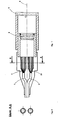
- the device couples two cables 1 and 2 which each group a plurality of optical fibers marked 11 and 21 respectively.
- Cables 1 and 2 are located on the same side of the optical coupling system.
- the latter is constituted by a converging objective 3 and by a reflector 4.
- the objective 3 preferably comprises at least two lenses.
- the reflector 4, of the mirror type, is located on the other side of the fibers relative to the objective 3. It receives the light signals at the exit of the objective and reflects them on said objective. It is fixedly mounted with respect to the fiber lens and to the housing containing the lens and the reflector.
- the mirror 4 is separated from the objective 3 by an air gap which is equal to the focal distance of the objective.
- the planar reflecting surface of the mirror 4 is located in the focal plane of the objective 3. It is perpendicular to the optical axis 5.
- the optical fibers 11 and 21 are parallel to the optical axis 5, their ends being directed towards the objective. These fiber ends are located in the focal plane of the objective which is symmetrical with the focal plane situated at the level of the mirror. They are arranged so that one fiber end is symmetrical with another fiber end, with respect to the optical axis.
- the ends of the two optical cables are fixed on two separate and disconnectable parts which allows the production of a connector.
- the ends of the fibers of each cable can be arranged according to generatrices of a grooved cylinder, the two cylinders being symmetrical with respect to the optical axis.
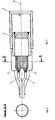
- the ends of the optical fibers are fixed to a part integral with the housing of the device.
- the ends of the fibers can be arranged according to generatrices of a grooved cylinder centered on the optical axis.
- the fibers 11 and 21 and the objective 3 are separated by an air gap.
- the fibers 11 and 21 could be glued to a glass block separate from the objective.
- the device for rait include a glass block making the junction between the ends of the fibers 11 and 21 and the face of the objective located on the side of these fibers, this glass block being glued to said ends and to said face.
- the reflector 4 is fixed in operation, it is possible to provide means for adjusting its orientation to optimize the coupling of the cables.
- the fibers 11 of the cable 1 are transmitting, simultaneously or not, and that the fibers 21 of the cable 2 are receiving.
- the signal or light beam coming from any emission fiber, after passing through the objective 3, is reflected by the mirror 4 towards the objective 3 which focuses it on a receiving fiber.
- the ends of the two fibers thus conjugated are symmetrical with respect to the optical axis.
- the flux emitted by a point on the exit surface of a transmitting fiber is located in a cone whose axis is normal to said surface.
- the receiving fiber transmits only rays arriving in a cone whose axis is normal to the entry surface of this fiber. Because the reflecting surface of the mirror 4 is contained in the focal plane of the objective, all the axes of the cones of light emitted by the light points of the exit surface of a transmitting fiber arrive perpendicularly: the entry surface of the receiving fiber.
- the optical device described constitutes a telecentric system such that the entrance pupil and the exit pupil are rejected ad infinitum, the intermediate pupil being situated in the focal plane of the objective therefore on the reflecting surface of the mirror.
- Optimal coupling is obtained when the ends of the optical fibers 11, 21 are located in the object focal plane of the objective and when the reflecting surface of the mirror is situated in the image focal plane of said objective. If the coincidence of the reflecting surface with the image focal plane and if the positioning of the ends of the fibers in the object focal plane are not performed within a few percent, the coupling losses become significant and the coupling is no longer admissible.
Landscapes
- Physics & Mathematics (AREA)
- General Physics & Mathematics (AREA)
- Optics & Photonics (AREA)
- Optical Couplings Of Light Guides (AREA)
Applications Claiming Priority (2)
| Application Number | Priority Date | Filing Date | Title |
|---|---|---|---|
| FR8314379A FR2551887B1 (fr) | 1983-09-09 | 1983-09-09 | Dispositif de couplage de cables de fibres optiques |
| FR8314379 | 1983-09-09 |
Publications (2)
| Publication Number | Publication Date |
|---|---|
| EP0142392A2 true EP0142392A2 (de) | 1985-05-22 |
| EP0142392A3 EP0142392A3 (de) | 1987-01-21 |
Family
ID=9292090
Family Applications (1)
| Application Number | Title | Priority Date | Filing Date |
|---|---|---|---|
| EP84401773A Withdrawn EP0142392A3 (de) | 1983-09-09 | 1984-09-07 | Vorrichtung zur Verbindung von Kabeln aus optischen Fasern |
Country Status (3)
| Country | Link |
|---|---|
| EP (1) | EP0142392A3 (de) |
| JP (1) | JPS60149014A (de) |
| FR (1) | FR2551887B1 (de) |
Cited By (1)
| Publication number | Priority date | Publication date | Assignee | Title |
|---|---|---|---|---|
| DE19506675A1 (de) * | 1995-02-25 | 1996-08-29 | Schumacher Hamedat Ursula Dr | Vorrichtung zur Einkopplung von durch eine Probe transmittiertem oder von einer Probe reflektiertem, gestreutem, emittiertem oder reemittiertem Licht in einen Lichtleiter |
Families Citing this family (1)
| Publication number | Priority date | Publication date | Assignee | Title |
|---|---|---|---|---|
| US4729619A (en) * | 1986-05-01 | 1988-03-08 | Minnesota Mining And Manufacturing Company | Optical fiber connector incorporating means for isolating connection from external stresses |
Family Cites Families (6)
| Publication number | Priority date | Publication date | Assignee | Title |
|---|---|---|---|---|
| DE2522740C3 (de) * | 1975-05-22 | 1981-05-14 | Siemens AG, 1000 Berlin und 8000 München | Vorrichtung zum Verbinden eines ankommenden Lichtleitfaserkabels mit einem weiterführenden und Verfahren zur Herstellung der Vorrichtung |
| GB1549186A (en) * | 1975-10-03 | 1979-08-01 | Nat Res Dev | Optical connectors |
| GB2029046B (en) * | 1978-08-31 | 1982-11-17 | Bunker Ramo | Distributive couplers for fibre optics |
| JPS5853322B2 (ja) * | 1980-05-12 | 1983-11-29 | 日本電信電話株式会社 | 小形集光器 |
| JPS5772120A (en) * | 1980-10-24 | 1982-05-06 | Nippon Telegr & Teleph Corp <Ntt> | Optical branching filter |
| EP0062429A1 (de) * | 1981-04-04 | 1982-10-13 | Plessey Overseas Limited | Optische Kupplungsvorrichtungen für optische Fasern |
-
1983
- 1983-09-09 FR FR8314379A patent/FR2551887B1/fr not_active Expired
-
1984
- 1984-09-07 JP JP18787684A patent/JPS60149014A/ja active Pending
- 1984-09-07 EP EP84401773A patent/EP0142392A3/de not_active Withdrawn
Cited By (2)
| Publication number | Priority date | Publication date | Assignee | Title |
|---|---|---|---|---|
| DE19506675A1 (de) * | 1995-02-25 | 1996-08-29 | Schumacher Hamedat Ursula Dr | Vorrichtung zur Einkopplung von durch eine Probe transmittiertem oder von einer Probe reflektiertem, gestreutem, emittiertem oder reemittiertem Licht in einen Lichtleiter |
| DE19506675C2 (de) * | 1995-02-25 | 1999-08-19 | Schumacher Hamedat | Vorrichtung zur Einkopplung von durch eine Probe transmittiertem oder von einer Probe reflektiertem, gestreutem, emittiertem oder reemittiertem Licht in einen Lichtleiter |
Also Published As
| Publication number | Publication date |
|---|---|
| FR2551887B1 (fr) | 1987-02-20 |
| EP0142392A3 (de) | 1987-01-21 |
| FR2551887A1 (fr) | 1985-03-15 |
| JPS60149014A (ja) | 1985-08-06 |
Similar Documents
| Publication | Publication Date | Title |
|---|---|---|
| EP0121482B1 (de) | Wellenlängenmultiplexer/-demultiplexer und Verfahren zur Herstellung einer solchen Vorrichtung | |
| EP0275795A1 (de) | Wellenlängen-Multiplexer/-Demultiplexer mit einem elliptischen Konkavgitter und dessen Anwendung in der integrierten Optik | |
| FR2461966A1 (fr) | Accouplement demontable permettant le couplage d'une paire de fibres photoconductrices | |
| FR2521751A1 (fr) | Dispositif pour la transmission de signaux entre parties pouvant tourner l'une par rapport a l'autre | |
| EP0138698A2 (de) | Optischer Wellenlängen-Multiplexer-Demultiplexer für bidirektionale Verbindung | |
| CA1250465A (fr) | Commutateur pour circuit a guide de lumiere | |
| FR2608785A1 (fr) | Dispositif de connexion de fibres optiques a un circuit optique integre et procede de realisation | |
| US5838859A (en) | Bidirectional optical transceiver assembly | |
| EP0282766A1 (de) | Aktives optisches Steckergehäuse | |
| EP0102264B1 (de) | Anordnung zur Wellenlängen Multiplexierung oder Demultiplexierung mit optischer Trennung | |
| EP0072840A1 (de) | Verfahren zum multiplexen von übertragungskanälen in einer optischen faser mit stufen-index und vorrichtung zur durchführung des verfahrens. | |
| FR2488455A1 (fr) | Dispositif muni d'une diode laser semi-conductrice | |
| EP0018873B1 (de) | Kompakte optische Koppelungsvorrichtung und solch eine Vorrichtung enthaltender interferometrischer Gyrometer mit einer optischen Faser | |
| EP0064919B1 (de) | Vorrichtung zur Ein- und/oder Ausgabe eines optischen Signals | |
| FR2834565A1 (fr) | Dispositif pour faire entrer des signaux optiques dans un guide d'ondes de lumiere et/ou pour les en faire sortir | |
| FR2542461A1 (fr) | Dispositif optique de multiplexage demultiplexage | |
| EP0142392A2 (de) | Vorrichtung zur Verbindung von Kabeln aus optischen Fasern | |
| FR2670577A1 (fr) | Dispositif d'analyse de capteurs interferometriques de micro-deplacements. | |
| FR2526961A1 (fr) | Dispositif pour connecter un generateur de rayonnement optique et un guide d'onde optique | |
| FR2661513A3 (fr) | Aiguillage optique a fibres. | |
| EP0153243A1 (de) | Faseroptisches Schaltgerät | |
| EP0633424B1 (de) | Faseroptische Lichtquelleneinrichtung mit verstellbarem Lichtbündel | |
| EP0142393A2 (de) | Vorrichtung zur Verbindung von Kablen aus optischen Fasern | |
| FR2548793A1 (fr) | Coupleur optique pour relier des fibres optiques | |
| FR2556480A1 (fr) | Coupleur bidirectionnel optique actif |
Legal Events
| Date | Code | Title | Description |
|---|---|---|---|
| PUAI | Public reference made under article 153(3) epc to a published international application that has entered the european phase |
Free format text: ORIGINAL CODE: 0009012 |
|
| AK | Designated contracting states |
Designated state(s): AT BE CH DE FR GB IT LI LU NL SE |
|
| PUAL | Search report despatched |
Free format text: ORIGINAL CODE: 0009013 |
|
| AK | Designated contracting states |
Kind code of ref document: A3 Designated state(s): AT BE CH DE FR GB IT LI LU NL SE |
|
| 17P | Request for examination filed |
Effective date: 19870205 |
|
| 17Q | First examination report despatched |
Effective date: 19881216 |
|
| STAA | Information on the status of an ep patent application or granted ep patent |
Free format text: STATUS: THE APPLICATION IS DEEMED TO BE WITHDRAWN |
|
| 18D | Application deemed to be withdrawn |
Effective date: 19900203 |
|
| RIN1 | Information on inventor provided before grant (corrected) |
Inventor name: BALUTEAU, JEAN-MICHEL Inventor name: MOIREZ, JACQUES Inventor name: SAINT-SEVIN, MICHEL Inventor name: SELLIN, REMY Inventor name: FILLOL, BERNARD |