EP0142401A1 - Vorrichtung zum Senden von numerischen Daten und Anwendung insbesondere bei Wiederholungszählern - Google Patents
Vorrichtung zum Senden von numerischen Daten und Anwendung insbesondere bei Wiederholungszählern Download PDFInfo
- Publication number
- EP0142401A1 EP0142401A1 EP84401926A EP84401926A EP0142401A1 EP 0142401 A1 EP0142401 A1 EP 0142401A1 EP 84401926 A EP84401926 A EP 84401926A EP 84401926 A EP84401926 A EP 84401926A EP 0142401 A1 EP0142401 A1 EP 0142401A1
- Authority
- EP
- European Patent Office
- Prior art keywords
- spring
- signal
- arming
- counter
- triggering
- Prior art date
- Legal status (The legal status is an assumption and is not a legal conclusion. Google has not performed a legal analysis and makes no representation as to the accuracy of the status listed.)
- Granted
Links
- 230000005540 biological transmission Effects 0.000 title claims abstract description 7
- 230000007246 mechanism Effects 0.000 claims abstract description 25
- 230000011664 signaling Effects 0.000 claims abstract description 16
- 239000012530 fluid Substances 0.000 claims abstract description 13
- 230000009467 reduction Effects 0.000 claims abstract description 5
- 239000007788 liquid Substances 0.000 claims abstract description 3
- 238000000034 method Methods 0.000 claims description 4
- 230000008569 process Effects 0.000 claims description 4
- 230000001360 synchronised effect Effects 0.000 claims description 4
- 230000001960 triggered effect Effects 0.000 claims description 4
- 230000006835 compression Effects 0.000 claims description 2
- 238000007906 compression Methods 0.000 claims description 2
- 238000004146 energy storage Methods 0.000 claims description 2
- 230000003287 optical effect Effects 0.000 claims description 2
- 238000006073 displacement reaction Methods 0.000 claims 1
- 230000008054 signal transmission Effects 0.000 claims 1
- 238000009434 installation Methods 0.000 description 8
- 238000010586 diagram Methods 0.000 description 4
- 239000013307 optical fiber Substances 0.000 description 4
- 238000013016 damping Methods 0.000 description 3
- 230000008901 benefit Effects 0.000 description 2
- 230000000903 blocking effect Effects 0.000 description 2
- 239000010453 quartz Substances 0.000 description 2
- VYPSYNLAJGMNEJ-UHFFFAOYSA-N silicon dioxide Inorganic materials O=[Si]=O VYPSYNLAJGMNEJ-UHFFFAOYSA-N 0.000 description 2
- 238000004804 winding Methods 0.000 description 2
- WHXSMMKQMYFTQS-UHFFFAOYSA-N Lithium Chemical compound [Li] WHXSMMKQMYFTQS-UHFFFAOYSA-N 0.000 description 1
- 230000015556 catabolic process Effects 0.000 description 1
- 230000006866 deterioration Effects 0.000 description 1
- 239000000835 fiber Substances 0.000 description 1
- 238000002513 implantation Methods 0.000 description 1
- 238000003780 insertion Methods 0.000 description 1
- 230000037431 insertion Effects 0.000 description 1
- 229910052744 lithium Inorganic materials 0.000 description 1
- 238000005259 measurement Methods 0.000 description 1
- 230000001681 protective effect Effects 0.000 description 1
- 230000000717 retained effect Effects 0.000 description 1
- 239000000126 substance Substances 0.000 description 1
Images


Classifications
-
- G—PHYSICS
- G01—MEASURING; TESTING
- G01F—MEASURING VOLUME, VOLUME FLOW, MASS FLOW OR LIQUID LEVEL; METERING BY VOLUME
- G01F15/00—Details of, or accessories for, apparatus of groups G01F1/00 - G01F13/00 insofar as such details or appliances are not adapted to particular types of such apparatus
- G01F15/06—Indicating or recording devices
- G01F15/061—Indicating or recording devices for remote indication
- G01F15/063—Indicating or recording devices for remote indication using electrical means
Definitions
- the subject of the invention is a device making it possible to transmit digital information remotely provided by a meter for measuring the flow of a liquid or gaseous fluid.
- the invention relates to the remote repetition of the information carried by a main totalizing counter.
- the invention finds its application in particular in the familiar field of energy meters such as gas meters which, in particular for old installations, are located at the subscriber's. This situation of the meter at the subscriber creates a constraint on the meter reading.
- the invention makes it possible to remove this constraint by the fact that it will be possible easily and inexpensively to install a repeater at a suitable distance from the main meter, which repeater will be able, without requiring its own power supply, to repeat the indications of the main meter. in an appropriate location for the reading, for example in an external table for grouping all the meters in the same building.
- the implementation of the invention does not require the supply of power supply specific to the operation of the repeater, and allows the transmission of information by flexible cables of the electrical or optical fiber type, it appears that the applications can be very diverse, and are particularly well suited each When the working conditions are delicate, for example if it is the reading of the flow of a combustible gas or even if it is a reading in a dangerous zone (refineries, mines, ...) or in contaminated or difficult to access areas (chemical, nuclear industry, etc.).
- the remote transmission being done by a cable or a flexible pipe of electrical, optical or hydraulic type, it will be possible in practice to transmit and repeat the desired information at a distance quite sufficient to allow the recording of these information in the accessibility and security conditions sought.
- the device according to the invention is characterized for this purpose in that it comprises a signaling device capable, when armed, of emitting a signal, said signaling device being armed with energy taken from the fluid flow, and said signal being used in any suitable signaling output device such as a repeater.
- the arming energy of the device is taken mechanically from the drive mechanism of the counter totalizing wheels.
- the device is mechanically armed from a little energy taken from the fluid flow, and when the energy-stored is sufficient, the device can emit a signal of appropriate quality such as a voltage signal electric, a hydraulic pressure signal, etc. which can be easily conveyed to the repeater located at a distance from the meter, the supply of signals making it possible to transmit information from the meter to the repeater.
- the emission of the signal is controlled and triggered after arming the signaling device by the meter display device.
- the meter display device For example, if it is a gas meter, a signal can be emitted after display by the meter of each newly totaled m 3 .
- the emission of the signal and the arming of the device are synchronized so that the emission occurs only at a determined phase of the cycle after the arming process, so that it does not occur of interference in these two functions.
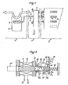
- FIG. 1 illustrates an installation essentially comprising a main counter 1 generating digital type information, a grouping box 2 of repeaters or totalizers which can be placed at a distance from the various counters 1, and at 3, the wire connection device or flexible cables connecting the various counters 1 to the grouping box 2.
- the device 3 will advantageously further comprise a device 4 for detecting failure or fraud which may be fixed or possibly mobile by providing a socket, for example of the "jack" type "5 on the connecting wires such as 6, assuming in this case, that these wires are of electrical types and conduct electrical signals.
- a mobile device it is possible, for example, to use a portable device for putting the counter and the repeater at the same index, device of a type known per se which can be connected to the connection circuit 6, at the place of socket 5.
- This device can resemble signaling “tops” at a very rapid rate so that, after a breakdown or when the device is started, put the repeater 10 to the same index as that displayed at 9 on the main counter 8.
- the counter or counters for example count the flow of a fluid shown diagrammatically by the arrow 7 passing through the housing 8 of the counter, this flow causing the various decimal drums of the counter totalizer which have been suggested at 9.
- energy is taken from the drum drive system 9 to transmit an information signal which will be transmitted by the link 6 to the corresponding repeater, for example as marked 10, in the grouping box. 2 by wires a and b.
- the latter controls in a manner known per se a fault signal such as a flag 11 then appearing next to the repeater 104
- the flag 11 switch signal is conveyed by the third wire c from the device 4 and the common wire b.
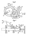
- the signaling device comprises a plunger 12 mechanically guided in the frame 13 of a solenoid 14 at the terminals 15 and 16 from which the voltage signal generated by the system will be collected.
- the plunger 12 can be cocked as will be described by being pushed in the direction of the arrow 17 against a spring 18 of an appropriate type making it possible to store the energy necessary for the emission of a signal electric of sufficient quality.
- the spring 18 has been represented diagrammatically as a helical compression spring, it may however be of any other type, for example with stackable elastic washers, pneumatic or other.
- a disc 19 is used carrying a cocking finger 20 which pushes the enlarged head 12a of the plunger 12 against the cocking spring 18.
- the disc 19 and the finger 20 therefore act in the manner of a cam allowing the arming of the device, this cam possibly being of a shape adapted to the particular mounting system on which it is mounted.
- the disc 19 is driven by means of two return pinions 21, 22 ensuring a suitable reduction in force by the motor pinion 23 driving the totalizer counter 9.
- the chain of successive sprockets 23, 22, 24, 25, 26, 27 driving the wheel 28 of the counter units for example liters of gas or other measured by the counter 9.
- This signal is used by being applied for example to a flexible electric line 6 to control the corresponding drive of a notch of the associated repeater counter 10.
- the electrical signal generated in this case is not very important, the voltage collected being proportional to the magnetic field of the magnet, to the number of turns of the solenoid 14 and to the speed of insertion of the core into the solenoid.
- This voltage is sufficient to in practice allow the driving of an electromechanical repeater counter with low control energy.
- the advantage of the system thus designed is that it can easily equip a conventional counter, for example of the domestic gas type, by being housed under the protective cover of the display device.
- the device for generating the pulse signal described above consisting of a plunger magnet introduced into the axis of a solenoid, is replaced by a device of the dynamo type making it possible to generate a voltage signal of longer duration and greater energy.
- a spiral spring 39 for example of the leaf type, one end of which is anchored at 40 on the axis 38 and the other end is anchored at 41 on a frame 42, to which the dynamo 37 is also fixed.
- the current outputs of the dynamo are shown.
- the device can be armed, as shown diagrammatically in FIG. 6, again using as driving energy that of the pinion 23 for driving the totalizer to be equipped.
- the pinion 23 meshes with a multiplier pinion 43 which drives an intermediate pinion 44 fixed on the same axis, which meshes with a pinion 45 integral with the axis 46 of winding of the spring 39.
- the end 41 .du spring 39 is anchored on the cage 47, free to rotate on the axis 46, and which while protecting the spring externally carries ratchet teeth 48 allowing during this reassembly of the springunidirectional blocking of the cage.
- the cage 47 also carries a toothing 50 which meshes with a pinion 51 linked to the axis 38 of the dynamo 37.
- a pinion 51 linked to the axis 38 of the dynamo 37.
- a signal is generated each time the pawl 49 releases the ratchet wheel 48 when it is tilted around the axis 53 by the cam 54 of the cam wheel 55 which will, as in the embodiment described above, be controlled in synchronism by the wheel of the counter of the desired floor, either the wheel of cubic meters or hundreds of liters for example, if it is a gas meter.
- a freewheel mechanism (not shown) is advantageously provided between the axis 38 and the pinion 51 to avoid too great a stress on the mechanism due to the inertia of the rotor of the dynamo 37 at the end of the unwinding of the spring 39.
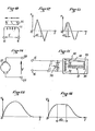
- the voltage signal supplied by such a dynamo is of greater power than that supplied by the solenoid, and its shape is illustrated in FIG. 15, as will be described below.
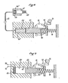
- a spring 62 for end-of-travel damping will advantageously be provided of the plunger to avoid impact of the piston on the frame 13.
- the spring will also have the advantage of damping the operating noise of the system.
- a similar damping spring 62 will also advantageously be provided in the case of FIG. 7.
- the electrical energy supplied by the dynamo will make it possible to control the operation of a repeater which may be of the conventional electromechanical type, the control energy this time being sufficient.
- the signal generated is of the electrical type.
- the invention is not however limited to the generation of such signals.
- FIG. 8 there is an installation comprising a plunger 63 guided in a cylinder 64 and which is capable of being armed against a spring 18 by means of a finger wheel 19 arming 20, the device being able to be triggered by a pawl 32 controlled by a triggering cam 35.
- the piston 63 does not act inside a solenoid, but inside a cylinder 64 filled with a suitable pressure transmission fluid enclosed in an elastic chamber with a corrugated wall 64 'which allows to remotely return this pressure via a pipe 65 which is advantageously flexible but not expandable, linked to the volume of an elastic sleeve 66 ′ placed in a receiving cylinder 66 in which the piston 67 constituting the member moves of. signal reception.
- a weak return spring has been shown diagrammatically which can be used to facilitate the return of the system to the cocking position illustrated in solid lines in the figure.
- FIG. 10 there is illustrated the magnet 36 moving relative to the solenoid 14 and the voltage induced at the terminals 15, 16 of the solenoid.
- This voltage can be used in an assembly of the type illustrated in FIG. 11 to come and drive the armature 72 of a solenoid 73 in order to actuate it at each voltage pulse.
- the frame controls the tilting of a lever 81 around an axis 82, which lever, by a ratchet 83 and a ratchet wheel 84 controls the passage of a notch of the unitary wheel of the repeater counter 10 including the wheel 84 is united.
- Zener diodes 74 which will make it possible to clip the voltage.
- FIG. 12 we see the simplified form of the signal transmitted without clipping by the Zener diodes, either that such diodes are not used, or that the signal does not have sufficient power, and in FIG. 13, the same signal is seen after clipping, the duration of the clipping being limited to ⁇ t1.
- FIG. 14 the dynamo 37 and the voltage V produced at its terminals 58, 59 are shown diagrammatically.
- FIG. 17 a variant has been illustrated in which the signal of voltage E or of electromotive force V produced at the terminals of the solenoid 14 or of the dynamo 37 was used to power a light-emitting diode 75 which is coupled to an optical fiber 76 to one of its ends 77, while the other end 78 of the optical fiber is coupled to a photocoupler 79 which generates an electrical signal used for driving the repeater counter 10.
- the meter is advantageously a low-consumption electronic meter with integrated long-life lithium battery (shown diagrammatically in 80).
- the applications of the device can relate to very diverse fields and find application whenever it is advantageous to repeat at a certain distance information given in one place by a type of counter with digital display and independently of the identity of the fluid on which the measurement is made.
Landscapes
- Physics & Mathematics (AREA)
- Fluid Mechanics (AREA)
- General Physics & Mathematics (AREA)
- Arrangements For Transmission Of Measured Signals (AREA)
- Dc Digital Transmission (AREA)
Priority Applications (1)
| Application Number | Priority Date | Filing Date | Title |
|---|---|---|---|
| AT84401926T ATE38719T1 (de) | 1983-09-28 | 1984-09-26 | Vorrichtung zum senden von numerischen daten und anwendung insbesondere bei wiederholungszaehlern. |
Applications Claiming Priority (2)
| Application Number | Priority Date | Filing Date | Title |
|---|---|---|---|
| FR8315397A FR2552543B1 (fr) | 1983-09-28 | 1983-09-28 | Dispositif permettant de transmettre a distance une information de type numerique et application notamment aux compteurs repetiteurs |
| FR8315397 | 1983-09-28 |
Publications (2)
| Publication Number | Publication Date |
|---|---|
| EP0142401A1 true EP0142401A1 (de) | 1985-05-22 |
| EP0142401B1 EP0142401B1 (de) | 1988-11-17 |
Family
ID=9292606
Family Applications (1)
| Application Number | Title | Priority Date | Filing Date |
|---|---|---|---|
| EP84401926A Expired EP0142401B1 (de) | 1983-09-28 | 1984-09-26 | Vorrichtung zum Senden von numerischen Daten und Anwendung insbesondere bei Wiederholungszählern |
Country Status (4)
| Country | Link |
|---|---|
| EP (1) | EP0142401B1 (de) |
| AT (1) | ATE38719T1 (de) |
| DE (1) | DE3475222D1 (de) |
| FR (1) | FR2552543B1 (de) |
Cited By (3)
| Publication number | Priority date | Publication date | Assignee | Title |
|---|---|---|---|---|
| FR2647206A1 (fr) * | 1989-05-19 | 1990-11-23 | Sauter Ag | Perfectionnements aux dispositifs de lecture des compteurs a gaz |
| CN108180958A (zh) * | 2018-03-01 | 2018-06-19 | 北京优耐燃气仪表有限公司 | 一种燃气表计数机构及燃气表 |
| CN112703538A (zh) * | 2018-12-12 | 2021-04-23 | 株式会社东芝 | 读取辅助系统、移动体、读取辅助方法、程序以及存储介质 |
Families Citing this family (2)
| Publication number | Priority date | Publication date | Assignee | Title |
|---|---|---|---|---|
| ES2011576A6 (es) * | 1989-05-16 | 1990-01-16 | Compania Para La Fabricacion D | Sistema para telelectura y telecorte de contadores de gas domesticos. |
| FR2740825B1 (fr) | 1995-11-03 | 1998-01-23 | Somfy | Installation de commande d'elements de protection solaire |
Citations (4)
| Publication number | Priority date | Publication date | Assignee | Title |
|---|---|---|---|---|
| US3039311A (en) * | 1959-06-23 | 1962-06-19 | American Meter Co | Water meter |
| US3555902A (en) * | 1968-03-09 | 1971-01-19 | Kimmon Mfg Co Ltd | Flow meter |
| US3731533A (en) * | 1969-10-16 | 1973-05-08 | Dresser Ind | Electrical generator having non-salient poles for metering shaft rotation of a turbine assembly |
| US4032805A (en) * | 1975-09-18 | 1977-06-28 | Gamon-Calmet Industries, Inc. | Electrical pulse generator for remote reading meter |
-
1983
- 1983-09-28 FR FR8315397A patent/FR2552543B1/fr not_active Expired
-
1984
- 1984-09-26 EP EP84401926A patent/EP0142401B1/de not_active Expired
- 1984-09-26 DE DE8484401926T patent/DE3475222D1/de not_active Expired
- 1984-09-26 AT AT84401926T patent/ATE38719T1/de not_active IP Right Cessation
Patent Citations (4)
| Publication number | Priority date | Publication date | Assignee | Title |
|---|---|---|---|---|
| US3039311A (en) * | 1959-06-23 | 1962-06-19 | American Meter Co | Water meter |
| US3555902A (en) * | 1968-03-09 | 1971-01-19 | Kimmon Mfg Co Ltd | Flow meter |
| US3731533A (en) * | 1969-10-16 | 1973-05-08 | Dresser Ind | Electrical generator having non-salient poles for metering shaft rotation of a turbine assembly |
| US4032805A (en) * | 1975-09-18 | 1977-06-28 | Gamon-Calmet Industries, Inc. | Electrical pulse generator for remote reading meter |
Cited By (5)
| Publication number | Priority date | Publication date | Assignee | Title |
|---|---|---|---|---|
| FR2647206A1 (fr) * | 1989-05-19 | 1990-11-23 | Sauter Ag | Perfectionnements aux dispositifs de lecture des compteurs a gaz |
| CN108180958A (zh) * | 2018-03-01 | 2018-06-19 | 北京优耐燃气仪表有限公司 | 一种燃气表计数机构及燃气表 |
| CN108180958B (zh) * | 2018-03-01 | 2023-12-01 | 北京优耐燃气仪表有限公司 | 一种燃气表计数机构及燃气表 |
| CN112703538A (zh) * | 2018-12-12 | 2021-04-23 | 株式会社东芝 | 读取辅助系统、移动体、读取辅助方法、程序以及存储介质 |
| CN112703538B (zh) * | 2018-12-12 | 2023-06-30 | 株式会社东芝 | 读取辅助系统、移动体、读取辅助方法、程序以及存储介质 |
Also Published As
| Publication number | Publication date |
|---|---|
| FR2552543A1 (fr) | 1985-03-29 |
| EP0142401B1 (de) | 1988-11-17 |
| DE3475222D1 (en) | 1988-12-22 |
| ATE38719T1 (de) | 1988-12-15 |
| FR2552543B1 (fr) | 1986-10-10 |
Similar Documents
| Publication | Publication Date | Title |
|---|---|---|
| EP0142401B1 (de) | Vorrichtung zum Senden von numerischen Daten und Anwendung insbesondere bei Wiederholungszählern | |
| FR2459961A1 (fr) | Generateur de signaux de distance parcourue pour vehicules | |
| WO2021123176A1 (fr) | Actionneur électromécanique pour dispositif d'occultation ou de protection solaire et installation d'occultation ou de protection solaire comprenant un tel actionneur | |
| EP2193070A2 (de) | Unterwasserboje | |
| FR2485153A1 (fr) | Detecteur optique de positionnement de vanne | |
| FR2698656A1 (fr) | Perfectionnements aux dispositifs pour détecter la position engagée d'un pêne. | |
| EP0482162A1 (de) | Betätigungsvorrichtung für die verzögerte auslösung eines mechanismus. | |
| FR2672410A1 (fr) | Dispositif de surveillance et de protection anti-vol. | |
| FR2499294A1 (fr) | Procede et dispositif de surveillance des barres de controles d'un reacteur nucleaire | |
| FR2486278A1 (fr) | Couple de cellules photoelectriques a rayons infrarouges notamment pour la commande d'un element de puissance | |
| FR2482730A1 (fr) | Dispositif de mesure de la frequence d'un courant electrique representative d'une grandeur variable | |
| WO1993003339A1 (fr) | Jaugeur de niveau pour reservoir de type a palpeur asservi | |
| EP0100387A1 (de) | Optische Anlagen für Annäherungsdetektoren | |
| FR2878062A1 (fr) | Procede et dispositif de declenchement manuel | |
| EP1493987B1 (de) | Rotierender, Lichtimpulse aussendender Flugkörper | |
| FR2666163A1 (fr) | Dispositif opto-electronique de detection de fumees ou de gaz en suspension dans l'air. | |
| EP1119740A1 (de) | Magnetooptische entfernungsmessvorrichtung und messeinrichtung mit dieser vorrichtung | |
| FR2647206A1 (fr) | Perfectionnements aux dispositifs de lecture des compteurs a gaz | |
| FR2504684A1 (fr) | Perfectionnements aux dispositifs optiques de detection de proximite | |
| FR3167374A1 (fr) | Système d’aide à la récupération d’au moins un objet immergé | |
| EP3023562A1 (de) | Türbewegungsvorrichtung mit elektrischer blockierung | |
| FR2565720A1 (fr) | Systeme de collecte de donnees en provenance de machines a affranchir | |
| BE428618A (de) | ||
| FR2670575A1 (fr) | Dispositif d'occultation des cibles de "tir a air comprime", permettant la pratique du "tir de vitesse". | |
| EP0049202A1 (de) | Elektronisches System zur Selbstkontrolle |
Legal Events
| Date | Code | Title | Description |
|---|---|---|---|
| PUAI | Public reference made under article 153(3) epc to a published international application that has entered the european phase |
Free format text: ORIGINAL CODE: 0009012 |
|
| AK | Designated contracting states |
Designated state(s): AT BE CH DE GB IT LI LU NL SE |
|
| 17P | Request for examination filed |
Effective date: 19851003 |
|
| 17Q | First examination report despatched |
Effective date: 19870109 |
|
| D17Q | First examination report despatched (deleted) | ||
| GRAA | (expected) grant |
Free format text: ORIGINAL CODE: 0009210 |
|
| AK | Designated contracting states |
Kind code of ref document: B1 Designated state(s): AT BE CH DE GB IT LI LU NL SE |
|
| REF | Corresponds to: |
Ref document number: 38719 Country of ref document: AT Date of ref document: 19881215 Kind code of ref document: T |
|
| GBT | Gb: translation of ep patent filed (gb section 77(6)(a)/1977) | ||
| REF | Corresponds to: |
Ref document number: 3475222 Country of ref document: DE Date of ref document: 19881222 |
|
| ITF | It: translation for a ep patent filed | ||
| PLBE | No opposition filed within time limit |
Free format text: ORIGINAL CODE: 0009261 |
|
| STAA | Information on the status of an ep patent application or granted ep patent |
Free format text: STATUS: NO OPPOSITION FILED WITHIN TIME LIMIT |
|
| ITTA | It: last paid annual fee | ||
| PG25 | Lapsed in a contracting state [announced via postgrant information from national office to epo] |
Ref country code: LU Free format text: LAPSE BECAUSE OF NON-PAYMENT OF DUE FEES Effective date: 19890930 |
|
| PGFP | Annual fee paid to national office [announced via postgrant information from national office to epo] |
Ref country code: DE Payment date: 19891026 Year of fee payment: 6 |
|
| 26N | No opposition filed | ||
| PGFP | Annual fee paid to national office [announced via postgrant information from national office to epo] |
Ref country code: GB Payment date: 19900806 Year of fee payment: 7 |
|
| PGFP | Annual fee paid to national office [announced via postgrant information from national office to epo] |
Ref country code: LU Payment date: 19900816 Year of fee payment: 7 |
|
| PGFP | Annual fee paid to national office [announced via postgrant information from national office to epo] |
Ref country code: BE Payment date: 19900822 Year of fee payment: 7 Ref country code: AT Payment date: 19900822 Year of fee payment: 7 |
|
| PGFP | Annual fee paid to national office [announced via postgrant information from national office to epo] |
Ref country code: SE Payment date: 19900918 Year of fee payment: 7 |
|
| PGFP | Annual fee paid to national office [announced via postgrant information from national office to epo] |
Ref country code: CH Payment date: 19900919 Year of fee payment: 7 |
|
| PGFP | Annual fee paid to national office [announced via postgrant information from national office to epo] |
Ref country code: NL Payment date: 19900930 Year of fee payment: 7 |
|
| PG25 | Lapsed in a contracting state [announced via postgrant information from national office to epo] |
Ref country code: DE Effective date: 19910601 |
|
| PG25 | Lapsed in a contracting state [announced via postgrant information from national office to epo] |
Ref country code: GB Effective date: 19910926 Ref country code: AT Effective date: 19910926 |
|
| PG25 | Lapsed in a contracting state [announced via postgrant information from national office to epo] |
Ref country code: SE Effective date: 19910927 |
|
| PG25 | Lapsed in a contracting state [announced via postgrant information from national office to epo] |
Ref country code: LI Effective date: 19910930 Ref country code: CH Effective date: 19910930 Ref country code: BE Effective date: 19910930 |
|
| BERE | Be: lapsed |
Owner name: SAGIMECA Effective date: 19910930 Owner name: GAZ DE FRANCE Effective date: 19910930 |
|
| PG25 | Lapsed in a contracting state [announced via postgrant information from national office to epo] |
Ref country code: NL Effective date: 19920401 |
|
| NLV4 | Nl: lapsed or anulled due to non-payment of the annual fee | ||
| GBPC | Gb: european patent ceased through non-payment of renewal fee | ||
| REG | Reference to a national code |
Ref country code: CH Ref legal event code: PL |
|
| EUG | Se: european patent has lapsed |
Ref document number: 84401926.5 Effective date: 19920408 |