EP0142404A1 - Perfectionnements apportés aux interrupteurs à porte-contact basculant - Google Patents
Perfectionnements apportés aux interrupteurs à porte-contact basculant Download PDFInfo
- Publication number
- EP0142404A1 EP0142404A1 EP84401956A EP84401956A EP0142404A1 EP 0142404 A1 EP0142404 A1 EP 0142404A1 EP 84401956 A EP84401956 A EP 84401956A EP 84401956 A EP84401956 A EP 84401956A EP 0142404 A1 EP0142404 A1 EP 0142404A1
- Authority
- EP
- European Patent Office
- Prior art keywords
- contact
- movable contact
- active area
- point
- reaction
- Prior art date
- Legal status (The legal status is an assumption and is not a legal conclusion. Google has not performed a legal analysis and makes no representation as to the accuracy of the status listed.)
- Granted
Links
- 230000006835 compression Effects 0.000 claims abstract description 8
- 238000007906 compression Methods 0.000 claims abstract description 8
- 238000004140 cleaning Methods 0.000 claims description 3
- 239000000969 carrier Substances 0.000 description 1
- 238000010276 construction Methods 0.000 description 1
- 238000002242 deionisation method Methods 0.000 description 1
- 238000010292 electrical insulation Methods 0.000 description 1
- 239000011810 insulating material Substances 0.000 description 1
- 238000009413 insulation Methods 0.000 description 1
- 230000000149 penetrating effect Effects 0.000 description 1
- 230000002787 reinforcement Effects 0.000 description 1
- 239000011435 rock Substances 0.000 description 1
- 238000000926 separation method Methods 0.000 description 1
- 230000007704 transition Effects 0.000 description 1
Images
Classifications
-
- H—ELECTRICITY
- H01—ELECTRIC ELEMENTS
- H01H—ELECTRIC SWITCHES; RELAYS; SELECTORS; EMERGENCY PROTECTIVE DEVICES
- H01H73/00—Protective overload circuit-breaking switches in which excess current opens the contacts by automatic release of mechanical energy stored by previous operation of a hand reset mechanism
- H01H73/02—Details
- H01H73/04—Contacts
Definitions
- the invention relates to switches provided with at least one movable contact which is mounted on a contact carrier capable of switching between a working position, where it puts an active area of the movable contact in contact with an active area of a fixed contact under a pressure determined by the action of a compression spring, and a rest position, where it maintains these two active zones separated from one another.
- the invention relates more particularly, but not exclusively, to switches with automatic cut-off and more particularly still to differential switches.
- active area of the fixed or mobile contact is meant a projecting area, formed either directly by deformation on the contact considered, or more generally on an element such as a rivet, attached to this contact.
- the object of the invention is to simplify the construction of these switches, in particular by making the above-mentioned spring perform an additional function.
- the switch according to the invention is essentially characterized in that the compression spring acts on the movable contact at a point thereof (hereinafter called “action point”) which is located on the same face as the active area of this movable contact, so as to push the latter against the contact carrier at two points (hereinafter called “reaction points”) which are spaced from one another and situated on the other face of the movable contact, one of these reaction points being more distant and the other less distant from the active area of the mobile contact than the point of action.
- action point a point thereof
- reaction points two points
- point either of action, or of reaction, one wants to emphasize the local character of the area by which the spring acts on the movable contact as well as of the area by which the contact carrier reacts on without, of course, limiting itself to the purely geometric meaning of the term "point”. This is how, under this term, it is intended to include, for example, a generator perpendicular to the tilting axis of the contact carrier or a surface generated by such a generator, along a short guiding curve.
- the above-mentioned spring not only exerts in a known manner the pressure for applying the active areas of the contacts against one another in position but still tends to separate these active areas from one another during the transition from the working position to the rest position and to keep them apart from one another in the rest position.
- the switch shown in Figures 1 and 2 comprises an insulating housing of which only one wall element has been shown 1. Inside this housing, a movable contact 2, in the form of a blade, is mounted on a door -contact 3, in insulating material, capable of tilting, around an axis X, between a working position ( Figure 1) and a rest position ( Figure 2).
- the contact carrier 3 puts an active area 4 of the movable contact 2 in contact with an active area 5 of a fixed contact 6, under a pressure determined by the action of a spring helical compression 7.
- the contact carrier 3 keeps the two active areas 4, 5 apart from one another.
- the active zones 4 and 5 are constituted by surfaces belonging respectively to a rivet 8, attached to the movable contact 2, and to a rivet 9, attached to the fixed contact 6.
- the fixed contact 6 is secured to the housing by means not shown.
- the contact carrier 3 is mounted on the housing, for example by means of pins 10 engaged in corresponding holes in the housing, so as to be able to oscillate around the axis X.
- the compression spring 7 acts on the movable contact 2 at a point P thereof which is located on the same face 11 as the active area 4 of this movable contact 2 so as to push the latter against the contact carrier 3 at two points Q and R which are spaced from one another and situated on the other face 12 of the movable contact 2.
- point P On designates by point of action point P and by points of reaction points Q and R.
- the point of reaction Q is more distant from the active zone 4 and the point of reaction R less distant from this active zone 4 as the action point P. In other words, if we neglect the thickness of the movable contact 2, we can say that the action point is located between the points Q and R.
- the point P is constituted by a deformation of the movable contact 2 in the form of a roll or semi-cylindrical projection 15 while the reaction points Q and R are materialized respectively by semi-cylindrical projections 13 and 14 which are molded with the holder. contact 3.
- the action point P is located approximately halfway between points Q and R, if we neglect the thickness of the movable contact 2.
- the compression spring 7 bears, at one end, on the wall element 1 and acts by its other end on the roller 15.
- this other end can be constituted by a turn 16 more or less closed on it - even in a ring.
- the contact carrier 3 is actuated by means (not shown) which attack it through a hole 17 formed at one of its ends, the assembly being such that the contact carrier 3 is always stopped alternately at the two positions of limit switches shown.
- the assembly In the end position shown in Figure 1 (working position), where the two active zones 4 and 5 are in contact with each other and where the movable contact 2 touches the contact carrier 3 at the point of reaction R the least distant from its active area 4, the assembly is such that there is (at least in the absence of significant wear of the rivets 8 and 9) a wear stroke a between the face 12 of the movable contact 2 and the contact carrier 3 at the other point of reaction P, that is to say at the level of the projection 13.
- the blade constituting the movable contact 2 is bent, as shown in the figures, between two rectilinear parts roughly parallel to each other, namely a first part where the action points P and reaction point Q are located. , R and a second part where the active zone 4 is located, thanks to the presence of an inclined intermediate part 18, so as to increase the space available for housing the spring 7.
- the distance b between the reaction point R the least distant from the active area 4 of the movable contact 2 and the point P is preferably of the order of half the distance c between this same reaction point R and the said active area 4, these distances being measured in the longitudinal direction of the movable contact 2.
- the contact carrier 3 has, on either side of the lateral ends of the boss forming the reaction zone R, two small bosses 19 oriented downwards and penetrating with relatively little play in two lateral notches 20 formed in the first rectilinear part of the contact 2, at a short distance from the inclined part 18. A connection is thus ensured substantially securing the contact carrier 3 and the contact 2 in the longitudinal direction of the movable contact 2.
- a switch is thus obtained, the operation of which is as follows.
- the spring 7, acting at the point of action P tends to rotate the contact movable 2 around the reaction point R clockwise, i.e. applying the active area 4 of the movable contact 2 against the active area 5 of the fixed contact 6 with a force which, in reason for the relationship between the distances b and c, is of the order of half the force exerted by the spring 7 on the movable contact 2 at the point of action P.
- the wear stroke a At the level of the reaction point Q, there is the wear stroke a.
- the contact carrier 3 When, starting from the working position of FIG. 1, the contact carrier 3 is tilted anti-clockwise around the X axis, this causes the projection 14 to lift up until , under the action of the spring 7, the movable contact 2 comes to touch the contact carrier 3 not only at the reaction point R, but also at the reaction point Q, the active zones 4 and 5 having hitherto remained pressed one over the other by the spring 7. From this intermediate position where the movable contact 2 has come to touch the reaction point Q, the spring 7 ceases to exert on the movable contact 2 a torque tending to cause it to rock around reaction point R, clockwise. Indeed, by exerting its thrust between the reaction points .Q and R on the movable contact 2, it secures the latter with the contact carrier 3 which therefore drives the movable contact 2 to the rest position shown in the figure 2.
- the contact rivets 8, 9 are located inside a breaking chamber 21 closed on all sides except for an opening 22 necessary for the movement of the end of the movable contact 2 which carries the rivet 8.
- This chamber 21 contains reinforcements 23 capable of creating a magnetic deionization field during the separation of the contact rivets 8, 9.
- the contact carrier has, at the opening 22, a lip 24 whose outer surface oriented towards the chamber 21 is circular cylindrical centered on the pivot axis X. This lip 24 determines with the end 25 of the wall of the chamber 21 a very narrow passage 26 present whatever the position of the contact carrier 3, which significantly increases the electrical insulation of the chamber 21 and its contents relative to the rest (not seen) of the switch.
Landscapes
- Push-Button Switches (AREA)
- Rotary Switch, Piano Key Switch, And Lever Switch (AREA)
- Tumbler Switches (AREA)
- Forklifts And Lifting Vehicles (AREA)
- Spinning Or Twisting Of Yarns (AREA)
- Switches With Compound Operations (AREA)
Abstract
Description
- L'invention est relative aux interrupteurs munis d'au moins un contact mobile qui est monté sur un porte-contact susceptible de basculer entre une position de travail, où il met une zone active du contact mobile en contact avec une zone active d'un contact fixe sous une pression déterminée par l'action d'un ressort de compression , et une position de repos, où il maintient ces deux zones actives écartées l'une de l'autre. L'invention concerne plus particulièrement, mais non exclusivement, les interrupteurs à coupure automatique et plus particulièrement encore les interrupteurs différentiels.
- Par "zone active" du contact fixe ou mobile, on entend une zone en saillie, ménagée soit directement par déformation sur le contact considéré, soit plus généralement sur un élément tel qu'un rivet, rapporté sur ce contact.
- L'invention a pour but de simplifier la construction de ces interrupteurs, notamment en faisant remplir une fonction supplémentaire au susdit ressort.
- Pour atteindre ce but, l'interrupteur conforme à l'invention est essentiellement caractérisé en ce que le ressort de compression agit sur le contact mobile en un point de celui-ci (appelé ci-après "point d'action") qui est situé sur la même face que la zone active de ce contact mobile, de façon à pousser ce dernier contre le porte-contact en deux points (appelés ci-après "points de réaction") qui sont écartés l'un de l'autre et situés sur l'autre face du contact mobile, l'un de ces points de réaction étant plus éloigné et l'autre moins éloigné de la zone active du contact mobile que le point d'action.
- Par "point" soit d'action, soit de réaction, on veut mettre l'accent sur le caractère local de l'aire par laquelle le ressort agit sur le contact mobile ainsi que de l'aire par laquelle le porte-contact réagit sur celui-ci sans vouloir bien entendu se limiter à l'acception purement géométrique du terme "point". C'est ainsi que, sous ce terme, on entend englober par exemple une génératrice perpendiculaire à l'axe de basculement du porte-contact ou une surface engendrée par une telle génératrice, le long d'une courbe directrice de faible longueur.
- Dans l'interrupteur défini ci-dessus et ainsi qu'il sera expliqué plus en détail ci-après, le susdit ressort non seulement exerce de façon connue la pression d'application des zones actives des contacts l'une contre l'autre en position de travail, mais encore tend à séparer ces zones actives l'une de l'autre au cours du passage de la position de travail à la position de repos et à les maintenir écartées l'une de l'autre à la position de repos.
- L'invention va être maintenant décrite plus en détail à l'aide du dessin annexé qui en illustre un mode de réalisation préféré.
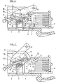
- La figure 1 de ce dessin représente, en élévation schématique, les éléments essentiels de ce mode de réalisation, en position de travail.
- La figure 2 représente les mêmes éléments que la figure 1, en position de repos.
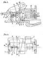
- La figure 3 représente les mêmes éléments que la figure 1, en position momentanée de nettoyage de contacts.
- La figure 4 représente une vue de bout du porte-contact avec coupes partielles passant par l'axe du porte-contact et par son point de réaction.
- L'interrupteur représenté aux figures 1 et 2 comprend un boîtier isolant dont on n'a représenté qu'un élément de paroi 1. A l'intérieur de ce boîtier, un contact mobile 2, en forme de lame, est monté sur un porte-contact 3, en matière isolante, susceptible de basculer, autour d'un axe X, entre une position de travail (figure 1) et une position de repos (figure 2). Dans la position de travail (figure 1), le porte-contact 3 met une zone active 4 du contact mobile 2 en contact avec une zone active 5 d'un contact fixe 6, sous une pression déterminée par l'action d'un ressort de compression hélicoidal 7. Dans la position de repos (figure 2), le porte-contact 3 maintient les deux zones actives 4, 5 écartées l'une de l'autre. Selon le mode de réalisation représenté, les zones actives, 4 et 5 sont constituées par des surfaces appartenant respectivement à un rivet 8, rapporté sur le contact mobile 2, et à un rivet 9, rapporté sur le contact fixe 6.
- Le contact fixe 6 est assujetti au boîtier par des moyens non représentés. Le porte-contact 3 est monté sur le boîtier, par exemple à l'aide de tourillons 10 engagés dans des trous correspondants du boîtier, de façon à pouvoir osciller autour de l'axe X.
- Conformément à l'invention, le ressort de compression 7 agit sur le contact mobile 2 en un point P de celui-ci qui est situé sur la même face 11 que la zone active 4 de ce contact mobile 2 de façon à pousser ce dernier contre le porte-contact 3 en deux points Q et R qui sont écartés l'un de l'autre et situés sur l'autre face 12 du contact mobile 2. On désigne par "point d'action" le point P et par "points de réaction" les points Q et R. Le point de réaction Q est plus éloigné de la zone active 4 et le point de réaction R moins éloigné de cette zone active 4 que le point d'action P. En d'autres termes, si l'on néglige l'épaisseur du contact mobile 2, on peut dire que le point d'action est situé entre les points Q et R.
- De préférence, le point P est constitué par une déformation du contact mobile 2 en forme de rouleau ou saillie -hémicylindrique 15 tandis que les points de réaction Q et R sont matérialisés respectivement par des saillies hémicylindriques 13 et 14 venues de moulage avec le porte-contact 3. Comme montré sur les figures, le point d'action P est situé à peu près à mi-distance des points Q et R, si l'on néglige l'épaisseur du contact mobile 2.
- Le ressort de compression 7 prend appui, par une extrémité, sur l'élément de paroi 1 et agit par son autre extrémité sur le rouleau 15. A cet effet, cette autre extrémité peut être constituée par une spire 16 plus ou moins fermée sur elle-même en anneau.
- Le porte-contact 3 est actionné par des moyens (non montrés) qui l'attaquent par un trou 17 ménagé à l'une de ses extrémités, l'ensemble étant tel que le porte-contact 3 soit toujours arrêté alternativement aux deux positions de fin de course représentées. Dans la position de fin de course représentée à la figure 1 (position de travail), où les deux zones actives 4 et 5 sont au contact l'une de l'autre et où le contact mobile 2 touche le porte-contact 3 au point de réaction R le moins éloigné de sa zone active 4, l'ensemble est tel qu'il existe (tout au moins en l'absence d'usure notable des rivets 8 et 9) une course d'usure a entre la face 12 du contact mobile 2 et le porte-contact 3 au niveau de l'autre point de réaction P, c'est-à-dire au niveau de la saillie 13.
- De préférence, la lame constituant le contact mobile 2 est contre-coudée, comme représenté sur les figures, entre deux parties rectilignes à peu près parallèles entre elles, à savoir une première partie où sont situés les points d'action P et de réaction Q, R et une deuxième partie où est située la zone active 4, grâce à la présence d'une partie intermédiaire inclinée 18, de façon à accroître l'espace disponible pour le logement du ressort 7.
- Enfin, la distance b entre le point de réaction R le moins éloigné de la zone active 4 du contact mobile 2 et le point P est de préférence de l'ordre de la moitié de la distance c entre ce même point de réaction R et la susdite zone active 4, ces distances étant mesurées selon la direction longitudinale du contact mobile 2.
- Par ailleurs, le porte-contact 3 présente, de part et d'autre des extrémités latérales du bossage formant la zone de réaction R, deux petits bossages 19 orientés vers le bas et pénétrant à assez faible jeu dans deux encoches latérales 20 pratiquées dans la première partie rectiligne du contact 2, à faible distance de la partie inclinée 18. On assure de la sorte une liaison solidarisant sensiblement le porte-contact 3 et le contact 2 dans la direction longitudinale du contact mobile 2.
- On obtient ainsi un interrupteur dont le fonctionnement est le suivant. Dans la position de travail représentée à la figure 1, le ressort 7, en agissant au point d'action P, tend à faire tourner le contact mobile 2 autour du point de réaction R dans le sens des aiguilles d'une montre, c'est-à-dire à appliquer la zone active 4 du contact mobile 2 contre la zone active 5 du contact fixe 6 avec une force qui, en raison du rapport existant entre les distances b et c, est de l'ordre de la moitié de la force exercée par le ressort 7 sur le contact mobile 2 au point d'action P. Au niveau du point de réaction Q, il existe la course d'usure a.
- Lorsque, partant de la position de travail de la figure 1, on fait basculer le porte-contact 3 dans le sens inverse des aiguilles d'une montre autour de l'axe X, ceci fait se soulever la saillie 14 jusqu'à ce que, sous l'action du ressort 7, le contact mobile 2 vienne toucher le porte-contact 3 non seulement au point de réaction R, mais également au point de réaction Q, les zones actives 4 et 5 étant restées jusqu'ici appuyées l'une sur l'autre par le ressort 7. A partir de cette position intermédiaire où le contact mobile 2 est venu toucher le point de réaction Q, le ressort 7 cesse d'exercer sur le contact mobile 2 un couple tendant à le faire basculer autour du- point de réaction R, dans le sens des aiguilles d'une montre. En effet, en exerçant sa poussée entre les points de réaction .Q et R sur le contact mobile 2, il solidarise celui-ci avec le porte-contact 3 qui entraîne donc le contact mobile 2 jusqu'à la position de repos représentée à la figure 2.
- Lorsque, partant de la position de repos représentée à la figure 2, on fait basculer le porte-contact 3 dans le sens des aiguilles d'une montre, le porte-contact 3 entraîne avec lui le contact mobile 2 jusqu'à la position intermédiaire susvisée où sa zone active 4 vient toucher la zone active 5 du contact fixe 6. On se trouve alors dans la position de la figure 3, sur laquelle on voit que la partie active 4 du contact mobile 2 vient toucher la zone active 5 du contact fixe 6 dans une position légèrement inclinée et décalée vers la gauche, comme on le voit sur cette figure. Puis, lors de la poursuite du mouvement du porte-contact 3, le contact mobile 2, s'écarte du porte-contact 3 au niveau du point de réaction Q et le ressort 7 exerce sur le contact mobile 2 un couple croissant qui tend à le faire tourner dans le sens des aiguilles d'une montre autour du point de réaction R. On se retrouve enfin dans la situation décrite en référence à la figure 1.
- On note que pendant cette partie finale du basculement, le point de réaction R continue de descendre, ce qui oblige le contact 2 à se rapprocher de l'horizontale, ce qui force la partie active 4 du contact mobile 2 à riper sur la zone active 5 du contact fixe jusqu'à la position finale de la figure 1, provoquant ainsi chaque fois un auto-nettoyage des zones de contact.
- L'usure des rivets 8 et 9 se traduit simplement par une diminution de la course d'usure initiale a, sans perturber le fonctionnement del'interrupteur.
- Comme on le voit, les rivets de contacts 8, 9 sont situés à l'intérieur d'une chambre de coupure 21 refermée de tous côtés à l'exception d'une ouverture 22 nécessaire pour le débattement de l'extrémité du contact mobile 2 qui porte le rivet 8. Cette chambre 21 contient des armatures 23 capables de créer un champ magnétique de désionisation lors de la séparation des rivets de contact 8, 9.
- Conformément à une invention de préférence associée à la combinaison des porte-contact 3, contact mobile 2 et ressort 7, le porte-contact présente, au niveau de l'ouverture 22, une lèvre 24 dont la surface extérieure orientée vers la chambre 21 est cylindrique circulaire centrée sur l'axe de pivotement X. Cette lèvre 24 détermine avec l'extrémité 25 de la paroi de la chambre 21 un passage très étroit 26 présent quelle que soit la position du porte-contact 3, ce qui accroît notablement l'isolation électrique de la chambre 21 et de son contenu par rapport au reste (non vu) de l'interrupteur.
- Il est à noter, qu'outre l'isolation accrue, l'ensemble, agencé conformément à l'invention, du porte-contact 3, du contact mobile 2 et du ressort 7, apporte un accroissement important de la rapidité d'ouverture des contacts.
Claims (9)
Priority Applications (1)
| Application Number | Priority Date | Filing Date | Title |
|---|---|---|---|
| AT84401956T ATE44191T1 (de) | 1983-10-04 | 1984-10-01 | Schalter mit schwenkbarem kontakttraeger. |
Applications Claiming Priority (2)
| Application Number | Priority Date | Filing Date | Title |
|---|---|---|---|
| FR8315783 | 1983-10-04 | ||
| FR8315783A FR2552926B1 (fr) | 1983-10-04 | 1983-10-04 | Perfectionnements apportes aux interrupteurs a porte-contact basculant |
Publications (2)
| Publication Number | Publication Date |
|---|---|
| EP0142404A1 true EP0142404A1 (fr) | 1985-05-22 |
| EP0142404B1 EP0142404B1 (fr) | 1989-06-21 |
Family
ID=9292795
Family Applications (1)
| Application Number | Title | Priority Date | Filing Date |
|---|---|---|---|
| EP84401956A Expired EP0142404B1 (fr) | 1983-10-04 | 1984-10-01 | Perfectionnements apportés aux interrupteurs à porte-contact basculant |
Country Status (4)
| Country | Link |
|---|---|
| EP (1) | EP0142404B1 (fr) |
| AT (1) | ATE44191T1 (fr) |
| DE (1) | DE3478774D1 (fr) |
| FR (1) | FR2552926B1 (fr) |
Cited By (2)
| Publication number | Priority date | Publication date | Assignee | Title |
|---|---|---|---|---|
| FR2583571A1 (fr) * | 1985-06-12 | 1986-12-19 | Merlin Gerin | Disjoncteur basse tension a coupure amelioree. |
| WO2005031775A1 (fr) * | 2003-09-25 | 2005-04-07 | Siemens Aktiengesellschaft | Disjoncteur de puissance basse tension a mouvement de contact radial par integration des supports de contact dans l'arbre de commande |
Families Citing this family (5)
| Publication number | Priority date | Publication date | Assignee | Title |
|---|---|---|---|---|
| FR2709205B1 (fr) * | 1993-08-17 | 1995-10-20 | Merlin Gerin | Interrupteur différentiel tétrapolaire. |
| DE19948695B4 (de) * | 1999-09-30 | 2009-02-05 | Siemens Ag | Niederspannungs-Leistungsschalter mit einem bewegbaren Kontaktträger mit Endlagen-Haltefeder |
| WO2001024207A1 (fr) * | 1999-09-30 | 2001-04-05 | Siemens Aktiengesellschaft | Disjoncteur basse tension a chambre de commutation et porte-contact mobile |
| FR2999793A1 (fr) * | 2012-12-14 | 2014-06-20 | Schneider Electric Ind Sas | Arbre de support des contacts mobiles dans un appareil de coupure du courant electrique, et appareil de coupure de courant le comportant, en particulier un disjoncteur de branchement. |
| DE102015110644A1 (de) | 2015-07-02 | 2017-01-05 | Phoenix Contact Gmbh & Co. Kg | Vorrichtung zur trennbaren elektrischen Verbindung |
Citations (3)
| Publication number | Priority date | Publication date | Assignee | Title |
|---|---|---|---|---|
| DE643986C (de) * | 1935-03-13 | 1937-04-22 | Oerlikon Maschf | Elektrischer Schalter |
| US3286067A (en) * | 1963-06-06 | 1966-11-15 | Ite Circuit Breaker Ltd | Contact pressure arrangement for circuit breaker mechanism |
| EP0081805A2 (fr) * | 1981-12-12 | 1983-06-22 | Licentia Patent-Verwaltungs-GmbH | Agencement de contact pour un interrupteur automatique |
-
1983
- 1983-10-04 FR FR8315783A patent/FR2552926B1/fr not_active Expired
-
1984
- 1984-10-01 EP EP84401956A patent/EP0142404B1/fr not_active Expired
- 1984-10-01 AT AT84401956T patent/ATE44191T1/de not_active IP Right Cessation
- 1984-10-01 DE DE8484401956T patent/DE3478774D1/de not_active Expired
Patent Citations (3)
| Publication number | Priority date | Publication date | Assignee | Title |
|---|---|---|---|---|
| DE643986C (de) * | 1935-03-13 | 1937-04-22 | Oerlikon Maschf | Elektrischer Schalter |
| US3286067A (en) * | 1963-06-06 | 1966-11-15 | Ite Circuit Breaker Ltd | Contact pressure arrangement for circuit breaker mechanism |
| EP0081805A2 (fr) * | 1981-12-12 | 1983-06-22 | Licentia Patent-Verwaltungs-GmbH | Agencement de contact pour un interrupteur automatique |
Cited By (4)
| Publication number | Priority date | Publication date | Assignee | Title |
|---|---|---|---|---|
| FR2583571A1 (fr) * | 1985-06-12 | 1986-12-19 | Merlin Gerin | Disjoncteur basse tension a coupure amelioree. |
| EP0206882A1 (fr) * | 1985-06-12 | 1986-12-30 | Merlin Gerin | Disjoncteur basse tension à coupure améliorée |
| US4672157A (en) * | 1985-06-12 | 1987-06-09 | Merlin Gerin | Low voltage circuit breaker with improved breaking |
| WO2005031775A1 (fr) * | 2003-09-25 | 2005-04-07 | Siemens Aktiengesellschaft | Disjoncteur de puissance basse tension a mouvement de contact radial par integration des supports de contact dans l'arbre de commande |
Also Published As
| Publication number | Publication date |
|---|---|
| DE3478774D1 (en) | 1989-07-27 |
| FR2552926A1 (fr) | 1985-04-05 |
| FR2552926B1 (fr) | 1985-12-27 |
| EP0142404B1 (fr) | 1989-06-21 |
| ATE44191T1 (de) | 1989-07-15 |
Similar Documents
| Publication | Publication Date | Title |
|---|---|---|
| EP0142404B1 (fr) | Perfectionnements apportés aux interrupteurs à porte-contact basculant | |
| FR2575707A1 (fr) | Dispositif de detection de changement de vitesse pour la commande d'un embrayage associe a une boite de vitesses | |
| EP0871185B1 (fr) | Bouton-poussoir à effet sonore et tactile | |
| EP2398029B1 (fr) | Interrupteur à commande monostable et à contact bistable | |
| FR2482364A1 (fr) | Interrupteur de detection de position d'enclenchement d'une boite de vitesses | |
| EP2564408B1 (fr) | Dispositif d'arret d'urgence | |
| EP0248716A1 (fr) | Commutateur pour vehicules automobiles | |
| EP0028561B1 (fr) | Touche de commande à rappel magnétique | |
| EP0100245B1 (fr) | Commutateur électrique miniature | |
| FR2480994A1 (fr) | Interrupteur perfectionne du type a bouton poussoir | |
| EP1595271B1 (fr) | Bouton-poussoir rupteur conjoncteur | |
| EP0403329A1 (fr) | Perfectionnements aux interrupteurs à coupure automatique, notamment aux disjoncteurs et disjoncteurs différentiels | |
| CH648953A5 (fr) | Interrupteur electrique a ressort de contact prearme. | |
| FR2763663A3 (fr) | Dispositif d'actionnement a double autorisation, en particulier pour taille-haies et outils analogues | |
| BE1005375A0 (fr) | Dispositif d'enclenchement brusque d'un levier de contact monte de facon mobile, en particulier pour un commutateur de protection contre des courants de defaut. | |
| EP1162521A1 (fr) | Dispositif de commande à déclic et montre munie d'un tel dispositif | |
| EP0406097B1 (fr) | Interrupteur, notamment pour vehicules automobiles | |
| EP0216645B1 (fr) | Dispositif anti-inversion du mouvement relatif de deux organes respectivement mâle et femelle, dont l'un est actionné manuellement | |
| FR2646008A1 (fr) | Potentiometre rotatif | |
| FR2652444A1 (fr) | Interrupteur electrique a rappel magnetique. | |
| FR2481911A1 (fr) | Presse-agrumes manuel a mouvement rotatoire alternatif | |
| FR2525385A1 (fr) | Commutateur destine notamment a etre installe sur des plaques de montage | |
| FR2641408A1 (fr) | Interrupteur electrique rotatif notamment a commande manuelle | |
| CH695076A5 (fr) | Interrupteur de type push-push. | |
| EP1052664A1 (fr) | Dispositif étanche de détection de position à ouverture brusque |
Legal Events
| Date | Code | Title | Description |
|---|---|---|---|
| PUAI | Public reference made under article 153(3) epc to a published international application that has entered the european phase |
Free format text: ORIGINAL CODE: 0009012 |
|
| AK | Designated contracting states |
Designated state(s): AT BE CH DE GB IT LI NL SE |
|
| 17P | Request for examination filed |
Effective date: 19851112 |
|
| 17Q | First examination report despatched |
Effective date: 19870522 |
|
| GRAA | (expected) grant |
Free format text: ORIGINAL CODE: 0009210 |
|
| AK | Designated contracting states |
Kind code of ref document: B1 Designated state(s): AT BE CH DE GB IT LI NL SE |
|
| PG25 | Lapsed in a contracting state [announced via postgrant information from national office to epo] |
Ref country code: SE Effective date: 19890621 Ref country code: NL Effective date: 19890621 Ref country code: AT Effective date: 19890621 |
|
| REF | Corresponds to: |
Ref document number: 44191 Country of ref document: AT Date of ref document: 19890715 Kind code of ref document: T |
|
| REF | Corresponds to: |
Ref document number: 3478774 Country of ref document: DE Date of ref document: 19890727 |
|
| ITF | It: translation for a ep patent filed | ||
| GBT | Gb: translation of ep patent filed (gb section 77(6)(a)/1977) | ||
| NLV1 | Nl: lapsed or annulled due to failure to fulfill the requirements of art. 29p and 29m of the patents act | ||
| PLBE | No opposition filed within time limit |
Free format text: ORIGINAL CODE: 0009261 |
|
| STAA | Information on the status of an ep patent application or granted ep patent |
Free format text: STATUS: NO OPPOSITION FILED WITHIN TIME LIMIT |
|
| 26N | No opposition filed | ||
| ITTA | It: last paid annual fee | ||
| PGFP | Annual fee paid to national office [announced via postgrant information from national office to epo] |
Ref country code: BE Payment date: 19940929 Year of fee payment: 11 |
|
| PGFP | Annual fee paid to national office [announced via postgrant information from national office to epo] |
Ref country code: DE Payment date: 19940930 Year of fee payment: 11 |
|
| PGFP | Annual fee paid to national office [announced via postgrant information from national office to epo] |
Ref country code: GB Payment date: 19941003 Year of fee payment: 11 |
|
| PGFP | Annual fee paid to national office [announced via postgrant information from national office to epo] |
Ref country code: CH Payment date: 19941017 Year of fee payment: 11 |
|
| PG25 | Lapsed in a contracting state [announced via postgrant information from national office to epo] |
Ref country code: GB Effective date: 19951001 |
|
| PG25 | Lapsed in a contracting state [announced via postgrant information from national office to epo] |
Ref country code: LI Effective date: 19951031 Ref country code: CH Effective date: 19951031 Ref country code: BE Effective date: 19951031 |
|
| BERE | Be: lapsed |
Owner name: S.A. HAGER ELECTRO Effective date: 19951031 |
|
| GBPC | Gb: european patent ceased through non-payment of renewal fee |
Effective date: 19951001 |
|
| REG | Reference to a national code |
Ref country code: CH Ref legal event code: PL |
|
| PG25 | Lapsed in a contracting state [announced via postgrant information from national office to epo] |
Ref country code: DE Effective date: 19960702 |