EP0142409A1 - Roboterhand und Verfahren zum Handhaben von Leiterplatten - Google Patents
Roboterhand und Verfahren zum Handhaben von Leiterplatten Download PDFInfo
- Publication number
- EP0142409A1 EP0142409A1 EP84402030A EP84402030A EP0142409A1 EP 0142409 A1 EP0142409 A1 EP 0142409A1 EP 84402030 A EP84402030 A EP 84402030A EP 84402030 A EP84402030 A EP 84402030A EP 0142409 A1 EP0142409 A1 EP 0142409A1
- Authority
- EP
- European Patent Office
- Prior art keywords
- pincer
- board
- units
- pinching
- unit
- Prior art date
- Legal status (The legal status is an assumption and is not a legal conclusion. Google has not performed a legal analysis and makes no representation as to the accuracy of the status listed.)
- Granted
Links
Images


Classifications
-
- B—PERFORMING OPERATIONS; TRANSPORTING
- B25—HAND TOOLS; PORTABLE POWER-DRIVEN TOOLS; MANIPULATORS
- B25J—MANIPULATORS; CHAMBERS PROVIDED WITH MANIPULATION DEVICES
- B25J15/00—Gripping heads and other end effectors
- B25J15/08—Gripping heads and other end effectors having finger members
- B25J15/10—Gripping heads and other end effectors having finger members with three or more finger members
-
- B—PERFORMING OPERATIONS; TRANSPORTING
- B25—HAND TOOLS; PORTABLE POWER-DRIVEN TOOLS; MANIPULATORS
- B25J—MANIPULATORS; CHAMBERS PROVIDED WITH MANIPULATION DEVICES
- B25J15/00—Gripping heads and other end effectors
- B25J15/02—Gripping heads and other end effectors servo-actuated
-
- H—ELECTRICITY
- H05—ELECTRIC TECHNIQUES NOT OTHERWISE PROVIDED FOR
- H05K—PRINTED CIRCUITS; CASINGS OR CONSTRUCTIONAL DETAILS OF ELECTRIC APPARATUS; MANUFACTURE OF ASSEMBLAGES OF ELECTRICAL COMPONENTS
- H05K13/00—Apparatus or processes specially adapted for manufacturing or adjusting assemblages of electric components
- H05K13/0061—Tools for holding the circuit boards during processing; handling transport of printed circuit boards
-
- Y—GENERAL TAGGING OF NEW TECHNOLOGICAL DEVELOPMENTS; GENERAL TAGGING OF CROSS-SECTIONAL TECHNOLOGIES SPANNING OVER SEVERAL SECTIONS OF THE IPC; TECHNICAL SUBJECTS COVERED BY FORMER USPC CROSS-REFERENCE ART COLLECTIONS [XRACs] AND DIGESTS
- Y10—TECHNICAL SUBJECTS COVERED BY FORMER USPC
- Y10T—TECHNICAL SUBJECTS COVERED BY FORMER US CLASSIFICATION
- Y10T29/00—Metal working
- Y10T29/49—Method of mechanical manufacture
- Y10T29/49002—Electrical device making
- Y10T29/49117—Conductor or circuit manufacturing
- Y10T29/49124—On flat or curved insulated base, e.g., printed circuit, etc.
- Y10T29/4913—Assembling to base an electrical component, e.g., capacitor, etc.
Definitions
- This invention relates to hand type grippers used with robots in automated systems. More specifically, this invention is a gripper for holding and transporting loaded circuit boards.
- Printed circuit boards are tested prior to distribution in order to determine whether they have any electrical defects. This is generally accomplished by connecting a circuit board to be tested to a test system by means of a test fixture having a plurality of probes for contacting certain points on the back of the board.
- the circuit boards are generally delivered to a test area in a container which is commonly referred to as a "tote box."
- the tote box has a series of slots, each of which contains one circuit board.
- the dimensions of each slot are sufficiently large to accommodate a variety of board sizes and to facilitate loading of the tote box.
- the space between each slot is sufficient to accommodate the components which extend above the surface of the board.
- the circuit boards are relatively loosely fitted within the tote box
- a test station is usually operated by a person standing within reach of the tote box and the test fixture of a test system. The operator repetitively reaches into the tote box for a circuit board to be tested, places it on the test fixture and waits for the test to be completed. Upon completion of the test, the board is removed from the test fixture and placed with known good boards or routed to a repair area.
- One device utilizes a large number of vacuum cups which grasp and hold the loaded circuit boards by means of suction.
- the vacuum cups are arranged on the hand so as to correspond with components having a flat surface in order to obtain a secure grip on the board. Due to the lack of large flat surface areas on most printed circuit boards, and also due to the movement of the robot itself, which tends to dislodge the boards, a large number of vacuum cups are generally required. Also, since the vacuum cups must be in a pattern corresponding to that of the components having flat surfaces, a different hand member has to be used for each different type of circuit board to be tested.
- Another approach which has been used for transporting loaded circuit boards utilizes a pair of grooved parallel bars.
- the circuit board is positioned between the bars after which the bars are moved together, thereby wedging the circuit board between the bars and within the grooves.
- One drawback of this approach is that the circuit board must have two parallel edges and the edges must be free from components so as not to be damaged when the bars grasp the board.
- Other difficulties are encountered when the circuit boards being tested are flexible and cannot be secured simply by wedging them between the bars or when the circuit boards, which can vary in thickness by about 30 mils, are of a thickness that does not correspond to the groove in the bars.
- this approach tends to damage the test fixture gasket or loosen the connection between the gasket and the test fixture.
- the robotic hand of this invention is capable of reaching into the relatively narrow confines of a tote box slot and gripping a loaded circuit board previously placed therein with a degree of accuracy typical of current practice. Also, the robotic hand of this invention can grip a circuit board by its edges without causinq any damage to the board or any of the components found thereon. The resulting grip is firm enough and secure enough to withstand the inertial forces encountered in a high speed robotic system. Finally, the device to be described herein is suitable for picking up a circuit board from a recessed position within a test fixture gasket without damaging the gasket in any way or . loosening its connection with the test fixture.
- a hand member having at least two opposing pincer units.
- Each pincer unit has a thumb and finger set operated between a pinching state where the gap between them is relatively closed and a releasing state wherein the gap is relatively opened.
- the circuit board can be held in a spaced-apart relationship with respect to the palm which allows room for the various circuit board components.
- the opposing pincers are also mounted so as to allow the distances between the pincers to be varied. This permits the pincers to squeeze the circuit board between themselves while pinching its edges. This dual securing aspect of the invention allows for a sufficiently firm grip of the circuit board without damaging any of the components.
- the fingers extend outwardly from the hand, they can be used to depress the gaskets surrounding the circuit board and can then be extended beneath the circuit board for removing it from the test fixture without damaging the gasket.
- the method of this invention involves the steps of bracketing a-pair of opposing edges of a circuit board with pincer units having variable pinching gaps, squeezing the board between the pincer units by moving the pincer units toward one another and finally, pinching the edges of the circuit board.
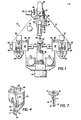
- Figs. 1, 2 and 3 show the general organization of the robot hand of this invention.
- hand 10 is provided with one front pincer unit 18 distal from and generally on the axis of a wrist connector 14 and two rear pincer units 16 on either side of wrist connector 14 mounted in an opposed relationship with front pincer unit 18.
- a palm plate 12 serves as a base upon which the pincer units are mounted.
- a pincer unit may be considered for the purpose of this description as including a thumb and finger set in which the thumb is slideably mounted on the finger so as to define a variable pinching gap.
- a circuit board 32 may be held by its opposing edges between the pinching gaps of front pincer unit 18 and rear pincer units 16.
- Opposing edges for the purpose of this description is intended to refer to edges of a circuit board which are generally on opposite sides thereof.
- the various cylinders to be referred to in this description are all pneumatic air cylinders, but the pneumatic lines and fittings have been omitted for the sake of simplicity.
- the operation of the cylinders is controlled through solenoids 70, 72 and 74 which are conveniently mounted on palm 12.
- the pneumatic lines running between these solenoids and the cylinders as well as the electrical connections between the solenoids and the robot control circuits are shown schematically in Fig. 9 to be described below.
- each rear pincer unit 16 has an associated pinching cylinder 20 and a squeeze cylinder 24. These structures are mounted on a sliding block 52 which, in turn, is slideably mounted on a track 54. Track 54 is rigidly mounted on palm 12. Sliding block 52 and track 54 comprise a slide assembly 50 which may be of any conventional type. The purpose of this slide assembly arrangement is to permit the two rear pincer units to be moved toward and away from one another so that the pincer units may be strategically placed for engagement with a clear portion of the edge of a circuit board 12.
- the positions of sliding blocks 52 are controlled by adjusting screws 67. Once the blocks have been moved to desired positions, they may be fixed there by means of adjustment brackets 66 and hold down bolts 65.
- each rear pincer unit 16 is capable of two types of movement, a lateral movement transverse to the axis of wrist connector 14 for selection of a clear spot on the circuit board to be picked up and a prehensiling movement for use in actually picking up or releasing a circuit board.
- Front pincer unit 18 is mounted on front pinching cylinder 22 which, in turn, is mounted on a driving bracket 58 as shown in Figs. 1, 2 and 3.
- a squeeze cylinder 26 is connected to driving bracket 58 by means of piston rod 44.
- a limit bar 45 is mounted transversely to piston rod 44 at its connection with driving bracket 58. All of these structures are mounted on a sliding block 60 by means of front mounting bracket 62, all as more clearly shown in Fig. 6. Still referring to Fig. 1, it will be seen that sliding block 60 is mounted on a track 57 which is rigidly mounted on palm 12 on the axis of wrist connector 14. Track 57 and mounting block 60 comprise a slide assembly 56 similar to rear slide assemblies 50.
- front sliding block 60 may be adjusted by operation of the adjusting screw 59 and anchored in a selected position by means of front adjustment bracket 68 and hold down bolt 69.
- front pincer unit 18 is driven by cylinder 26 in prehensiling movements toward and away from the rear pincer units 16 within a limited range of movement for a given position of sliding block 60.
- the range of the prehensiling movement of front pincer unit 18 can thus be translated toward and away from wrist connector 14 by repositioning sliding block 60. This permits hand 10 to accommodate circuit boards of various sizes.
- Fig. 4 together with Figs. 5(a), 5(b) and 5(c), show rear pincer units 16 and their associated structures in greater detail.
- Each pincer unit 16 includes a finger 39 and an L-shaped thumb 38.
- Finger 39 is rigidly connected to a bracket 34 and thumb 38 is slideably mounted on finger 39.
- the distal end of finger 39 is provided with a flange 41.
- the space between flange 41 and the distal end of thumb 38 forms a pinching gap 43 into which the edge of a circuit board may be inserted.
- Thumb 38 is connected to pinch cylinder 20 by means of a piston rod 36.
- thumb 38 is resiliently driven so as to slide along finger 39. In this manner, the size of pinching gap 43 is controlled. It may be noted that flange 41 and the distal end of thumb 38 are beveled so as to draw the pincer unit 16 toward a board being pinched between them.
- mounting bracket 34 is connected to sliding block 52 by means of hinge 30.
- Squeeze cylinder 24 is operatively connected to bracket 34 by means of linkage 42 and piston rod 43.
- bracket 34 and rear pincer unit 16 is tilted with respect to palm 12 in prehensiling movements in which pincer unit 16 is resiliently driven toward or away from front pincer unit 18.
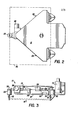
- FIGs.6 and 7 show front pincer unit 18 and its associated structures in greater detail.
- Front pincer unit 18 has a finger 19 rigidly mounted on a circular plate 13.
- Circular plate 13 is, in turn, rigidly mounted on air cylinder 22.
- a thumb 17 is slideably mounted on finger 19 and it has a circular connector 15 at its proximal end for connection with the piston rod of air cylinder 22.
- Finger 19 is provided with a flange 21.
- flange 21 and the distal end of thumb 17 are preferably beveled for promoting a secure pinching grip on the edge of a circuit board.
- front squeeze cylinder 26 drives limit bar 45 and driving bracket 58 by means of its piston rod 44.
- This imparts a prehensiling movement to front pincer unit 18 along the direction of the wrist axis of the hand so that front pincer unit 18 may be moved toward or away from rear pincer units 16.
- Limit bar 45 protrudes transversely on either side of driving bracket 58.
- a rear limit adjustment bolt 46 and a forward limit adjustment bolt 48 are mounted so as to interfere with the movement of limit bar 45, thereby limiting the prehensiling movement of front pincer unit 18 accordingly.
- a structure is also provided to impose a short forward movement limit on limit bar 45 and thus, front pincer unit 18.
- short limit cylinder 28 is mounted by means of a bracket 29 on the side of sliding block 60.
- An adjustment bolt 49 is mounted transversely on the piston rod 51 (see Fig. 1) of short limit cylinder 28. By operation of the piston within cylinder 28, short limit adjustment bolt 49 may be positioned either to block the forward movement of limit bar 45 or not.
- driving bracket 58 and limit bar 45 are slideably mounted with respect to mounting bracket 62.
- Driving bracket 58 is supported by a spacer block 64 which slides along bracket 62, as shown in Figs. 6 and 8(a), (b) and (c).
- the range of prehensiling movements of front pincer unit 18, as limited by bolts 46 and 48, can be translated by the repositioning of sliding block 60 on track 57 shown in Figs. 1 and 6.
- Fig. 9 shows the manner in which the air cylinders described above are related to and controlled by the robot control circuits 76.
- Pinch solenoid 70 controls the operation of front pinch cylinder 22 and rear pinch cylinders 20 through pneumatic lines 71 and 73.
- Pinch solenoid 70 has two modes of operation, one in which air pressure from a compressed air source (not shown) is admitted to line 71 only and one in which air pressure is admitted to line 73 only.
- solenoid 70 activates lines 71, the pistons in cylinders 20 and 22 are driven in one direction so as to resiliently urge their associated thumbs toward their corresponding flanges, thereby closing the pinching gaps.
- solenoid 70 activates pneumatic line 73
- the pistons within cylinders 20 and 22 operate to retract the thumbs connected to them.
- solenoid 72 controls the operation of squeeze cylinders 24 and 26 through pneumatic lines 75 and 77.
- solenoid 72 activates line 75, front squeeze cylinder 26 and rear squeeze cylinders 24 operate in one direction to resiliently drive their associated pincer units in prehensiling movements away from one another.
- the movement of front pincer unit 18 will either be limited to its short forward limit or its long forward limit depending upon the condition of solenoid 74 and air cylinder 28.
- pneumatic line 77 When pneumatic line 77 is activated, cylinders 26 and 24 will serve to resiliently drive their associated pincer units toward one another, thereby squeezing a circuit board located between them. Again, while hand 10 is holding a circuit board, a suitable amount of air pressure may be maintained in line 77 in order to provide a continuous squeezing action against the edges of the board.
- the solenoids 70, 72 and 74 are controlled by robot control circuits 76 through electrical lines 84, 86 and 88.
- Figs. 5(a), 5(b) and 5(c) showing the movements of the rear pincer units and in Figs. 8(a), 8(b) and 8(c), showing the movements of the front pincer unit 18.
- the pincer units are shown picking up a circuit board 33 resting on a gasket 35. The movements shown are controlled by the robot control circuits.
- the pincer units have been spread apart by the operation of their associated squeeze cylinders as described above. It will be understood, however, that short limit air cylinder 28 will have been operated to impose the short forward limit on the travel of the front pincer unit 18 since this is necessary to avoid damaging gasket 35 as explained earlier.
- the pincer units would be spread so far apart that upon driving them together, they might entrap a portion of the gasket between themselves and the board.
- the opposing edges of circuit board 33 may be bracketed between the front and rear pincer units, as illustrated in Figs. 5(a) and 8(a).
- the hand 10 and, thus, fingers 39 and 19 will be driven slightly against the gasket 35 thereby depressing it and moving the pinching gaps to positions where they are opposite and facing their associated edge of circuit board 33.
- squeeze cylinders24 and 26 are operated to resiliently drive the front and rear pincer units toward one another thereby squeezing circuit board 33 between them. This position is illustrated in Figs.
- pinching cylinders 20 and 22 are operated to drive their thumbs toward the flanges of their associated fingers, thus pinching the edges of the circuit board.
- the robot may then be operated to pick up and transport the board to a desired station.
- the short limit air cylinder 28 will have been operated to impose the short forward limit on the travel of the front pincer unit 18. This is to prevent the pincer units from being spread apart so far upon releasing a board as to cause undue outward pressure on it. Such undue pressure could cause the gasket to tear or to become dislodged from its fixturing system.
- the operation of the robot hand of this invention is similar when it is used to pick up a circuit board from a tote box.
- One important difference is that the short forward limit on the travel of front pincer unit 18 is not imposed. That is because the location of a circuit board within a tote box is generally not as precise as it is on a test fixture. Accordingly, the front and rear pincer units must be more spread apart from one another for bracketing the circuit board to be picked up.
- the robotic hand of this invention offers a number of significant advantages.
- the use of relatively narrow fingers, coupled with the limitations on their prehensiling movements, enable the hand to depress a test fixture gasket and remove a circuit board therefrom without damaging the gasket.
- the hand is able to pick up a board less accurately placed within a tote box.
- the rear pincer units form a lateral reference line when they are driven to their squeezing positions. In those positions, the rear pincer units are substantially perpendicular to the palm 12 and the resulting reference line between them is useful in programming the movements of the robot system.
- This arrangement also permits the front pincer unit 18 to adopt various positions along the wrist axis in order to accommodate variations in the widths of circuit boards.
- Another advantage of the invention described above concerns its continuous application of pinching and squeezing forces on the circuit board.
- the pneumatics employed permit the continuous application of these forces so that the grip of the hand can adapt itself to flexure of a board as it is being transported.
Landscapes
- Engineering & Computer Science (AREA)
- Robotics (AREA)
- Mechanical Engineering (AREA)
- Manufacturing & Machinery (AREA)
- Microelectronics & Electronic Packaging (AREA)
- Manipulator (AREA)
- Supply And Installment Of Electrical Components (AREA)
Applications Claiming Priority (2)
| Application Number | Priority Date | Filing Date | Title |
|---|---|---|---|
| US06/540,415 US4616971A (en) | 1983-10-11 | 1983-10-11 | Robotic hand and method for manipulating printed circuit boards |
| US540415 | 1983-10-11 |
Publications (2)
| Publication Number | Publication Date |
|---|---|
| EP0142409A1 true EP0142409A1 (de) | 1985-05-22 |
| EP0142409B1 EP0142409B1 (de) | 1989-01-11 |
Family
ID=24155359
Family Applications (1)
| Application Number | Title | Priority Date | Filing Date |
|---|---|---|---|
| EP84402030A Expired EP0142409B1 (de) | 1983-10-11 | 1984-10-10 | Roboterhand und Verfahren zum Handhaben von Leiterplatten |
Country Status (5)
| Country | Link |
|---|---|
| US (1) | US4616971A (de) |
| EP (1) | EP0142409B1 (de) |
| JP (1) | JPS60143700A (de) |
| CA (1) | CA1264173A (de) |
| DE (1) | DE3476037D1 (de) |
Cited By (3)
| Publication number | Priority date | Publication date | Assignee | Title |
|---|---|---|---|---|
| AT388528B (de) * | 1987-03-25 | 1989-07-25 | Oesterr Forsch Seibersdorf | Greifer |
| US8515557B2 (en) | 2007-11-19 | 2013-08-20 | Cochlear Limited | Electrode array for a cochlear implant |
| CN107225068A (zh) * | 2017-08-08 | 2017-10-03 | 合肥杰代机电科技有限公司 | 一种汽车零部件的自动涂油装置 |
Families Citing this family (19)
| Publication number | Priority date | Publication date | Assignee | Title |
|---|---|---|---|---|
| US4735452A (en) * | 1986-12-19 | 1988-04-05 | Texas Instruments Incorporated | Article gripper assembly |
| US5132914A (en) * | 1988-04-01 | 1992-07-21 | Restaurant Technology, Inc. | Food preparation system and method |
| US4922435A (en) * | 1988-04-01 | 1990-05-01 | Restaurant Technology, Inc. | Food preparation robot |
| US5172328A (en) * | 1988-04-01 | 1992-12-15 | Restaurant Technology, Inc. | Food preparation system and method |
| US5080415A (en) * | 1988-04-22 | 1992-01-14 | Beckman Instruments, Inc. | Robot gripper having auxiliary degree of freedom |
| US4900214A (en) * | 1988-05-25 | 1990-02-13 | American Telephone And Telegraph Company | Method and apparatus for transporting semiconductor wafers |
| DE3823621A1 (de) * | 1988-07-12 | 1990-01-18 | Fraunhofer Ges Forschung | Greifer zum greifen und handhaben von werkstuecken |
| US5222310A (en) * | 1990-05-18 | 1993-06-29 | Semitool, Inc. | Single wafer processor with a frame |
| US5228553A (en) * | 1992-02-24 | 1993-07-20 | Circuit Chemistry Equipment, Inc. | Drive mechanism for a conveyor of a printer circuit board processor |
| US6273483B1 (en) * | 1996-03-28 | 2001-08-14 | Mcmaster University | Three orthogonal directions movable fingers for holding and/or manipulating a three-dimensional object |
| US5971456A (en) * | 1996-04-01 | 1999-10-26 | Conway Exploitatie En Beheer, B.V. | Bakery system with gripper assemblies |
| KR100257625B1 (ko) * | 1997-01-27 | 2000-06-01 | 강정근 | Pcb 검사장치 |
| JP2002122630A (ja) * | 2000-10-17 | 2002-04-26 | Ando Electric Co Ltd | Icテスタ調整装置 |
| DE102004020590A1 (de) * | 2004-04-27 | 2005-11-17 | Carl Zeiss Jena Gmbh | Greifvorrichtung |
| DE102006060240A1 (de) * | 2006-12-20 | 2008-06-26 | Schmidt & Heinzmann Gmbh & Co. Kg | Vorrichtung mit einer Hebevorrichtung |
| WO2008091706A1 (en) * | 2007-01-25 | 2008-07-31 | Radio Robots Llc | Remotely controlled system and method for the preparation of a user-defined food product or beverage |
| US20090297323A1 (en) * | 2008-05-30 | 2009-12-03 | Genesis Worldwide Ii, Inc. | Method and apparatus for stacking sheet materials |
| US8172292B1 (en) * | 2009-11-04 | 2012-05-08 | SACMI USA, Ltd. | Arm tool for packing trays in boxes |
| CN110315563B (zh) * | 2019-06-24 | 2024-08-27 | 格力电器(郑州)有限公司 | 一种上下料夹具、夹具组件及机器人 |
Citations (2)
| Publication number | Priority date | Publication date | Assignee | Title |
|---|---|---|---|---|
| US3968885A (en) * | 1973-06-29 | 1976-07-13 | International Business Machines Corporation | Method and apparatus for handling workpieces |
| EP0060896A1 (de) * | 1980-09-30 | 1982-09-29 | Fanuc Ltd. | Hand für industrielle roboter |
Family Cites Families (10)
| Publication number | Priority date | Publication date | Assignee | Title |
|---|---|---|---|---|
| US2925300A (en) * | 1956-07-09 | 1960-02-16 | Ralph R Kelley | Material handling device |
| DE1114713B (de) * | 1957-12-03 | 1961-10-05 | Yale & Towne Mfg Co | Transportfahrzeug mit Anhaengerkupplung |
| US3640519A (en) * | 1969-08-13 | 1972-02-08 | William M Halstead | Handling and heat-dissipating device for electrical components |
| US3901547A (en) * | 1973-05-14 | 1975-08-26 | Ii Frank R Skinner | Multiple prehension mechanism |
| US3866966A (en) * | 1973-05-14 | 1975-02-18 | Ii Frank R Skinner | Multiple prehension manipulator |
| US3884363A (en) * | 1973-09-13 | 1975-05-20 | Bendix Corp | Programmable universal transfer device |
| EP0001686B1 (de) * | 1977-10-20 | 1981-11-04 | Imperial Chemical Industries Plc | Industrieller Manipulator zum dicht gegeneinander Stapeln von Gegenständen und Stapelnverfahren unter Verwendung des Manipulators |
| US4252360A (en) * | 1979-06-12 | 1981-02-24 | Gallaher Jr John K | Mechanical handling apparatus |
| US4375936A (en) * | 1980-08-18 | 1983-03-08 | Harnischfeger Corporation | Stacker crane for movement of coils |
| AT373512B (de) * | 1982-05-19 | 1984-01-25 | Voest Alpine Ag | Vorrichtung zum zufuehren plattenfoermiger werkstuecke zu einer werkzeugmaschine |
-
1983
- 1983-10-11 US US06/540,415 patent/US4616971A/en not_active Expired - Fee Related
-
1984
- 1984-10-10 DE DE8484402030T patent/DE3476037D1/de not_active Expired
- 1984-10-10 CA CA000465001A patent/CA1264173A/en not_active Expired
- 1984-10-10 EP EP84402030A patent/EP0142409B1/de not_active Expired
- 1984-10-11 JP JP59211543A patent/JPS60143700A/ja active Pending
Patent Citations (2)
| Publication number | Priority date | Publication date | Assignee | Title |
|---|---|---|---|---|
| US3968885A (en) * | 1973-06-29 | 1976-07-13 | International Business Machines Corporation | Method and apparatus for handling workpieces |
| EP0060896A1 (de) * | 1980-09-30 | 1982-09-29 | Fanuc Ltd. | Hand für industrielle roboter |
Non-Patent Citations (3)
| Title |
|---|
| IBM TECHNICAL DISCLOSURE BULLETIN, vol. 19, no. 3, August 1976, pages 949-950, New York, US; R.S. MYERS: "Detachable handle grip" * |
| IBM TECHNICAL DISCLOSURE BULLETIN, vol. 19, no. 8, January 1977, page 2941, New York, US; R.F. BOUDAH et al.: "Substrate gripper" * |
| IBM TECHNICAL DISCLOSURE BULLETIN, vol. 25, no. 5, October 1982, pages 2334-2335, New York, US; G. DELANNOY: "Holder device for handling semiconductor wafers" * |
Cited By (3)
| Publication number | Priority date | Publication date | Assignee | Title |
|---|---|---|---|---|
| AT388528B (de) * | 1987-03-25 | 1989-07-25 | Oesterr Forsch Seibersdorf | Greifer |
| US8515557B2 (en) | 2007-11-19 | 2013-08-20 | Cochlear Limited | Electrode array for a cochlear implant |
| CN107225068A (zh) * | 2017-08-08 | 2017-10-03 | 合肥杰代机电科技有限公司 | 一种汽车零部件的自动涂油装置 |
Also Published As
| Publication number | Publication date |
|---|---|
| DE3476037D1 (en) | 1989-02-16 |
| EP0142409B1 (de) | 1989-01-11 |
| CA1264173A (en) | 1990-01-02 |
| US4616971A (en) | 1986-10-14 |
| JPS60143700A (ja) | 1985-07-29 |
Similar Documents
| Publication | Publication Date | Title |
|---|---|---|
| EP0142409B1 (de) | Roboterhand und Verfahren zum Handhaben von Leiterplatten | |
| US4611846A (en) | Gripper head | |
| US4593820A (en) | Robotic, in-transit, device tester/sorter | |
| JP4026773B2 (ja) | 食材の把持移動方法及び装置 | |
| US6218852B1 (en) | Automated circuit board testing apparatus | |
| CN209684804U (zh) | 一种用于货物装载的机械抓手 | |
| US7134833B2 (en) | Servo adjustable gripper device | |
| US6502881B2 (en) | Gripper for picking apparatus of a module IC handler | |
| EP0286178B1 (de) | Greifvorrichtung | |
| CN108177849B (zh) | 运输电连接器用的托盘 | |
| WO2022194701A1 (en) | A gripper device configured to be attached to a robotic device and to pick up a food product from a pick up area and to release it from a releasing location to a receiving location | |
| GB2415944A (en) | Apparatus fro moving products using camera and flat gripper | |
| US5468111A (en) | Disc loading and unloading assembly | |
| JPS6216818A (ja) | 折りたたみ作業における金属板自動操作方法および装置 | |
| US5056844A (en) | Multiple jaw centering head structure for surface mounted component placement machines | |
| EP1327913A3 (de) | Verfahren und Vorrichtung zur Übertragung und Ladung einer Maske mittels eines robotischen Endeffektors | |
| JP3049981B2 (ja) | チップ部品の電極形成システム | |
| US6192655B1 (en) | Hosiery manipulation device and method | |
| CN115091493A (zh) | 机械手、机器人、自动化生产线及家用电器的安装方法 | |
| US4671722A (en) | Automatic positioning of electronic components on a walking beam | |
| EP0525364A1 (de) | Vorrichtung zum Speichern und Transportieren von oberflächenempfindlichen Leiterplatten | |
| US6260261B1 (en) | Straddle-mount assembly tool and method | |
| CN217256286U (zh) | 一种机械设计制造用机械手 | |
| JPH1191951A (ja) | Icチューブマガジン切り出し機構 | |
| CN223983879U (zh) | 手套翻面机构 |
Legal Events
| Date | Code | Title | Description |
|---|---|---|---|
| PUAI | Public reference made under article 153(3) epc to a published international application that has entered the european phase |
Free format text: ORIGINAL CODE: 0009012 |
|
| AK | Designated contracting states |
Designated state(s): DE FR GB NL SE |
|
| 17P | Request for examination filed |
Effective date: 19851108 |
|
| 17Q | First examination report despatched |
Effective date: 19860926 |
|
| RAP1 | Party data changed (applicant data changed or rights of an application transferred) |
Owner name: CIMM, INC. |
|
| GRAA | (expected) grant |
Free format text: ORIGINAL CODE: 0009210 |
|
| AK | Designated contracting states |
Kind code of ref document: B1 Designated state(s): DE FR GB NL SE |
|
| PG25 | Lapsed in a contracting state [announced via postgrant information from national office to epo] |
Ref country code: SE Effective date: 19890111 Ref country code: NL Effective date: 19890111 Ref country code: FR Free format text: THE PATENT HAS BEEN ANNULLED BY A DECISION OF A NATIONAL AUTHORITY Effective date: 19890111 |
|
| REF | Corresponds to: |
Ref document number: 3476037 Country of ref document: DE Date of ref document: 19890216 |
|
| EN | Fr: translation not filed | ||
| NLV1 | Nl: lapsed or annulled due to failure to fulfill the requirements of art. 29p and 29m of the patents act | ||
| PGFP | Annual fee paid to national office [announced via postgrant information from national office to epo] |
Ref country code: GB Payment date: 19891031 Year of fee payment: 6 |
|
| PLBE | No opposition filed within time limit |
Free format text: ORIGINAL CODE: 0009261 |
|
| STAA | Information on the status of an ep patent application or granted ep patent |
Free format text: STATUS: NO OPPOSITION FILED WITHIN TIME LIMIT |
|
| PGFP | Annual fee paid to national office [announced via postgrant information from national office to epo] |
Ref country code: DE Payment date: 19891116 Year of fee payment: 6 |
|
| 26N | No opposition filed | ||
| PG25 | Lapsed in a contracting state [announced via postgrant information from national office to epo] |
Ref country code: GB Effective date: 19901010 |
|
| GBPC | Gb: european patent ceased through non-payment of renewal fee | ||
| PG25 | Lapsed in a contracting state [announced via postgrant information from national office to epo] |
Ref country code: DE Effective date: 19910702 |