EP0142424A2 - Mischstrahlpumpe mit veränderlichem Durchschnitt - Google Patents
Mischstrahlpumpe mit veränderlichem Durchschnitt Download PDFInfo
- Publication number
- EP0142424A2 EP0142424A2 EP84402165A EP84402165A EP0142424A2 EP 0142424 A2 EP0142424 A2 EP 0142424A2 EP 84402165 A EP84402165 A EP 84402165A EP 84402165 A EP84402165 A EP 84402165A EP 0142424 A2 EP0142424 A2 EP 0142424A2
- Authority
- EP
- European Patent Office
- Prior art keywords
- sleeve
- profile
- enclosure
- convergent
- elastic
- Prior art date
- Legal status (The legal status is an assumption and is not a legal conclusion. Google has not performed a legal analysis and makes no representation as to the accuracy of the status listed.)
- Granted
Links
- 239000000463 material Substances 0.000 claims abstract description 6
- 238000007789 sealing Methods 0.000 claims abstract description 3
- 230000036316 preload Effects 0.000 claims description 3
- 238000000034 method Methods 0.000 claims 4
- 238000001514 detection method Methods 0.000 claims 1
- 239000012530 fluid Substances 0.000 abstract description 10
- 239000007864 aqueous solution Substances 0.000 abstract description 2
- 239000007900 aqueous suspension Substances 0.000 abstract description 2
- 230000008020 evaporation Effects 0.000 abstract 1
- 238000001704 evaporation Methods 0.000 abstract 1
- 238000011144 upstream manufacturing Methods 0.000 description 5
- 238000004519 manufacturing process Methods 0.000 description 3
- 230000035939 shock Effects 0.000 description 3
- 230000006978 adaptation Effects 0.000 description 2
- 230000000694 effects Effects 0.000 description 2
- 230000001939 inductive effect Effects 0.000 description 2
- 239000000203 mixture Substances 0.000 description 2
- 230000003068 static effect Effects 0.000 description 2
- 241001474791 Proboscis Species 0.000 description 1
- 230000015572 biosynthetic process Effects 0.000 description 1
- 230000015556 catabolic process Effects 0.000 description 1
- 239000012141 concentrate Substances 0.000 description 1
- 235000013365 dairy product Nutrition 0.000 description 1
- 238000006731 degradation reaction Methods 0.000 description 1
- 238000010612 desalination reaction Methods 0.000 description 1
- 239000012895 dilution Substances 0.000 description 1
- 238000010790 dilution Methods 0.000 description 1
- 229920001971 elastomer Polymers 0.000 description 1
- 239000000806 elastomer Substances 0.000 description 1
- 235000013305 food Nutrition 0.000 description 1
- 230000000977 initiatory effect Effects 0.000 description 1
- 239000007788 liquid Substances 0.000 description 1
- 229920003052 natural elastomer Polymers 0.000 description 1
- 229920001194 natural rubber Polymers 0.000 description 1
- 230000037452 priming Effects 0.000 description 1
- 239000013535 sea water Substances 0.000 description 1
- 238000004513 sizing Methods 0.000 description 1
- 229920003051 synthetic elastomer Polymers 0.000 description 1
- 239000005061 synthetic rubber Substances 0.000 description 1
Images

Classifications
-
- F—MECHANICAL ENGINEERING; LIGHTING; HEATING; WEAPONS; BLASTING
- F04—POSITIVE - DISPLACEMENT MACHINES FOR LIQUIDS; PUMPS FOR LIQUIDS OR ELASTIC FLUIDS
- F04F—PUMPING OF FLUID BY DIRECT CONTACT OF ANOTHER FLUID OR BY USING INERTIA OF FLUID TO BE PUMPED; SIPHONS
- F04F5/00—Jet pumps, i.e. devices in which flow is induced by pressure drop caused by velocity of another fluid flow
- F04F5/44—Component parts, details, or accessories not provided for in, or of interest apart from, groups F04F5/02 - F04F5/42
- F04F5/48—Control
Definitions
- the present invention relates to an ejector-mixer with a proboscis effect and is particularly applicable to energy transformers intended for the recompression of gas or soft vapor.
- thermocompressors are dilution devices in which an energy exchange is carried out between a motor gas (or vapor) and an aspirated gas (or vapor).
- Thermocompressors being static devices, are very simple and reliable. They are used in particular on evaporators in the food industry to concentrate an aqueous solution and / or suspension (sugar refinery, dairy, distillery, seawater desalination plant, etc.)
- an ejector comprises a driving nozzle which opens, delivering a flow rate Q I of vapor or gas at a total pressure P 'and a total temperature T', in a steam or gas suction pipe (induced flow Q ", total pressure P" at total temperature T ").
- This pipe is extended by a mixer where energy is exchanged between the two flows then by a diffuser which transforms the kinetic energy resulting from the flow mixture Q, into a static pressure P at the total temperature T.
- An improvement of the ejectors has been to replace the single inductor by a plurality of nozzles which thanks to the division of the engine jet improves the quality of the mixture and allows for a given recompression rate to increase the entrainment rate.
- variable geometry is produced, integrating all or part of the converging, the neck at the outlet of this converging and at least part of the diverging.
- the initial priming is carried out at a neck dimension greater than or equal to the critical dimension, the neck is then closed until the desired pressure level is obtained allowing passage of the supersonic flow (in the convergent) to subsonic flow (in the divergent) without shock wave formation and with minimization of losses.
- the part with variable profile advantageously consists of a sleeve or tube of elastic deformable material on which a pressurized fluid is acted controlled by the upstream pressure, the suction pressure or the downstream pressure of the ejector.
- the deformation of the elastic wall adapts the neck to the conditions of use.
- the elastic sleeve is subjected to a tension preload by stretching its body, before application of the deformation pressure. It can then be seen that the sleeve, no longer working in buckling as before but in extension, determines a deformation with a harmonious profile recalling the nozzle profile commonly used in aerodynamics (see Figures 3 and 4).
- the ejector-mixer shown in FIG. 5 comprises a driving nozzle 1 made up of a plurality of inductor nozzles 2 (in this case seven) opening into a duct with a convervent-divergent profile 3 disposed along the axis A-A.
- This duct 3 comprises upstream a suction sleeve 4 with a highly convergent profile enveloping the nozzle driving 1.
- the upstream end of this sleeve is in contact with a hollow body 5, which can be connected at 6 to a pipe conveying the induced flow: soft steam for example.
- the nozzles 2 are fixed to a duct 7 through which they are supplied with inducing fluid, said duct being for this purpose connected, possibly by a strainer 8, to a pipe for supplying the inducing fluid: live steam for example.
- the diffuser Downstream of the conduit 3, the diffuser consists of a divergent 11 which can be connected to the user member.
- connection wall between the suction sleeve 4 and the diffuser 11, comprises a substantially cylindrical part 12 followed by a part with low converging taper 13 and finally by a part with variable profile 14.
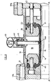
- This profile 14 consists (FIG. 6) of a sleeve 15 of elastic deformable material (natural or synthetic rubber, elastomer), housed in a cylindrical casing 16 inserted, with sealing, between adjacent flanges 17 A and 17 B.
- the enclosure 18 thus formed is supplied with pressurized fluid by means 19 (pipe).
- the sleeve 15 is extended on either side by two annular flanges 21 and 22 forming an integral part of the sleeve.
- the supply of fluid under pressure to the enclosure 18 is ensured by a pressure regulator 35 connected to a source of fluid pressure (preferably liquid) by the pipe 36 on the one hand and to the means 19 on the other hand.
- This regulator 35 is controlled by the upstream driving pressure, the suction pressure or the downstream pressure discharged from the ejector through the conduit 37 connected to a pressure tap disposed in the suction sleeve 4, the mixer or diffuser 11.
- a change in the upstream, aspirated or downstream reference pressure causes an action on the regulator 35 which acts on the sending of the fluid into the enclosure 18, which has the effect of modifying the internal profile of the sleeve 15, which passes through example of the position shown in full lines in Figure 6 to the position shown in broken lines.
- one of the end flanges - for example the left flange designated by 21 - is firmly locked in a fixed jaw 40 integral with the casing 16
- the opposite end flange 22 is firmly gripped in a movable jaw 41 sliding axially in the casing 16 under the action of a jack (not shown) whose rod is seen at 42 and which may be a screw jack.
- the latter is stretched by moving the movable jaw 41 to the right of the drawing using the jack 42, thereby printing on the sleeve 15 tension preload.
- the chamber 18 is put back in overpressure to obtain the required converging-diverging sonic neck profile.
- FIG. 6 shows in 43 such a detector which is seen at 44 a radial feeler finger urged by a spring 45 so that its free end 44 A is in permanent contact with the external surface of the elastic sleeve 15 around its mid-length.
Landscapes
- Engineering & Computer Science (AREA)
- Physics & Mathematics (AREA)
- Fluid Mechanics (AREA)
- Mechanical Engineering (AREA)
- General Engineering & Computer Science (AREA)
- Jet Pumps And Other Pumps (AREA)
- Percussion Or Vibration Massage (AREA)
- Gas Burners (AREA)
- Preparation Of Clay, And Manufacture Of Mixtures Containing Clay Or Cement (AREA)
- Disintegrating Or Milling (AREA)
Priority Applications (1)
| Application Number | Priority Date | Filing Date | Title |
|---|---|---|---|
| AT84402165T ATE28350T1 (de) | 1983-11-10 | 1984-10-29 | Mischstrahlpumpe mit veraenderlichem durchschnitt. |
Applications Claiming Priority (2)
| Application Number | Priority Date | Filing Date | Title |
|---|---|---|---|
| FR8317869 | 1983-11-10 | ||
| FR8317869A FR2554874B1 (fr) | 1983-11-10 | 1983-11-10 | Ejecteur-melangeur a effet de trompe a section variable et application |
Publications (3)
| Publication Number | Publication Date |
|---|---|
| EP0142424A2 true EP0142424A2 (de) | 1985-05-22 |
| EP0142424A3 EP0142424A3 (de) | 1985-06-19 |
| EP0142424B1 EP0142424B1 (de) | 1987-07-15 |
Family
ID=9293972
Family Applications (1)
| Application Number | Title | Priority Date | Filing Date |
|---|---|---|---|
| EP84402165A Expired EP0142424B1 (de) | 1983-11-10 | 1984-10-29 | Mischstrahlpumpe mit veränderlichem Durchschnitt |
Country Status (5)
| Country | Link |
|---|---|
| US (1) | US4586873A (de) |
| EP (1) | EP0142424B1 (de) |
| AT (1) | ATE28350T1 (de) |
| DE (1) | DE3464787D1 (de) |
| FR (1) | FR2554874B1 (de) |
Cited By (3)
| Publication number | Priority date | Publication date | Assignee | Title |
|---|---|---|---|---|
| FR2632688A1 (fr) * | 1988-06-10 | 1989-12-15 | Entrepose Montalev | Ejecteur |
| CN102072209A (zh) * | 2009-11-24 | 2011-05-25 | J.施迈茨有限公司 | 压缩空气驱动的负压发生器 |
| EP3517856A1 (de) * | 2017-12-20 | 2019-07-31 | Lennox Industries Inc. | Verfahren und vorrichtung zur bestätigung der kalibrierung eines kältemitteldetektors |
Families Citing this family (20)
| Publication number | Priority date | Publication date | Assignee | Title |
|---|---|---|---|---|
| DK158109C (da) * | 1988-02-04 | 1990-08-20 | Dems Eng | Omstillelig ejektor |
| US4800920A (en) * | 1988-04-05 | 1989-01-31 | Whitey Co. | Pinch valve |
| US4877053A (en) * | 1988-04-05 | 1989-10-31 | Whitey Co. | Pinch valve |
| US4899783A (en) * | 1988-09-30 | 1990-02-13 | Whitey Co. | Pinch valve |
| US4938245A (en) * | 1989-09-25 | 1990-07-03 | Fluidmaster, Inc. | Low noise toilet tank valve |
| AU7239491A (en) * | 1990-01-17 | 1991-08-05 | Helios Research Corp. | Silencer system for hydrokinetic amplifier |
| US5326468A (en) * | 1992-03-02 | 1994-07-05 | Cox Dale W | Water remediation and purification method and apparatus |
| US6079628A (en) * | 1994-04-06 | 2000-06-27 | Kenny; Thomas M. | Self-contained temperature and pressure operated pinch valve |
| IL122396A0 (en) * | 1997-12-02 | 1998-06-15 | Pekerman Oleg | Method of heating and/or homogenizing of liquid products in a steam-liquid injector |
| FR2788109B1 (fr) * | 1998-12-30 | 2001-06-08 | Total Raffinage Distribution | Dispositif pour ameliorer le brulage des combustibles gazeux |
| US6877960B1 (en) * | 2002-06-05 | 2005-04-12 | Flodesign, Inc. | Lobed convergent/divergent supersonic nozzle ejector system |
| US8505310B2 (en) * | 2008-10-22 | 2013-08-13 | General Electric Company | Gas turbine ejector and method of operation |
| US8794902B1 (en) | 2010-01-26 | 2014-08-05 | II Daniel K. Van Ness | System and method to improve the exhaust pressure across a RAM air turbine through secondary flow mixing |
| US8480361B1 (en) * | 2010-01-26 | 2013-07-09 | Mainstream Engineering Corporation | Enhanced system and method to increase the total-to-static pressure ratio across a RAM air turbine using surface contoured flow agitators |
| CN102865258B (zh) * | 2012-10-17 | 2015-10-07 | 南通赛孚机械设备有限公司 | 一种低能耗蒸汽喷射真空泵 |
| WO2017169219A1 (ja) * | 2016-04-01 | 2017-10-05 | 株式会社テイエルブイ | エゼクタ、エゼクタの製造方法及びディフューザの出口流路の設定方法 |
| WO2017169218A1 (ja) * | 2016-04-01 | 2017-10-05 | 株式会社テイエルブイ | エゼクタ、エゼクタの製造方法及びディフューザの出口流路の設定方法 |
| DE102017124699A1 (de) * | 2017-10-23 | 2019-04-25 | Avl Emission Test Systems Gmbh | Abgasprobenentnahmesystem |
| CN108672123B (zh) * | 2018-07-06 | 2021-01-19 | 西安交通大学 | 一种混合腔喉部面积可调节的喷射器 |
| CN109738032B (zh) * | 2019-03-14 | 2024-08-23 | 湖南大麓科技有限公司 | 一种管道流量测定装置和方法 |
Family Cites Families (12)
| Publication number | Priority date | Publication date | Assignee | Title |
|---|---|---|---|---|
| US1457799A (en) * | 1920-12-31 | 1923-06-05 | Westinghouse Electric & Mfg Co | Fluid-translating device |
| DE415379C (de) * | 1924-05-24 | 1925-06-20 | Werft Akt Ges Fa Deutsche | Dampfstrahl-Mischvorrichtung mit Verdichtungsduese zur Erzeugung von Mischdampf aus hoch- und niedriggespanntem Dampf |
| US2142520A (en) * | 1935-08-15 | 1939-01-03 | Ingersoll Rand Co | Thermocompressor |
| US2074480A (en) * | 1936-03-18 | 1937-03-23 | Ingersoll Rand Co | Thermocompressor |
| DE1054798B (de) * | 1958-02-05 | 1959-04-09 | Bopp & Reuther Gmbh | Druckmittelbetaetigtes Schlauchventil |
| US3276480A (en) * | 1965-07-01 | 1966-10-04 | Barber Colman Co | Regulator for constant volume of gas flow |
| US3448691A (en) * | 1967-07-03 | 1969-06-10 | David M Frazier | Energy controller |
| SU390304A1 (ru) * | 1971-08-23 | 1973-07-11 | Струйный насос | |
| US3791764A (en) * | 1972-03-01 | 1974-02-12 | Garrett Corp | Variable area ratio jet pump |
| GB1420215A (en) * | 1972-03-09 | 1976-01-07 | British Gas Corp | Jet boosters |
| US3942724A (en) * | 1974-08-01 | 1976-03-09 | S.R.C. Laboratories, Inc. | Variable throat nozzle |
| FR2534983A1 (fr) * | 1982-10-20 | 1984-04-27 | Chacoux Claude | Compresseur supersonique a jet |
-
1983
- 1983-11-10 FR FR8317869A patent/FR2554874B1/fr not_active Expired
-
1984
- 1984-10-29 DE DE8484402165T patent/DE3464787D1/de not_active Expired
- 1984-10-29 EP EP84402165A patent/EP0142424B1/de not_active Expired
- 1984-10-29 AT AT84402165T patent/ATE28350T1/de not_active IP Right Cessation
- 1984-11-09 US US06/669,861 patent/US4586873A/en not_active Expired - Fee Related
Cited By (7)
| Publication number | Priority date | Publication date | Assignee | Title |
|---|---|---|---|---|
| FR2632688A1 (fr) * | 1988-06-10 | 1989-12-15 | Entrepose Montalev | Ejecteur |
| CN102072209A (zh) * | 2009-11-24 | 2011-05-25 | J.施迈茨有限公司 | 压缩空气驱动的负压发生器 |
| EP2333350A1 (de) * | 2009-11-24 | 2011-06-15 | J. Schmalz GmbH | Druckluftbetriebener Unterdruckerzeuger |
| US8596990B2 (en) | 2009-11-24 | 2013-12-03 | J. Schmalz Gmbh | Pneumatic vacuum generator |
| EP3517856A1 (de) * | 2017-12-20 | 2019-07-31 | Lennox Industries Inc. | Verfahren und vorrichtung zur bestätigung der kalibrierung eines kältemitteldetektors |
| US10760838B2 (en) | 2017-12-20 | 2020-09-01 | Lennox Industries Inc. | Method and apparatus for refrigerant detector calibration confirmation |
| US11378313B2 (en) | 2017-12-20 | 2022-07-05 | Lennox Industries Inc. | Method and apparatus for refrigerant detector calibration confirmation |
Also Published As
| Publication number | Publication date |
|---|---|
| FR2554874A1 (fr) | 1985-05-17 |
| FR2554874B1 (fr) | 1988-04-15 |
| EP0142424B1 (de) | 1987-07-15 |
| ATE28350T1 (de) | 1987-08-15 |
| DE3464787D1 (en) | 1987-08-20 |
| EP0142424A3 (de) | 1985-06-19 |
| US4586873A (en) | 1986-05-06 |
Similar Documents
| Publication | Publication Date | Title |
|---|---|---|
| EP0142424B1 (de) | Mischstrahlpumpe mit veränderlichem Durchschnitt | |
| EP0417009B1 (de) | Vorrichtung und Anlage zur Reinigung von Abzugskanälen, insbesondere bei Erdölbohrlöchern | |
| EP1947385B1 (de) | Vorrichtung zur Kraftstoffeinspritzung in eine Strömungsmaschine | |
| FR2928567A1 (fr) | Buse de pulverisation de liquide et pulverisateur de liquide comprenant une telle buse | |
| EP0069637A2 (de) | Verfahren und Vorrichtung zum Pulverisieren eines festen Brennstoffes | |
| FR2601665A1 (fr) | Dispositif de remplissage a retour d'air separe | |
| FR2652610A1 (fr) | Procede de pompage de melange liquide gaz dans un puits d'extraction petrolier et dispositif de mise en óoeuvre du procede. | |
| FR2482478A1 (fr) | Dispositif de douche pour applications sanitaires | |
| EP0253706B1 (de) | Ventil zum Ablassen der Flüssigkeitsphase eines Zweiphasenfluidums | |
| EP0049190A1 (de) | Vorrichtung zur Luftfilmkühlung für das Flammrohr eines Gasturbinentriebwerks | |
| EP0216674A1 (de) | Spritzgerät zum Spritzen eines pulverförmigen Stoffes | |
| EP0170566B1 (de) | Verfahren zur Heizung des Heisswindes eines Hochofens mit Hilfe eines Plasmabrenners | |
| FR2588779A1 (fr) | Separateur a vortex pour liquide heterogene a debit variable | |
| FR2541390A1 (fr) | Ejecteur-melangeur a effet de trompe, utilise notamment comme thermocompresseur | |
| EP0177423B1 (de) | Innenmischende Schneidbrennerdüse | |
| FR2607728A1 (fr) | Dispositif pour le balayage directionnel d'une surface par jets de fluide | |
| BE850012A (fr) | Perfectionnements aux dispositifs a jet | |
| FR2565322A1 (fr) | Dispositif d'injection d'un liquide dans un tube et generateur de vapeur comportant ce dispositif | |
| CA1094810A (fr) | Dispositif de dispersion pour gaz de rejet avec une pluralite d'ajutages d'injection | |
| EP0051021A2 (de) | Verfahren zum Feindispergieren eines Fluids in einem Fluidstrom höherer Dichte, insbesondere eines Gases in einer Flüssigkeit, sowie eine Vorrichtung zu seiner Durchführung | |
| FR2759121A1 (fr) | Dipositif d'aspiration d'un fluide a l'interieur d'une conduite de circulation d'un deuxieme fluide | |
| BE876956A (fr) | Dispositif de soufflage a niveau de bruit bas | |
| CH468597A (fr) | Installation de mise en émulsion d'hydrocarbures liquides et d'eau, destinée à l'alimentation d'un brûleur | |
| EP1122115B1 (de) | Vorrichtung zum Betanken eines Kraftstoffbehälters insbesondere für ein Kraftfahrzeug | |
| BE537785A (de) |
Legal Events
| Date | Code | Title | Description |
|---|---|---|---|
| PUAI | Public reference made under article 153(3) epc to a published international application that has entered the european phase |
Free format text: ORIGINAL CODE: 0009012 |
|
| PUAL | Search report despatched |
Free format text: ORIGINAL CODE: 0009013 |
|
| AK | Designated contracting states |
Designated state(s): AT BE CH DE FR GB IT LI LU NL SE |
|
| AK | Designated contracting states |
Designated state(s): AT BE CH DE FR GB IT LI LU NL SE |
|
| RTI1 | Title (correction) | ||
| 17P | Request for examination filed |
Effective date: 19850924 |
|
| 17Q | First examination report despatched |
Effective date: 19860708 |
|
| GRAA | (expected) grant |
Free format text: ORIGINAL CODE: 0009210 |
|
| AK | Designated contracting states |
Kind code of ref document: B1 Designated state(s): AT BE CH DE FR GB IT LI LU NL SE |
|
| REF | Corresponds to: |
Ref document number: 28350 Country of ref document: AT Date of ref document: 19870815 Kind code of ref document: T |
|
| ITF | It: translation for a ep patent filed | ||
| REF | Corresponds to: |
Ref document number: 3464787 Country of ref document: DE Date of ref document: 19870820 |
|
| PLBE | No opposition filed within time limit |
Free format text: ORIGINAL CODE: 0009261 |
|
| STAA | Information on the status of an ep patent application or granted ep patent |
Free format text: STATUS: NO OPPOSITION FILED WITHIN TIME LIMIT |
|
| 26N | No opposition filed | ||
| ITTA | It: last paid annual fee | ||
| EPTA | Lu: last paid annual fee | ||
| EAL | Se: european patent in force in sweden |
Ref document number: 84402165.9 |
|
| PGFP | Annual fee paid to national office [announced via postgrant information from national office to epo] |
Ref country code: AT Payment date: 19950922 Year of fee payment: 12 |
|
| PGFP | Annual fee paid to national office [announced via postgrant information from national office to epo] |
Ref country code: FR Payment date: 19950925 Year of fee payment: 12 |
|
| PGFP | Annual fee paid to national office [announced via postgrant information from national office to epo] |
Ref country code: LU Payment date: 19951001 Year of fee payment: 12 |
|
| PGFP | Annual fee paid to national office [announced via postgrant information from national office to epo] |
Ref country code: SE Payment date: 19951017 Year of fee payment: 12 |
|
| PGFP | Annual fee paid to national office [announced via postgrant information from national office to epo] |
Ref country code: GB Payment date: 19951024 Year of fee payment: 12 |
|
| PGFP | Annual fee paid to national office [announced via postgrant information from national office to epo] |
Ref country code: DE Payment date: 19951027 Year of fee payment: 12 |
|
| PGFP | Annual fee paid to national office [announced via postgrant information from national office to epo] |
Ref country code: NL Payment date: 19951031 Year of fee payment: 12 |
|
| PGFP | Annual fee paid to national office [announced via postgrant information from national office to epo] |
Ref country code: CH Payment date: 19951102 Year of fee payment: 12 |
|
| PGFP | Annual fee paid to national office [announced via postgrant information from national office to epo] |
Ref country code: BE Payment date: 19951116 Year of fee payment: 12 |
|
| PG25 | Lapsed in a contracting state [announced via postgrant information from national office to epo] |
Ref country code: LU Free format text: LAPSE BECAUSE OF NON-PAYMENT OF DUE FEES Effective date: 19961029 Ref country code: GB Effective date: 19961029 Ref country code: AT Effective date: 19961029 |
|
| PG25 | Lapsed in a contracting state [announced via postgrant information from national office to epo] |
Ref country code: SE Effective date: 19961030 |
|
| PG25 | Lapsed in a contracting state [announced via postgrant information from national office to epo] |
Ref country code: LI Effective date: 19961031 Ref country code: CH Effective date: 19961031 Ref country code: BE Effective date: 19961031 |
|
| BERE | Be: lapsed |
Owner name: BERTIN & CIE Effective date: 19961031 |
|
| PG25 | Lapsed in a contracting state [announced via postgrant information from national office to epo] |
Ref country code: NL Effective date: 19970501 |
|
| REG | Reference to a national code |
Ref country code: CH Ref legal event code: PL |
|
| GBPC | Gb: european patent ceased through non-payment of renewal fee |
Effective date: 19961029 |
|
| PG25 | Lapsed in a contracting state [announced via postgrant information from national office to epo] |
Ref country code: FR Effective date: 19970630 |
|
| NLV4 | Nl: lapsed or anulled due to non-payment of the annual fee |
Effective date: 19970501 |
|
| PG25 | Lapsed in a contracting state [announced via postgrant information from national office to epo] |
Ref country code: DE Effective date: 19970701 |
|
| EUG | Se: european patent has lapsed |
Ref document number: 84402165.9 |
|
| REG | Reference to a national code |
Ref country code: FR Ref legal event code: ST |