EP0142428A1 - Neigungsvorrichtung für Sitze, insbesondere für Kraftwagensitze - Google Patents
Neigungsvorrichtung für Sitze, insbesondere für Kraftwagensitze Download PDFInfo
- Publication number
- EP0142428A1 EP0142428A1 EP84402229A EP84402229A EP0142428A1 EP 0142428 A1 EP0142428 A1 EP 0142428A1 EP 84402229 A EP84402229 A EP 84402229A EP 84402229 A EP84402229 A EP 84402229A EP 0142428 A1 EP0142428 A1 EP 0142428A1
- Authority
- EP
- European Patent Office
- Prior art keywords
- flange
- mechanism according
- pawl
- spring
- housing
- Prior art date
- Legal status (The legal status is an assumption and is not a legal conclusion. Google has not performed a legal analysis and makes no representation as to the accuracy of the status listed.)
- Granted
Links
- 230000007246 mechanism Effects 0.000 title claims abstract description 30
- 238000006073 displacement reaction Methods 0.000 claims description 2
- 230000001681 protective effect Effects 0.000 claims description 2
- 230000000717 retained effect Effects 0.000 claims description 2
- 238000004519 manufacturing process Methods 0.000 description 4
- 238000002788 crimping Methods 0.000 description 1
- 230000000881 depressing effect Effects 0.000 description 1
- 230000035939 shock Effects 0.000 description 1
- 238000003466 welding Methods 0.000 description 1
Images


Classifications
-
- B—PERFORMING OPERATIONS; TRANSPORTING
- B60—VEHICLES IN GENERAL
- B60N—SEATS SPECIALLY ADAPTED FOR VEHICLES; VEHICLE PASSENGER ACCOMMODATION NOT OTHERWISE PROVIDED FOR
- B60N2/00—Seats specially adapted for vehicles; Arrangement or mounting of seats in vehicles
- B60N2/02—Seats specially adapted for vehicles; Arrangement or mounting of seats in vehicles the seat or part thereof being movable, e.g. adjustable
- B60N2/22—Seats specially adapted for vehicles; Arrangement or mounting of seats in vehicles the seat or part thereof being movable, e.g. adjustable the back-rest being adjustable
- B60N2/235—Seats specially adapted for vehicles; Arrangement or mounting of seats in vehicles the seat or part thereof being movable, e.g. adjustable the back-rest being adjustable by gear-pawl type mechanisms
- B60N2/2352—Seats specially adapted for vehicles; Arrangement or mounting of seats in vehicles the seat or part thereof being movable, e.g. adjustable the back-rest being adjustable by gear-pawl type mechanisms with external pawls
Definitions
- the present invention relates to a tilting mechanism of the type with discontinuous adjustment or by notching, that is to say a mechanism in which a toothed sector is integral with the seat back while another sector is slidably mounted so as to lock the first or be removed to allow it to pivot.
- the present invention aims to overcome these drawbacks by providing a mechanism whose manufacture is simplified while its impact resistance or the like is increased.
- the object of this invention is in fact a mechanism for adjusting the inclination of the back of a seat, and in particular of a vehicle seat, comprising two flanges, one fixed to the back and the other to the seat of the seat, each carrying a toothed sector, and means for controlling the movement of one of these sectors between a position engaged with the other sector (of articulation locking) and a spaced apart position for pivoting the backrest.
- the various parts are assembled together by simple interlocking and held by a box which is itself laterally retained by a straightening spring for the backrest mounted between the movable flange and a fixed point near the opposite end of the '' other flange (on the housing).
- the assembly is carried out automatically by simple positioning and interlocking of the parts. these relative to each other, without additional operation.
- At least one of the parts to be assembled, and in particular the fixed flange comprises pins and / or centering tabs, while the other part or parts include holes or lights of corresponding shape, which fit onto these pawns or cleats.
- the cleats and pins are drawn in the thickness of the sheet which constitutes the part, which allows it to have a high resistance and facilitates production.
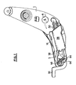
- the tilt adjustment mechanism comprises, in the usual manner, a flange 1 fixed to the seat back which must be adjusted, and a flange 2 fixed to the seat of this same seat.
- the fixed flange 2 comprises a centering pin 4 which is drawn in the thickness of the sheet which constitutes it, that is to say which protrudes on one of the faces of the flange, while a recess is formed on the opposite face.
- the movable flange 1 has, for its part, a hole 6 of diameter similar to that of the pin 4 which is intended, during assembly of the mechanism, to snap onto this pin, as shown in Figure 1.
- the flange 1 also includes a lug 8 cut and pushed outwards, towards the fixed flange 2. This lug immobilizes laterally the corresponding end of the fixed flange 2, which can easily be fitted between it and the movable flange 1 by pivoting around of pawn 4.
- the fixed flange 2 also comprises two curved tabs, respectively 10 and 12, on which a flat pawl 14 having slots 16 and 18, also curved, fits.
- the curvature of the slots 16 and 18 corresponds to that of the tabs 10 and 12 but their length is greater than that of these tabs so that the pawl 14 can slide parallel to itself on the fixed flange 2 while being guided by the tabs 10 and 12 and remaining in contact with the flange 2.
- the pawl 14 also includes a toothed sector 20 which is capable of engaging with a toothing 22 carried by the extreme edge of the movable flange.
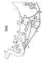
- the teeth 20 and 22 have corresponding curvatures, so that they can mesh in all the angular positions of one or the other of these two members. Thanks to the clearance provided between the tabs 10, 12 and the slots 16, 18, the pawl 14 can thus be locked on the flange 1 (fig. 4) or away from the teeth 22 of this flange, as shown in FIG. 5 .
- the pawl 14 is extended by a hook 24 which cooperates with the spout 26 of a cam 28 formed at the end of a control lever 30.
- the lever 30 comprises, substantially in the center of the cam 28, a hole 32 which allows it to be fitted onto a pivot pin 34 secured to the flange 2 and, preferably, drawn in the thickness of this flange.
- the cam 28 also comprises a curved surface 36 which comes into contact with a ramp 38, of corresponding shape, of the pawl 14 in the locking position of the lever 30 shown in FIG. 4. In this position, in fact, the spout 26 of the cam 28 is released from the hook 24, while the surface 36 presses on the ramp 38 to push the pawl 14 against the teeth 22 and lock the flange 1.
- the movable flange 1 also comprises a hole 40 which, during assembly, is located opposite a curved opening 42 of the fixed flange 2, the opening 42 being centered on the pivot axis of the flange 1, that is to say that is to say on the axis of the centering pin 4.
- a bent tube 44 is introduced into the hole 40, so as to penetrate inside the lumen 42.
- the tube 44 is immobilized relative to the movable flange 1 grage à two pairs of diametrically opposite lugs, respectively 46 and 48, axially spaced on this tube but offset from one another.
- the pins 46 closest to the end of the tube 44 pass through lateral extensions 47 of the hole 40, while the pins 48 are stopped by the wall of this hole, as clearly shown in Figures 4 and 5 On which the tube 44 has been shown in the open position to facilitate understanding of the drawing.
- the dimension of the lugs 46 is however such that they can move in the lumen 42 during the pivoting of the flange 1.
- the length of the lumen 42 therefore regulates the angle by which this flange 1 can pivot.
- a helical spring 50 which is in abutment, at one end on a flange 52 of the tube and, at its opposite end, on lugs 54 carried by the end of a housing 56 (fig. 1 and 2).
- the housing 56 which has a general U-shape, is provided with lugs 58 intended to penetrate into slots 60, 62 formed in the flange 2, on the one hand in the vicinity of its end opposite to the flange 1, and on the other hand near this flange 1.
- the housing 56 extends above the various parts of the mechanism and the same applies to the spring 50.
- This spring is thus tensioned between the flange 1 and the housing 56.
- the latter applies the cam 28 of the lever 30, as well as the pawl 14, against the fixed flange 2.
- the spring 50 also pushes the housing 56 against this same flange while the housing provides external protection for the assembly. .
- the spring 50 being fixed on the flange 52 of the tube 44, which is mounted in a hole 40 drilled in the vicinity of the teeth 22 and the outer edge of the flange, exerts a pressure permanently on the base of the movable flange 1 which tends to straighten the back, secured to this flange, in the vertical position.
- the housing 56 is extended, beyond the lugs 54 for supporting the spring 50, by arms 64 which are each terminated by a lug 58, and at least one of which is pierced with a hole 65 for fixing the end of a small spring 66, the opposite end of which is hooked to a fork 68 projecting laterally on the arm 30 (fig. L and 5).
- the spring 66 pulls the fork 68 towards the housing 56 and the lever 30 towards the locking position shown in FIG. 4, which causes the pawl 14 to slide along the guide tabs 10 and 12 and ensures the locking of the flange 1 and, consequently, the backrest in the chosen position.
- a simple effort on the lever 30 against the action of this spring 66 however makes it possible to release the flange 1 and to modify the inclination of the backrest, the lever 30 automatically resuming the locking position as soon as it is released.
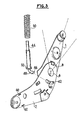
- the flanges 1 and 2 are first joined by fitting the pin 4 into the hole 6 of the flange 1, then by rotating the two flanges to slide the edge of the flange 2 under the tab 8 (fig. 3).
- the pawl 14 is placed on the flange 2, its slots 16, 18, fitting onto the curved tabs 10 and 12 which center it exactly in transverse direction allowing it a limited longitudinal displacement.
- the lever 30 is then mounted on the pin 34, so that the cam 28 is positioned opposite the hook 24.
Landscapes
- Engineering & Computer Science (AREA)
- Aviation & Aerospace Engineering (AREA)
- Transportation (AREA)
- Mechanical Engineering (AREA)
- Chairs For Special Purposes, Such As Reclining Chairs (AREA)
- Seats For Vehicles (AREA)
Applications Claiming Priority (2)
| Application Number | Priority Date | Filing Date | Title |
|---|---|---|---|
| FR8318225 | 1983-11-16 | ||
| FR8318225A FR2554695B1 (fr) | 1983-11-16 | 1983-11-16 | Mecanisme d'inclinaison pour siege, et notamment pour siege d'automobile |
Publications (2)
| Publication Number | Publication Date |
|---|---|
| EP0142428A1 true EP0142428A1 (de) | 1985-05-22 |
| EP0142428B1 EP0142428B1 (de) | 1986-10-15 |
Family
ID=9294181
Family Applications (1)
| Application Number | Title | Priority Date | Filing Date |
|---|---|---|---|
| EP84402229A Expired EP0142428B1 (de) | 1983-11-16 | 1984-11-06 | Neigungsvorrichtung für Sitze, insbesondere für Kraftwagensitze |
Country Status (8)
| Country | Link |
|---|---|
| US (1) | US4645263A (de) |
| EP (1) | EP0142428B1 (de) |
| JP (1) | JPS60174110A (de) |
| CA (1) | CA1235995A (de) |
| DE (1) | DE3460949D1 (de) |
| ES (1) | ES282883Y (de) |
| FR (1) | FR2554695B1 (de) |
| ZA (1) | ZA848859B (de) |
Cited By (1)
| Publication number | Priority date | Publication date | Assignee | Title |
|---|---|---|---|---|
| GB2269986A (en) * | 1992-07-30 | 1994-03-02 | Flight Equip & Eng | Vehicle seats |
Families Citing this family (11)
| Publication number | Priority date | Publication date | Assignee | Title |
|---|---|---|---|---|
| US5091053A (en) * | 1990-02-28 | 1992-02-25 | At&T Bell Laboratories | Matte finishes on optical fibers and other glass articles |
| US5138744A (en) * | 1991-03-13 | 1992-08-18 | Bertrand Faure Ltd. | Zero chuck recliner with floating pawl |
| US6161899A (en) * | 1998-08-18 | 2000-12-19 | Fisher Dynamics Corporation | Seatback latch mechanism with locking pin |
| US6290297B1 (en) | 1998-08-18 | 2001-09-18 | Fisher Dynamics Corporation | Latch assembly and seat hinge with interlock |
| US6550864B1 (en) * | 1998-08-18 | 2003-04-22 | Fisher Dynamics Corporation | Seatback latch mechanism with pivoting locking pin |
| RU2216460C2 (ru) * | 2000-11-23 | 2003-11-20 | Федеральное государственное унитарное предприятие "Производственное объединение "Ульяновский машиностроительный завод" | Устройство для регулирования относительного положения спинки и подушки сиденья транспортного средства |
| JP3833936B2 (ja) * | 2001-12-25 | 2006-10-18 | アイシン精機株式会社 | シート装置 |
| DE102004038999B4 (de) * | 2004-08-10 | 2010-09-30 | Johnson Controls Gmbh | Verstellvorrichtung, insbesondere für einen Sitz und Verfahren zur Montage einer Verstellvorrichtung für einen Sitz für ein Kraftfahrzeug |
| CN106515521B (zh) * | 2016-12-06 | 2019-06-28 | 浙江天成自控股份有限公司 | 具有辅助锁紧结构的座椅调角器 |
| US11370332B2 (en) | 2020-06-19 | 2022-06-28 | Fisher & Company, Incorporated | Latch mechanism for seat assembly |
| US12662024B2 (en) | 2023-10-19 | 2026-06-23 | Fisher & Company, Incorporated | Clip for vehicle seat cable assembly |
Citations (2)
| Publication number | Priority date | Publication date | Assignee | Title |
|---|---|---|---|---|
| FR2377175A1 (fr) * | 1977-01-13 | 1978-08-11 | Faure Bertrand | Perfectionnements aux articulations de siege |
| FR2420319A1 (fr) * | 1978-03-23 | 1979-10-19 | Rockwell International Corp | Mecanisme de reglage pour siege inclinable, notamment pour vehicule |
Family Cites Families (10)
| Publication number | Priority date | Publication date | Assignee | Title |
|---|---|---|---|---|
| US2336013A (en) * | 1940-03-07 | 1943-12-07 | American Seating Co | Chair |
| DE1239951B (de) * | 1961-12-07 | 1967-05-03 | Recaro G M B H & Co | Gelenkbeschlag fuer Sitze mit verstellbarer Lehne, insbesondere fuer Kraftfahrzeuge |
| JPS5116708Y2 (de) * | 1971-06-10 | 1976-05-06 | ||
| DE2232117C3 (de) * | 1972-06-30 | 1980-10-02 | Bremshey Ag, 5650 Solingen | Höhen- und neigungsverstellbarer Fahrzeugsitz |
| US4178037A (en) * | 1975-02-26 | 1979-12-11 | Ferro Manufacturing Corporation | Seat recliner assembly |
| GB1513822A (en) * | 1975-03-04 | 1978-06-14 | Parnall & Sons Ltd | Backrest adjustment mechanism for chairs |
| GB1536104A (en) * | 1976-05-28 | 1978-12-20 | Brugger Metalcraft | Seat adjusting mechanism |
| US4165900A (en) * | 1977-02-28 | 1979-08-28 | J. C. Sales & Mfg., Inc. | Reclinable seating structures |
| US4223946A (en) * | 1978-09-25 | 1980-09-23 | Keiper Automobiltechnik Gmbh & Co. Kg | Vehicle seat fitting |
| JPS6124105Y2 (de) * | 1980-02-08 | 1986-07-19 |
-
1983
- 1983-11-16 FR FR8318225A patent/FR2554695B1/fr not_active Expired
-
1984
- 1984-11-06 EP EP84402229A patent/EP0142428B1/de not_active Expired
- 1984-11-06 DE DE8484402229T patent/DE3460949D1/de not_active Expired
- 1984-11-06 US US06/668,924 patent/US4645263A/en not_active Expired - Fee Related
- 1984-11-13 ES ES1984282883U patent/ES282883Y/es not_active Expired
- 1984-11-14 ZA ZA848859A patent/ZA848859B/xx unknown
- 1984-11-15 CA CA000467876A patent/CA1235995A/en not_active Expired
- 1984-11-16 JP JP59242213A patent/JPS60174110A/ja active Granted
Patent Citations (2)
| Publication number | Priority date | Publication date | Assignee | Title |
|---|---|---|---|---|
| FR2377175A1 (fr) * | 1977-01-13 | 1978-08-11 | Faure Bertrand | Perfectionnements aux articulations de siege |
| FR2420319A1 (fr) * | 1978-03-23 | 1979-10-19 | Rockwell International Corp | Mecanisme de reglage pour siege inclinable, notamment pour vehicule |
Cited By (2)
| Publication number | Priority date | Publication date | Assignee | Title |
|---|---|---|---|---|
| GB2269986A (en) * | 1992-07-30 | 1994-03-02 | Flight Equip & Eng | Vehicle seats |
| GB2269986B (en) * | 1992-07-30 | 1997-03-19 | Flight Equip & Eng | Vehicle seats |
Also Published As
| Publication number | Publication date |
|---|---|
| JPS60174110A (ja) | 1985-09-07 |
| EP0142428B1 (de) | 1986-10-15 |
| US4645263A (en) | 1987-02-24 |
| DE3460949D1 (en) | 1986-11-20 |
| ES282883U (es) | 1985-04-16 |
| FR2554695B1 (fr) | 1986-03-28 |
| JPH0366883B2 (de) | 1991-10-21 |
| ES282883Y (es) | 1985-11-16 |
| ZA848859B (en) | 1985-07-31 |
| CA1235995A (en) | 1988-05-03 |
| FR2554695A1 (fr) | 1985-05-17 |
Similar Documents
| Publication | Publication Date | Title |
|---|---|---|
| EP0024976B1 (de) | Vorrichtung zum Regeln der relativen Neigung zweier Teile, insbesondere der zwei Teile eines Fahrzeugsitzes | |
| EP0142428B1 (de) | Neigungsvorrichtung für Sitze, insbesondere für Kraftwagensitze | |
| EP0348276B1 (de) | Zentrale schwenkbare Armlehne für Kraftfahrzeugsitze | |
| FR2853597A1 (fr) | Glissiere pour siege de vehicule automobile | |
| EP0949111B1 (de) | Modulares Befestigungssystem mit Nockensteuerung | |
| EP0205379B1 (de) | Schloss, insbesondere für Sicherheitsgurte | |
| EP0078203A1 (de) | Sicherheitsgurtaufwickelautomat | |
| EP0069626B1 (de) | Einrichtung für die Montage einer Umschaltvorrichtung an einem Fahrradrahmen | |
| EP0211718B1 (de) | Schloss, insbesondere für Sicherheitsgurte in Kraftfahrzeugen | |
| EP0064925B1 (de) | Verriegelungsvorrichtung eines unterhalb eines Fahrzeugbodens angebrachten Ersatzradträgers | |
| EP0592341B1 (de) | Verbesserung an Türgriffen mit einer plattenförmigen Handhabe | |
| FR2765532A1 (fr) | Systeme d'articulation d'un element rabattable de siege arriere sur un vehicule automobile | |
| FR2656858A1 (fr) | Structure unitaire deplacable de calage ou de soutien d'un vehicule routier par ses roues. | |
| FR3017570A1 (fr) | Dispositif de reglage en hauteur d'un appuie-tete de siege de vehicule automobile | |
| EP3350016B1 (de) | Verriegelungsvorrichtung für zwei positionen einer hintersitz-rückenlehne eines kraftfahrzeugs | |
| EP0245131B1 (de) | Antriebsvorrichtung zum schrittweisen Verstellen eines Teiles und insbesondere der Rückenlehne eines Fahrzeugsitzes | |
| EP0972143A1 (de) | Kupplungsmechanismus mit einer nachstellvorrichtungseinheit | |
| EP1024049B1 (de) | Selektive Vorrichtung zum drehbaren Verbinden für zwei relativ zueinander rotierenderTeile | |
| EP0218517B1 (de) | Schloss, insbesondere für Sicherheitsgurte in Kraftfahrzeugen | |
| EP1293371B1 (de) | Verbindungsanordnung und entsprechendes Kraftfahrzeug | |
| FR2730264A1 (fr) | Ensemble de plaques et poignees de porte comportant un dispositif de rappel en position de la poignee | |
| EP3320818B1 (de) | Vorrichtung zur behandlung von lebensmitteln, die mit einem befestigungssystem für ein werkzeug ausgestattet ist | |
| FR2706409A1 (fr) | Dispositif d'accrochage réversible d'un siège sur un plancher de véhicule automobile. | |
| FR2892356A1 (fr) | Mecanisme d'articulation, son procede de fabrication et siege de vehicule comportant un tel mecanisme. | |
| FR2771147A1 (fr) | Frein a disque a etrier flottant a une seule colonnette |
Legal Events
| Date | Code | Title | Description |
|---|---|---|---|
| PUAI | Public reference made under article 153(3) epc to a published international application that has entered the european phase |
Free format text: ORIGINAL CODE: 0009012 |
|
| AK | Designated contracting states |
Designated state(s): BE DE GB IT LU NL SE |
|
| 17P | Request for examination filed |
Effective date: 19850507 |
|
| RTI1 | Title (correction) | ||
| GRAA | (expected) grant |
Free format text: ORIGINAL CODE: 0009210 |
|
| AK | Designated contracting states |
Kind code of ref document: B1 Designated state(s): BE DE GB IT LU NL SE |
|
| REF | Corresponds to: |
Ref document number: 3460949 Country of ref document: DE Date of ref document: 19861120 |
|
| PG25 | Lapsed in a contracting state [announced via postgrant information from national office to epo] |
Ref country code: LU Free format text: LAPSE BECAUSE OF NON-PAYMENT OF DUE FEES Effective date: 19861130 |
|
| ITF | It: translation for a ep patent filed | ||
| PLBE | No opposition filed within time limit |
Free format text: ORIGINAL CODE: 0009261 |
|
| STAA | Information on the status of an ep patent application or granted ep patent |
Free format text: STATUS: NO OPPOSITION FILED WITHIN TIME LIMIT |
|
| 26N | No opposition filed | ||
| PGFP | Annual fee paid to national office [announced via postgrant information from national office to epo] |
Ref country code: LU Payment date: 19901105 Year of fee payment: 7 |
|
| PGFP | Annual fee paid to national office [announced via postgrant information from national office to epo] |
Ref country code: BE Payment date: 19901211 Year of fee payment: 7 |
|
| EPTA | Lu: last paid annual fee | ||
| PG25 | Lapsed in a contracting state [announced via postgrant information from national office to epo] |
Ref country code: BE Effective date: 19911130 |
|
| BERE | Be: lapsed |
Owner name: CYCLES PEUGEOT Effective date: 19911130 |
|
| REG | Reference to a national code |
Ref country code: GB Ref legal event code: 732 |
|
| ITTA | It: last paid annual fee | ||
| ITPR | It: changes in ownership of a european patent |
Owner name: CAMBIO RAGIONE SOCIALE;ECIA - EQUIPEMENTS ET COMPO |
|
| NLS | Nl: assignments of ep-patents |
Owner name: ACIERS ET OUTILLAGE PEUGEOT S.A. TE AUDINCOURT, FR |
|
| PGFP | Annual fee paid to national office [announced via postgrant information from national office to epo] |
Ref country code: DE Payment date: 19931020 Year of fee payment: 10 |
|
| PGFP | Annual fee paid to national office [announced via postgrant information from national office to epo] |
Ref country code: GB Payment date: 19931029 Year of fee payment: 10 |
|
| NLT1 | Nl: modifications of names registered in virtue of documents presented to the patent office pursuant to art. 16 a, paragraph 1 |
Owner name: ECIA-EQUIPEMENTS ET COMPOSANTS POUR L'INDUSTRIE AU |
|
| NLS | Nl: assignments of ep-patents |
Owner name: CESA-COMPAGNIE EUROPEENNE DE SIEGES POUR AUTOMOBIL |
|
| PGFP | Annual fee paid to national office [announced via postgrant information from national office to epo] |
Ref country code: SE Payment date: 19931116 Year of fee payment: 10 |
|
| PGFP | Annual fee paid to national office [announced via postgrant information from national office to epo] |
Ref country code: NL Payment date: 19931130 Year of fee payment: 10 |
|
| PG25 | Lapsed in a contracting state [announced via postgrant information from national office to epo] |
Ref country code: GB Effective date: 19941106 |
|
| PG25 | Lapsed in a contracting state [announced via postgrant information from national office to epo] |
Ref country code: SE Effective date: 19941107 |
|
| EAL | Se: european patent in force in sweden |
Ref document number: 84402229.3 |
|
| PG25 | Lapsed in a contracting state [announced via postgrant information from national office to epo] |
Ref country code: NL Effective date: 19950601 |
|
| GBPC | Gb: european patent ceased through non-payment of renewal fee |
Effective date: 19941106 |
|
| NLV4 | Nl: lapsed or anulled due to non-payment of the annual fee | ||
| PG25 | Lapsed in a contracting state [announced via postgrant information from national office to epo] |
Ref country code: DE Effective date: 19950801 |
|
| EUG | Se: european patent has lapsed |
Ref document number: 84402229.3 |