EP0142540B1 - Gliederkette - Google Patents
Gliederkette Download PDFInfo
- Publication number
- EP0142540B1 EP0142540B1 EP84902026A EP84902026A EP0142540B1 EP 0142540 B1 EP0142540 B1 EP 0142540B1 EP 84902026 A EP84902026 A EP 84902026A EP 84902026 A EP84902026 A EP 84902026A EP 0142540 B1 EP0142540 B1 EP 0142540B1
- Authority
- EP
- European Patent Office
- Prior art keywords
- link
- chain
- plane
- section
- cross
- Prior art date
- Legal status (The legal status is an assumption and is not a legal conclusion. Google has not performed a legal analysis and makes no representation as to the accuracy of the status listed.)
- Expired
Links
- 238000005304 joining Methods 0.000 claims abstract description 14
- 230000009467 reduction Effects 0.000 claims description 6
- 241000282327 Felis silvestris Species 0.000 abstract description 5
- 230000002093 peripheral effect Effects 0.000 abstract 1
- 238000005452 bending Methods 0.000 description 18
- 238000010276 construction Methods 0.000 description 4
- 230000000694 effects Effects 0.000 description 4
- 230000006835 compression Effects 0.000 description 3
- 238000007906 compression Methods 0.000 description 3
- 238000009826 distribution Methods 0.000 description 2
- 230000001939 inductive effect Effects 0.000 description 2
- 230000004048 modification Effects 0.000 description 2
- 238000012986 modification Methods 0.000 description 2
- 230000000750 progressive effect Effects 0.000 description 2
- 238000000926 separation method Methods 0.000 description 2
- 229910000851 Alloy steel Inorganic materials 0.000 description 1
- 241000237503 Pectinidae Species 0.000 description 1
- 230000004075 alteration Effects 0.000 description 1
- 238000005266 casting Methods 0.000 description 1
- 230000005489 elastic deformation Effects 0.000 description 1
- 238000005242 forging Methods 0.000 description 1
- 238000004519 manufacturing process Methods 0.000 description 1
- 238000000034 method Methods 0.000 description 1
- 230000007935 neutral effect Effects 0.000 description 1
- 238000007747 plating Methods 0.000 description 1
- 238000005381 potential energy Methods 0.000 description 1
- 235000020637 scallop Nutrition 0.000 description 1
- 238000003892 spreading Methods 0.000 description 1
- 230000007480 spreading Effects 0.000 description 1
- 238000003466 welding Methods 0.000 description 1
Images




Classifications
-
- F—MECHANICAL ENGINEERING; LIGHTING; HEATING; WEAPONS; BLASTING
- F16—ENGINEERING ELEMENTS AND UNITS; GENERAL MEASURES FOR PRODUCING AND MAINTAINING EFFECTIVE FUNCTIONING OF MACHINES OR INSTALLATIONS; THERMAL INSULATION IN GENERAL
- F16G—BELTS, CABLES, OR ROPES, PREDOMINANTLY USED FOR DRIVING PURPOSES; CHAINS; FITTINGS PREDOMINANTLY USED THEREFOR
- F16G13/00—Chains
- F16G13/12—Hauling- or hoisting-chains so called ornamental chains
Definitions
- the present invention relates to link chain made up of interconnecting links of opposed U-form.
- link chain is well known and generally has double curvature surfaces for transferring load from link to link.
- This link chain most commonly has its links manufactured from uniform (e.g. round) bar by bending the bar into opposed U-form and welding the adjacent ends of the bent bar to form a substantially elliptical link.
- a central strut known as a "stud" is often provided at the minor diameter of the ellipse to strengthen the link.
- the links of these prior art chains therefore have a substantially circular limb cross section; and these prior art chains are generally deployed around pocketed driving wheels (wildcats) and curved surfaces such as ships stems and hawsepipe knuckles despite high bending stresses arising in particular links when in a pocketed driving or idling wheel and when a link of the chain is supported at a centrally located fulcrum when the chain is stretched; taut around a curved surface of relatively large radius and under substantial load.
- pocketed driving wheels wildcats
- curved surfaces such as ships stems and hawsepipe knuckles
- each alternate link In a pocketed wheel, each alternate link is supported at its shoulders while lying flat in a pocket and load is applied to it by the next link pivoting freely on it in a groove in the wheel at right angles to the bottom of the pocket.
- the uniform round bar of the link does not provide the best shape, orientation, and position of sections to minimise and bear these induced bending stresses.
- a link for link chain is shown in DE-C-922386 comprising C-shaped ends connected by joining limb portions and the link is formed such that its external profile as viewed in the plane of the link is of waisted form at said joining limb portions.
- This waisted form construction of the link can assist in reducing the stress loading in the link when the link chain is stretched taut round curved surfaces, e.g. at ship sterns or hawsepipe knuckles.
- U.S.-A-3864906 discloses links for chains wherein the section modulus about an axis perpendicular to the plane of the link for cross-sections at the link shoulders is greater than the corresponding section modulus at the joining limb portions of the link, and this arrangement can provide at improved stress distribution in the link when the link chain is under load.
- section modulus about an axis perpendicular to the plane of the link of cross-sections of each shoulder at the links C-shaped ends greater than the corresponding section modulus of a cross-section of the corresponding central crown portion at the C-shaped ends.
- the depth of the above cross-sections measured in the plane of the link is greater at each shoulder than at the crown and at the joining time portions.
- the above cross-sections at the crown and shoulder comprise opposed arcuate parts the radius of curvature of one of said arcuate parts being substantially greater than the radius of curvature of the other part.
- the central stud is rectangular in section with a minimum dimension of stud cross-section in the plane of the link.
- chain-cable includes a series of interlinked stud links 1 each of which is symmetrical relative to a mid-transverse axis YY of the link, each link 1 comprising C-form ends 2 joined by limb portions 3 with a central stud 4 at the limb portions 3; there is thus provided a pair of spaced apertures 5 through which adjacent links pass.
- Each C-form end 2 includes a crown portion 6 and shoulder portions 7 adjacent the crown portion.
- the links 1 can be made of alloy steel and the exemplary link is designated 76 mm.
- the cross section of the link 1 at the crown portion 6 approximates to an elliptic form (see Fig. 2) and has an arcuate outer surface O and an arcuate inner surface I joined to the outer surface 0 by side surfaces T, the outer surface 0 having a radius R o greater than the radius R, of the inner surface I.
- the radius R o increases substantially in the shoulder portions 7, but in the limb portions 3 the outer surfaces 0 have considerably scalloped sides 8, (see Figs. 3 and 9), the tangent to the scalloped sides 8 making an angle of approximately 43° to the plane of the link, i.e. the mid-longitudinal plane XY.
- the outer surfaces O of the limb portions 3 are of a waisted form (see Fig. 1) in side view so that the width W 1 of the link at the mid section K-K (Fig. 3) is substantially less than the links maximum width W 2 which occurs at the section G-G (Fig. 7).
- W1/W2 0.85 but other ratios are possible e.g. the ratio may be as high as 0.97 or as low as 0.75 for operating on cylindrical surfaces of radii 20D to 1.5D.
- the benefits of this waisted construction will be appreciated from a consideration of Fig. 10 which shows the chain of Fig. 1 passing around a cylinder 11.
- the bending moment arm V defined by the distance from each point of contact S l , S 2 to the plane XY of an adjacent link is less than the corresponding bending moment arm V 2 of the prior art link shown in Fig. 12.
- scalloped sides B of the limb portions 3 permit the link to rotate about its longitudinal axis x-x while in contact with a cylindrical surface having a radius R,3.1 D so that no point loading on a fulcrum will occur at the center of the link. Also, the scalloping is sufficient to allow up to 4° splaying of the links beyond the 90° to each other when wrapped around and in contact with a cylindrical surface.
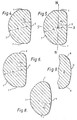
- the shoulder portions 7 have a greater section depth, section area and section modulus than the crown portions 6. It can be seen in Figs. 4-6 that the shoulder sections illustrated in these figures have a greater depth and area than the central crown section AA of Fig. 2 and the mid-transverse plane section KK of Fig. 3. Referring to Fig. 1, the following table sets out the area, depth (direction S-S, see Fig. 5) and section modulus (about transverse axis N-N through centroid) of sections AA to KK indicated in Fig. 1 in terms of a ratio with the pertinent value at section D-D (indicated as unity in the table):
- section DD reduces bending stresses at the shoulders 7 where high stress concentration is known to be present in round-bar stud-link chains. Further, the progressive reduction of section modulus towards the crown encourages the crown portion 6 to "wrap round" the crown of the next adjacent link under load both to limit the flexure and, hence, stresses in the crown 6 and to spread the load over the crown portion and so reduce the moment arm inducing bending stresses in the shoulders 7.
- the relatively low section moduli of the sections of the joining limbs 3 over the considerable distance between section GG and KK allow flexing to occur without unacceptably high stress concentration.
- the deepening of the sections at the shoulders 7 serves also to reduce the eccentricity between load application and support points in links lying flat in the pockets of driving and idling wheels and so reduce the high bending stresses induced by passage over such wheels.
- the limb portions on either side of a common aperture 5 converge slightly towards the transverse mid-plane.
- the effect of this is that when the link is under tension, greatly reduced compression forces occur in the stud 4.
- This is in contrast to the conventional elliptical link where the corresponding limb portions diverge with the result that very high compression forces occur in the stud when the link is under tension.
- the stud 4 can be of considerably reduced size, and this provides a saving in mass.
- the above link 1 of the present invention can have a mass reduction of approximately 20% over corresponding conventional stud links (round bar)-the present 76 mm link should have a mass of about 32 Kg compared to 40.5 Kg for the round bar link.
- a particularly significant feature of the above chain cable using the links 1 is that it can fully replace a corresponding conventional chain cable without the need for alteration in the existing chain handling equipment.
- the chain cable with links 1 has the following further features:
- the links can be made by a casting operation, but can also be made by forging for example using the techniques described in GB-A-353 131; GB-A-730 811 and GB-A-822 241.
- the cross-sections of the link could be of some other form than those shown.
- the present invention encompasses a "waisted" form link where the link has cross sections of substantially circular form.
- the inner surface of the crown has a flattened portion as shown dashed in Fig.
- Fig. 1 shows the chain link waisted as viewed at right angles to the plane of the link XY
- the link it would be possible for the link to be arranged such that the waisting effect is present when the link is viewed at an angle in the range of 40° to 90° to the plane of the link, even although the link is not so waisted when viewed at right angles to the plane XY.
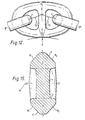
- Figs. 14 and 15 show this alternative construction: when the link of Fig. 15 is viewed in the direction of arrow OV a waisting effect will be apparent by virtue of the diagonally disposed scallops 8 1 and 8 2 .
- the cross sectional area at the waisted path is maintained roughly equal to that of the link of Fig. 1 (for 76 mm link): this results in the sides of the apertures 5 being of slightly diverging form as will be apparent in Fig. 14 whereby the stud 4 becomes subject to higher compressive loads.
- Fig. 13 shows the chain of Fig. 1 supported on a cylindrical surface 11 having a radius of 3.1 D and at an oblique angle to the surface, i.e. the mid transverse axis Y-Y is oblique to the centre line (not shown) of the cylindrical surface 11: the scalloped portion 8 enables the supported chain link to "wrap round" the cylindrical surface.
- the chain of Figs. 14, 15 will be supported in a similar manner as in Fig. 13 when the chain links are arranged in oblique fashion as shown.
Landscapes
- Engineering & Computer Science (AREA)
- General Engineering & Computer Science (AREA)
- Mechanical Engineering (AREA)
- Information Retrieval, Db Structures And Fs Structures Therefor (AREA)
- Tires In General (AREA)
- Transmissions By Endless Flexible Members (AREA)
- Navigation (AREA)
- Devices For Conveying Motion By Means Of Endless Flexible Members (AREA)
- Chain Conveyers (AREA)
- Dry Shavers And Clippers (AREA)
- Eye Examination Apparatus (AREA)
- Vehicle Body Suspensions (AREA)
- Transmission Devices (AREA)
- Flexible Shafts (AREA)
Claims (11)
Applications Claiming Priority (2)
| Application Number | Priority Date | Filing Date | Title |
|---|---|---|---|
| GB838312251A GB8312251D0 (en) | 1983-05-05 | 1983-05-05 | Link chain |
| GB8312251 | 1983-05-05 |
Publications (2)
| Publication Number | Publication Date |
|---|---|
| EP0142540A1 EP0142540A1 (de) | 1985-05-29 |
| EP0142540B1 true EP0142540B1 (de) | 1988-07-27 |
Family
ID=10542179
Family Applications (1)
| Application Number | Title | Priority Date | Filing Date |
|---|---|---|---|
| EP84902026A Expired EP0142540B1 (de) | 1983-05-05 | 1984-05-08 | Gliederkette |
Country Status (16)
| Country | Link |
|---|---|
| US (1) | US4627232A (de) |
| EP (1) | EP0142540B1 (de) |
| JP (1) | JPS60501513A (de) |
| KR (1) | KR880004264Y1 (de) |
| AU (1) | AU2862384A (de) |
| CA (1) | CA1229735A (de) |
| DE (1) | DE3473017D1 (de) |
| ES (1) | ES288806Y (de) |
| FI (1) | FI76411C (de) |
| GB (1) | GB8312251D0 (de) |
| IE (1) | IE55090B1 (de) |
| IT (2) | IT8421707V0 (de) |
| NO (1) | NO172816C (de) |
| NZ (1) | NZ208057A (de) |
| PT (1) | PT78551B (de) |
| WO (1) | WO1984004370A1 (de) |
Families Citing this family (18)
| Publication number | Priority date | Publication date | Assignee | Title |
|---|---|---|---|---|
| US6006514A (en) * | 1997-08-08 | 1999-12-28 | J.O. Bernt & Associates Limited | Link-shape and chain link assembly method |
| US5934062A (en) * | 1997-08-08 | 1999-08-10 | J.O. Bernt & Associates Limited | Link shape and chain link assembly method |
| DE10039565A1 (de) * | 2000-08-09 | 2002-03-07 | Rud Ketten Rieger & Dietz | Kette, Kettenrad und Kettentrieb für ein Hebezeug |
| GB2373560B (en) * | 2001-03-23 | 2005-04-20 | Parsons Chain Company Ltd | Chains |
| DE50206337D1 (de) * | 2001-10-30 | 2006-05-18 | Rud Ketten Rieger & Dietz | Kette, insbesondere hebezeugkette |
| DE10348491C5 (de) * | 2003-10-18 | 2014-07-31 | J. D. Theile Gmbh & Co. Kg | Rundstahlgliederkette |
| USD532025S1 (en) * | 2005-01-26 | 2006-11-14 | Eric Wettlaufer | Drive chain link with cruciform adornment |
| DE102006030984B4 (de) * | 2005-08-17 | 2016-08-04 | Caterpillar Global Mining Europe Gmbh | Kettenantriebs- oder Umlenkanordnung sowie dabei eingesetztes Kettenband |
| US7389634B1 (en) * | 2007-03-22 | 2008-06-24 | Columbus Mckinnon Corporation | Link chain |
| DE102007043744A1 (de) * | 2007-09-04 | 2009-03-05 | Erlau Ag | Gliederverband für eine Reifenkette sowie Stegglied für den Einsatz in einem solchen Gliederverband |
| DE102008034360C5 (de) * | 2008-07-23 | 2020-03-05 | Pewag Austria Gmbh | Aus einem D-Profilstahlabschnitt hergestelltes Kettenglied, insbesondere für eine Hebezeugkette |
| USD604143S1 (en) * | 2008-08-26 | 2009-11-17 | General Pneumatics Corp. | Link |
| US7743597B2 (en) * | 2008-08-26 | 2010-06-29 | General Pneumatics Corp. | Marine safety device attachment with automatic release capability |
| US8074438B2 (en) * | 2009-10-19 | 2011-12-13 | Joy Mm Delaware, Inc. | Link chain |
| DE102010040495A1 (de) | 2010-09-09 | 2012-03-15 | Siemens Aktiengesellschaft | Vorrichtung zum Übertragen einer Kraft, insbesondere Trageschlaufe |
| WO2012119613A1 (de) * | 2011-03-07 | 2012-09-13 | Pewag Austria Gmbh | Aus ovalen profilkettengliedern bestehende kette und verfahren zur herstellung einer solchen |
| DE102011050425B4 (de) * | 2011-05-17 | 2019-03-28 | Thiele Gmbh & Co. Kg | Rundstahlkette |
| USD790138S1 (en) * | 2016-09-01 | 2017-06-20 | Feline Environmental Enrichment Design Company, Llc | Pet feeding device |
Family Cites Families (10)
| Publication number | Priority date | Publication date | Assignee | Title |
|---|---|---|---|---|
| US1806733A (en) * | 1931-05-26 | Signors to acme pishing tool co | ||
| DE48417C (de) * | c. hoppe in Berlin N., Gartenstrafse 9 | Ringkette mit in der Ringmitte abgeflachten Gliedern | ||
| US2103972A (en) * | 1936-10-12 | 1937-12-28 | American Brake Shoe & Foundry | Heavy duty abrasion resisting chain |
| DE922386C (de) * | 1945-01-13 | 1955-01-13 | Gutehoffnungshuette Sterkrade | Kettenglied fuer hohe Dauerbeanspruchung |
| US2650470A (en) * | 1949-12-09 | 1953-09-01 | Charles E Sennholtz | Chain link |
| US3014340A (en) * | 1958-02-20 | 1961-12-26 | Konink Nl Grofsmederij Nv | Chain having alternate links with inserted studs and means to inhibit loosening of said studs |
| US3662539A (en) * | 1968-10-16 | 1972-05-16 | Peter Florjancic | Injection moulded chain, especially plastic chain |
| US3744239A (en) * | 1971-12-20 | 1973-07-10 | T Anson | Chain link with extended wear surface |
| US3864906A (en) * | 1973-06-22 | 1975-02-11 | Vickers Ruwolt Pty Ltd | Chain link |
| JPS58501684A (ja) * | 1981-10-07 | 1983-10-06 | パ−ソンス コントロ−ルス リミテツド | 長伸び型主リンク |
-
1983
- 1983-05-05 GB GB838312251A patent/GB8312251D0/en active Pending
-
1984
- 1984-05-03 IE IE1098/84A patent/IE55090B1/en unknown
- 1984-05-03 CA CA000453501A patent/CA1229735A/en not_active Expired
- 1984-05-04 PT PT78551A patent/PT78551B/pt unknown
- 1984-05-04 ES ES1984288806U patent/ES288806Y/es not_active Expired
- 1984-05-04 NZ NZ208057A patent/NZ208057A/en unknown
- 1984-05-07 KR KR2019840004233U patent/KR880004264Y1/ko not_active Expired
- 1984-05-07 IT IT8421707U patent/IT8421707V0/it unknown
- 1984-05-07 IT IT8420827A patent/IT1213164B/it active
- 1984-05-08 WO PCT/GB1984/000154 patent/WO1984004370A1/en not_active Ceased
- 1984-05-08 DE DE8484902026T patent/DE3473017D1/de not_active Expired
- 1984-05-08 US US06/690,492 patent/US4627232A/en not_active Expired - Fee Related
- 1984-05-08 JP JP59501876A patent/JPS60501513A/ja active Pending
- 1984-05-08 EP EP84902026A patent/EP0142540B1/de not_active Expired
- 1984-05-08 AU AU28623/84A patent/AU2862384A/en not_active Abandoned
-
1985
- 1985-01-02 FI FI850015A patent/FI76411C/fi not_active IP Right Cessation
- 1985-01-04 NO NO85850038A patent/NO172816C/no unknown
Also Published As
| Publication number | Publication date |
|---|---|
| ES288806U (es) | 1987-11-01 |
| IT1213164B (it) | 1989-12-14 |
| JPS60501513A (ja) | 1985-09-12 |
| US4627232A (en) | 1986-12-09 |
| FI850015L (fi) | 1985-01-02 |
| IE841098L (en) | 1984-11-05 |
| GB8312251D0 (en) | 1983-06-08 |
| CA1229735A (en) | 1987-12-01 |
| KR880004264Y1 (ko) | 1988-11-30 |
| KR840006286U (ko) | 1984-12-03 |
| PT78551B (en) | 1986-08-08 |
| EP0142540A1 (de) | 1985-05-29 |
| WO1984004370A1 (en) | 1984-11-08 |
| IE55090B1 (en) | 1990-05-23 |
| IT8420827A0 (it) | 1984-05-07 |
| IT8421707V0 (it) | 1984-05-07 |
| NZ208057A (en) | 1986-02-21 |
| PT78551A (en) | 1984-06-01 |
| ES288806Y (es) | 1988-05-16 |
| FI76411C (fi) | 1988-10-10 |
| FI76411B (fi) | 1988-06-30 |
| NO172816B (no) | 1993-06-01 |
| AU2862384A (en) | 1984-11-19 |
| NO850038L (no) | 1985-01-04 |
| FI850015A0 (fi) | 1985-01-02 |
| DE3473017D1 (en) | 1988-09-01 |
| NO172816C (no) | 1993-09-08 |
Similar Documents
| Publication | Publication Date | Title |
|---|---|---|
| US4627232A (en) | Link chain | |
| US5372554A (en) | Rocker joint chain with crescent shaped apertures | |
| US5464374A (en) | Chain having improved load distribution | |
| US4104871A (en) | Energy conducting chain | |
| EP0385681B1 (de) | Kraftübertragungskette | |
| US3718945A (en) | Slings, tow-ropes and the like | |
| US4845814A (en) | Wedge socket | |
| US3224185A (en) | Link and shackle insert | |
| US6186921B1 (en) | Rocker joint silent chain having a joint pin thicker than a corresponding rocker pin | |
| US5176587A (en) | Single pin rocker joint bushing chain | |
| JPH09196126A (ja) | サイレントチェーン | |
| US4498284A (en) | Chain link | |
| JPS58501684A (ja) | 長伸び型主リンク | |
| US5562559A (en) | Rocker joint chain with crescent shaped aperture | |
| US5334111A (en) | Single pin rocker joint CVT chain | |
| CA1048794A (en) | Link chain | |
| US5192253A (en) | Single pin rocker joint chain | |
| CA1147562A (en) | Chain link construction | |
| CA1052541A (en) | Connector link | |
| US4579550A (en) | Chains for continuously variable conical pulley transmissions | |
| JPH0535771B2 (de) | ||
| RU2078266C1 (ru) | Соединительное звено круглозвенной цепи | |
| USH518H (en) | End constraints for torsion members | |
| SU745380A3 (ru) | Шарнирна цепь | |
| JPH07189147A (ja) | スチールコード及びこのスチールコードを用いたゴム複合体 |
Legal Events
| Date | Code | Title | Description |
|---|---|---|---|
| PUAI | Public reference made under article 153(3) epc to a published international application that has entered the european phase |
Free format text: ORIGINAL CODE: 0009012 |
|
| AK | Designated contracting states |
Designated state(s): DE FR GB LU NL SE |
|
| 17P | Request for examination filed |
Effective date: 19850502 |
|
| 17Q | First examination report despatched |
Effective date: 19860227 |
|
| GRAA | (expected) grant |
Free format text: ORIGINAL CODE: 0009210 |
|
| AK | Designated contracting states |
Kind code of ref document: B1 Designated state(s): DE FR GB LU NL SE |
|
| REF | Corresponds to: |
Ref document number: 3473017 Country of ref document: DE Date of ref document: 19880901 |
|
| ET | Fr: translation filed | ||
| PLBI | Opposition filed |
Free format text: ORIGINAL CODE: 0009260 |
|
| PG25 | Lapsed in a contracting state [announced via postgrant information from national office to epo] |
Ref country code: LU Free format text: LAPSE BECAUSE OF NON-PAYMENT OF DUE FEES Effective date: 19890531 |
|
| 26 | Opposition filed |
Opponent name: FIRMA AUGUST THIELE Effective date: 19890407 |
|
| NLR1 | Nl: opposition has been filed with the epo |
Opponent name: FIRMA AUGUST THIELE |
|
| PLBM | Termination of opposition procedure: date of legal effect published |
Free format text: ORIGINAL CODE: 0009276 |
|
| STAA | Information on the status of an ep patent application or granted ep patent |
Free format text: STATUS: OPPOSITION PROCEDURE CLOSED |
|
| 27C | Opposition proceedings terminated |
Effective date: 19900301 |
|
| PGFP | Annual fee paid to national office [announced via postgrant information from national office to epo] |
Ref country code: GB Payment date: 19930505 Year of fee payment: 10 |
|
| PGFP | Annual fee paid to national office [announced via postgrant information from national office to epo] |
Ref country code: SE Payment date: 19930526 Year of fee payment: 10 |
|
| PGFP | Annual fee paid to national office [announced via postgrant information from national office to epo] |
Ref country code: DE Payment date: 19930527 Year of fee payment: 10 |
|
| PGFP | Annual fee paid to national office [announced via postgrant information from national office to epo] |
Ref country code: FR Payment date: 19930528 Year of fee payment: 10 |
|
| PGFP | Annual fee paid to national office [announced via postgrant information from national office to epo] |
Ref country code: NL Payment date: 19930531 Year of fee payment: 10 |
|
| PG25 | Lapsed in a contracting state [announced via postgrant information from national office to epo] |
Ref country code: GB Effective date: 19940508 |
|
| PG25 | Lapsed in a contracting state [announced via postgrant information from national office to epo] |
Ref country code: SE Effective date: 19940509 |
|
| NLR2 | Nl: decision of opposition | ||
| PG25 | Lapsed in a contracting state [announced via postgrant information from national office to epo] |
Ref country code: NL Effective date: 19941201 |
|
| GBPC | Gb: european patent ceased through non-payment of renewal fee |
Effective date: 19940508 |
|
| NLV4 | Nl: lapsed or anulled due to non-payment of the annual fee | ||
| EUG | Se: european patent has lapsed |
Ref document number: 84902026.8 Effective date: 19941210 |
|
| PG25 | Lapsed in a contracting state [announced via postgrant information from national office to epo] |
Ref country code: FR Effective date: 19950131 |
|
| PG25 | Lapsed in a contracting state [announced via postgrant information from national office to epo] |
Ref country code: DE Effective date: 19950201 |
|
| EUG | Se: european patent has lapsed |
Ref document number: 84902026.8 |
|
| REG | Reference to a national code |
Ref country code: FR Ref legal event code: ST |