EP0142591A1 - Schussfadenspeicher für eine Webmaschine - Google Patents
Schussfadenspeicher für eine Webmaschine Download PDFInfo
- Publication number
- EP0142591A1 EP0142591A1 EP83810545A EP83810545A EP0142591A1 EP 0142591 A1 EP0142591 A1 EP 0142591A1 EP 83810545 A EP83810545 A EP 83810545A EP 83810545 A EP83810545 A EP 83810545A EP 0142591 A1 EP0142591 A1 EP 0142591A1
- Authority
- EP
- European Patent Office
- Prior art keywords
- balloon
- thread
- winding body
- weft
- balloon breaker
- Prior art date
- Legal status (The legal status is an assumption and is not a legal conclusion. Google has not performed a legal analysis and makes no representation as to the accuracy of the status listed.)
- Granted
Links
- 238000004804 winding Methods 0.000 claims abstract description 30
- 230000002093 peripheral effect Effects 0.000 claims description 2
- 230000007547 defect Effects 0.000 description 3
- 239000003365 glass fiber Substances 0.000 description 2
- 239000000463 material Substances 0.000 description 2
- 238000009941 weaving Methods 0.000 description 2
- 238000010276 construction Methods 0.000 description 1
- 230000001627 detrimental effect Effects 0.000 description 1
- 239000011152 fibreglass Substances 0.000 description 1
- 239000000256 polyoxyethylene sorbitan monolaurate Substances 0.000 description 1
Images

Classifications
-
- D—TEXTILES; PAPER
- D03—WEAVING
- D03D—WOVEN FABRICS; METHODS OF WEAVING; LOOMS
- D03D47/00—Looms in which bulk supply of weft does not pass through shed, e.g. shuttleless looms, gripper shuttle looms, dummy shuttle looms
- D03D47/34—Handling the weft between bulk storage and weft-inserting means
- D03D47/36—Measuring and cutting the weft
- D03D47/361—Drum-type weft feeding devices
- D03D47/362—Drum-type weft feeding devices with yarn retaining devices, e.g. stopping pins
Definitions
- the invention relates to a weft thread store for a loom, with a winding body having radially adjustable peripheral elements and a balloon breaker for the weft thread to be removed from the winding body and to be inserted into the shed of the loom.
- the object of the invention is to create a weft thread store which is particularly improved in this regard.
- the invention resides in an annular thread guide element arranged on the thread take-off end face of the winding body and arranged concentrically relative to the balloon breaker for generating a constant circumferential distance between the winding body and the balloon breaker.
- the centrifugal force arising in the weft thread drawn off and coming into the loom can be kept essentially constant.
- the weft thread then no longer strikes the balloon crusher but instead runs tangentially along the inner circumference of the balloon crusher with the constant centrifugal force.
- Even sensitive weft yarns, e.g. Glass fiber materials can then be inserted into the loom of the loom without damage.
- the resulting tissue does not contain any tissue defects, e.g. visible, discontinuous spots that would be due to fibril breaks in the weft thread.
- a winding drum 2 having an axis 60 is arranged to rotate about a stationary axis 3 (arrow 4).
- a plurality of thread carrier brackets 5 rotating with the drum 2 are attached on the lower side of the winding drum 2 in FIG. 1.
- the winding body thus consists of the winding drum 2 and the carrier brackets 5, which rotate together about the axis 3.
- One ends 6 of the carrier brackets 5 protrude into slots 7 of a rotating base plate 8, the other ends 9 of the brackets 5 enter bores 11 of the winding drum 2 and can be adjusted radially according to the arrows 12 by means of clamping screws 51.
- the carrier part 13 of the brackets 5, which runs essentially parallel to the axis 3, can also be adjusted radially, so that the winding circumference of the winding body 25 consisting of the parts 2, 5 can be adjusted.
- This also allows the length of a turn 14 of the weft thread 16 coming from the bobbin 15 to be set.
- an intermediate disk 18 is fastened and, by means of a screw 19 arranged eccentrically to axis 3 and a cover 20, a thread guide disk 21 shown broken off towards the center in FIG. Its rear part 22 is extended around the carrier disk 18.
- the winding body 25 is enclosed by a balloon breaker 26 arranged concentrically to the axis 3, by means of which the balloon 27 of the weft thread 16 drawn off is delimited.
- the weft thread passes through an eyelet 52 of the schematically indicated weaving machine 53 into the shed 55 formed by the warp threads 54.
- a slot 29 running parallel to the axis 3 is provided on the circumference 28 of the winding body 2 which can emerge with the winding drum 2 rotating pins 31.
- the pins 31 are moved according to arrow 32, so that they emerge from the circumference of the winding drum 2 at position 31a and re-enter via position 31b and thus disappear from the circumference.
- the thread winding package 33 in FIG. 1 can be pulled off to the right overhead and entered in the shed 55.
- new turns 14b are wound onto the winding body 25 to the left of position 31a.
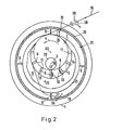
- the thread guide disk 21 ensures that the distance D between the disk 21 and the balloon breaker 26 - as is particularly evident from FIG. 2 - is essentially the same over the entire circumference.
- the thread balloon 27 therefore slides at 34 on the guide disk 21 and at. 35 on the inner circumference 37 of the balloon breaker 26.
- the centrifugal force which occurs in the balloon 27 changes at most only slightly during the thread withdrawal. This means that even sensitive yarns can be processed, e.g. Fiberglass material.
- the constant centrifugal force in the thread balloon 27 prevents the drawn weft thread in the region of the balloon 27 from striking the inner circumference 37 of the balloon breaker 26 with an uneven strength, as a result of which breaks in the individual fibrils of the weft thread 16 and thus tissue defects can be prevented.
- the winding body 25 consisting of the parts 2, 5 can stand still and the weft thread 16 is fed through a tubular winder (flyer) 39, indicated in dashed lines in FIG. 2 and rotating according to arrow 38.
- a ring can also be used as the thread guide member on the take-off side 17 of the winding body 25. whose shape may correspond approximately to the part of the disk 21 shown in FIG. 2.
Landscapes
- Engineering & Computer Science (AREA)
- Textile Engineering (AREA)
- Looms (AREA)
Abstract
Description
- Die Erfindung betrifft einen Schussfadenspeicher für eine Webmaschine, mit einem radial verstellbare Umfangselemente aufweisenden Wickelkörper und einem Ballonbrecher für den von dem Wickelkörper abzuziehenden, in das Webfach der Webmaschine einzutragenden Schussfaden.
- Bei einem bisherigen Schussfadenspeicher dieser Art (DE-OS 29 20 629 - US-PS 4 238 080 / TS 263) rotiert der Wickelkörper während des Betriebes mehr oder weniger exzentrisch zu der ortsfesten Schussfadenspeicher-Achse, je nachdem welche Radialposition die verstellbaren Umfangselemente einnehmen. Wird der Speicher etwa entsprechend DE-PS 20 28 543 - US-PS 3 761 031 / T. 366, Bezugszeichen 101 auf der Fadenabzugsseite in Verbindung mit einem Ballonbrecher benutzt -- was die Regel ist -- , so können in dem Fadenballon des abgezogenen Schussfadens ungleich starke Zentrifugalkräfte entstehen. Der Schussfaden wird dann ständig verschieden stark gegen den Ballonbrecher geschlagen. Je nach Schussgarn können diese unkonstanten Zentrifugalkräfte sich schädlich auf den Faden auswirken. Insbesondere können z.B. einzelne Fibrillen eines Glasfaser-Schussgarnes brechen, wodurch Gewebefehler entstehen können.
- Der Erfindung liegt die Aufgabe zugrunde, einen besonders in dieser Hinsicht verbesserten Schussfadenspeicher zu schaffen.
- Die Erfindung liegt in einem auf der Fadenabzugs-Stirnseite des Wickelkörpers angeordneten, ringförmigen, relativ zu dem Ballonbrecher konzentrisch angeordneten Fadenführungsglied zum Erzeugen konstanter Umfangsdistanz zwischen Wickelkörper und Ballonbrecher.
- Auf diese Weise lässt sich die in dem abgezogenen und zum Eintrag in der Webmaschine kommenden Schussfaden entstehende Zentrifugalkraft -- wie die Versuche ergeben haben -- im wesentlichen konstant halten. Der Schussfaden schlägt dann nicht mehr stossförmig gegen den Ballonbrecher, sondern läuft mit der konstanten Zentrifugalkraft tangierend entlang dem Innenumfang des Ballonbrechers. Auch empfindliche Schussgarne, wie z.B. Glasfasermaterialien, lassen sich dann ohne Schaden in das Webfach der Webmaschine eintragen. Das entstehende Gewebe enthält keine Gewebefehler, z.B. sichtbare, diskontinuierliche Stellen mehr, die auf Fibrillenbrüche des Schussfadens zurückzuführen wären.
- Weitere Merkmale ergeben sich aus der folgenden Beschreibung von Ausführungsbeispielen in Verbindung mit der Zeichnung und den Ansprüchen.
- Fig. 1 ist eine Seitenansicht eines erfindungsgemäss ausgebildeten Schussfadenspeichers, teilweise im Schnitt und schematisiert,
- Fig. 2 ist eine zugehörige Stirnansicht in Richtung A in Fig. 1 und
- i Fig. 3 zeigt ein Detail aus Fig. 1 in grösserem Massstab.
- In einem ortsfest angeordneten Gestell 1 ist eine eine Achse 60 aufweisende Wickeltrommel 2 um eine ortsfeste Achse 3 rotierend (Pfeil 4) angeordnet. Auf der in Fig. 1,2 unteren Seite der Wickeltrommel 2 sind mehrere, mit der Trommel 2 rotierende Fadenträger-Bügel 5 angebracht. Der Wickelkörper besteht somit aus der Wickeltrommel 2 und den TrägerbUgeln 5, die gemeinsam um die Achse 3 rotieren. Die einen Enden 6 der Trägerbügel 5 ragen in Schlitze 7 einer rotierenden Grundscheibe 8, die anderen Enden 9 der Bügel 5 treten in Bohrungen 11 der Wickeltrommel 2 ein und sind mittels Klemmschrauben 51 radial entsprechend den Pfeilen 12 einstellbar. Dadurch lässt sich auch die Trägerpartie 13 der Bügel 5, die im wesentlichen parallel zur Achse 3 verläuft, radial einstellen, so dass der Wickelumfang des aus den Teilen 2,5 bestehenden Wickelkörpers 25 verstellbar wird. Dadurch lässt sich auch die Länge einer Windung 14 des von Spule 15 kommenden Schussfaden 16 einstellen.
- Auf der Stirnfläche 17 der Wickeltrommel 2 ist eine Zwischenscheibe 18 und darauf mittels einer exzentrisch zu Achse 3 angeordneten Schraube 19 und eines Deckels 20 eine in Fig. 2 zur Mitte hin abgebrochen gezeichnete Fadenführungsscheibe 21 befestigt. Ihr hinterer Teil 22 ist um die Trägerscheibe 18 herum verlängert.
- Der Wickelkörper 25 ist von einem konzentrisch zur Achse 3 angeordneten Ballonbrecher 26 umschlossen, durch den der Ballon 27 des abgezogenen Schussfadens 16 begrenzt wird. Der Schussfaden gelangt während des Webbetriebes durch eine Oese 52 der schematisch angedeuteten Webmaschine 53 in das von den Kettfäden 54 gebildete Webfach 55.
- Auf dem Umfang 28 des Wickelkörpers 2 ist ein parallel zur Achse 3 verlaufender Schlitz 29 vorgesehen, durch welchen mit der Wickeltrommel 2 umlaufende Stifte 31 austreten können. Während ihres Umlaufes mit der Wickeltrommel 2 werden die Stifte 31 entsprechend Pfeil 32 bewegt, so dass sie bei Position 31a aus dem Umfang der Wickeltrommel 2 austreten und über Position 31b wieder eintreten und somit vom Umfang verschwinden. Dadurch kann das Fadenwindungspaket 33 in Fig. 1 nach rechts über Kopf abgezogen und in das Webfach 55 eingetragen werden. Während des Fadenabzuges werden links von Position 31a neue Windungen 14b auf den Wickelkörper 25 aufgewickelt.
- Durch die Fadenführungsscheibe 21 wird dafür gesorgt, dass die Distanz D zwischen Scheibe 21 und Ballonbrecher 26 -- wie sich besonders aus Fig. 2 ergibt -- auf dem ganzen Umfang im wesentlichen gleich gross ist. Der Fadenballon 27 gleitet daher bei 34 auf der Führungsscheibe 21 und bei. 35 auf dem Innenumfang 37 des Ballonbrechers 26. Die Zentrifugalkraft, die im Ballon 27 auftritt, ändert sich während des Fadenabzuges höchstens geringfügig. Dadurch können auch empfindliche Garne verarbeitet werden, z.B. Glasfasermaterial. Durch die konstante Zentrifugalkraft im Fadenballon 27 wird vermieden, dass der abgezogene Schussfaden im Bereich des Ballons 27 in ungleicher Stärke an den Innenumfang 37 des Ballonbrechers 26 schlagen kann, wodurch Brüche der einzelnen Fibrillen des Schussfadens 16 und damit Gewebefehler verhindert werden können.
- Bei einer anderen Bauart kann der aus den Teilen 2,5 bestehende Wickelkörper 25 stillstehen und der Schussfaden 16 wird durch einen in Fig. 2 gestrichelt angedeuteten, entsprechend Pfeil 38 rotierenden, rohrförmigen Wickler (Flyer) 39 zugeführt werden. Statt der durchgehenden Scheibe 21 kann als Fadenführungsglied auf der Abzugsseite 17 des Wickelkörpers 25 auch ein Ring verwendet werden, dessen Gestalt etwa dem in Fig. 2 dargestellten Teil der Scheibe 21 entsprechen kann.
Claims (3)
Priority Applications (4)
| Application Number | Priority Date | Filing Date | Title |
|---|---|---|---|
| EP83810545A EP0142591B1 (de) | 1983-11-22 | 1983-11-22 | Schussfadenspeicher für eine Webmaschine |
| DE8383810545T DE3372297D1 (en) | 1983-11-22 | 1983-11-22 | Weft yarn storage unit for looms |
| US06/672,142 US4633917A (en) | 1983-11-22 | 1984-11-16 | Weft thread storage device for a weaving machine |
| JP59244714A JPH06104943B2 (ja) | 1983-11-22 | 1984-11-21 | 織機用ヨコ糸貯蔵器 |
Applications Claiming Priority (1)
| Application Number | Priority Date | Filing Date | Title |
|---|---|---|---|
| EP83810545A EP0142591B1 (de) | 1983-11-22 | 1983-11-22 | Schussfadenspeicher für eine Webmaschine |
Publications (2)
| Publication Number | Publication Date |
|---|---|
| EP0142591A1 true EP0142591A1 (de) | 1985-05-29 |
| EP0142591B1 EP0142591B1 (de) | 1987-07-01 |
Family
ID=8191576
Family Applications (1)
| Application Number | Title | Priority Date | Filing Date |
|---|---|---|---|
| EP83810545A Expired EP0142591B1 (de) | 1983-11-22 | 1983-11-22 | Schussfadenspeicher für eine Webmaschine |
Country Status (4)
| Country | Link |
|---|---|
| US (1) | US4633917A (de) |
| EP (1) | EP0142591B1 (de) |
| JP (1) | JPH06104943B2 (de) |
| DE (1) | DE3372297D1 (de) |
Cited By (4)
| Publication number | Priority date | Publication date | Assignee | Title |
|---|---|---|---|---|
| EP0188636A1 (de) * | 1985-01-18 | 1986-07-30 | GebràDer Sulzer Aktiengesellschaft | Vorrichtung zum Speichern von fadenförmigem Material |
| US4850400A (en) * | 1987-04-24 | 1989-07-25 | Sulzer Brothers Limited | Weft yarn store with automatic yarn measurement |
| EP0363980A1 (de) * | 1988-10-14 | 1990-04-18 | ROJ ELECTROTEX S.p.A. | Schussfadenreserve-Aufwickelvorrichtung mit variabler Länge der Fadenreservewindungen zum Gebrauch in Schussfadenmess- und -liefervorrichtungen für Webmaschinen |
| WO1995030033A1 (en) * | 1994-05-03 | 1995-11-09 | Te Strake B.V. | Pre unwinding device for use in a shuttleless weaving loom and weaving loom provided with such a device |
Families Citing this family (5)
| Publication number | Priority date | Publication date | Assignee | Title |
|---|---|---|---|---|
| DE3601586C1 (de) * | 1986-01-21 | 1987-05-27 | Memminger Gmbh | Fadenspeicher- und -liefervorrichtung,insbesondere fuer Textilmaschinen |
| IT1247886B (it) * | 1991-05-03 | 1995-01-05 | Candia Ets | Fornitore di trama per telai senza navetta |
| JP2500524Y2 (ja) * | 1991-05-10 | 1996-06-05 | 株式会社オーゼン | 小型モ―タの軸受装置 |
| US6915831B2 (en) * | 2000-07-21 | 2005-07-12 | Hunter Douglas Inc. | Drum for wrapping a cord |
| ITTO20010569A1 (it) * | 2001-06-14 | 2002-12-14 | Lgl Electronics Spa | Dispositivo di regolarizzazione dello svolgimento delle spire di filodella riserva di trama, dal tamburo degli alimentatori di trama per te |
Citations (2)
| Publication number | Priority date | Publication date | Assignee | Title |
|---|---|---|---|---|
| DE2028543A1 (de) * | 1970-05-14 | 1971-11-25 | Gebrüder Sulzer AG, Winterthur (Schweiz) | Speichereinrichtung für fadenartiges Material |
| DE2920629A1 (de) * | 1978-06-15 | 1980-01-03 | Rueti Te Strake Bv | Vorrichtung zum bilden eines vorratswickels aus einem von einem garnvorrat angefuehrten faden |
Family Cites Families (4)
| Publication number | Priority date | Publication date | Assignee | Title |
|---|---|---|---|---|
| CH569655A5 (de) * | 1973-09-25 | 1975-11-28 | Sulzer Ag | |
| DE2743749C3 (de) * | 1977-09-29 | 1984-10-11 | SIPRA Patententwicklungs-und Beteiligungsgesellschaft mbH, 7000 Stuttgart | Fadenspeicher- und -liefervorrichtung für Textilmaschinen |
| DE2839437C2 (de) * | 1978-09-11 | 1980-04-24 | Ab Iro, Ulricehamn (Schweden) | Fadenspeicher- und -liefervorrichtung |
| CS272202B2 (en) * | 1981-10-13 | 1991-01-15 | Saurer Diederichs Sa | Doser and weft meter for shuttless looms |
-
1983
- 1983-11-22 DE DE8383810545T patent/DE3372297D1/de not_active Expired
- 1983-11-22 EP EP83810545A patent/EP0142591B1/de not_active Expired
-
1984
- 1984-11-16 US US06/672,142 patent/US4633917A/en not_active Expired - Fee Related
- 1984-11-21 JP JP59244714A patent/JPH06104943B2/ja not_active Expired - Lifetime
Patent Citations (2)
| Publication number | Priority date | Publication date | Assignee | Title |
|---|---|---|---|---|
| DE2028543A1 (de) * | 1970-05-14 | 1971-11-25 | Gebrüder Sulzer AG, Winterthur (Schweiz) | Speichereinrichtung für fadenartiges Material |
| DE2920629A1 (de) * | 1978-06-15 | 1980-01-03 | Rueti Te Strake Bv | Vorrichtung zum bilden eines vorratswickels aus einem von einem garnvorrat angefuehrten faden |
Cited By (8)
| Publication number | Priority date | Publication date | Assignee | Title |
|---|---|---|---|---|
| EP0188636A1 (de) * | 1985-01-18 | 1986-07-30 | GebràDer Sulzer Aktiengesellschaft | Vorrichtung zum Speichern von fadenförmigem Material |
| US4643369A (en) * | 1985-01-18 | 1987-02-17 | Sulzer Brothers Limited | Storage device for filamentary material |
| US4850400A (en) * | 1987-04-24 | 1989-07-25 | Sulzer Brothers Limited | Weft yarn store with automatic yarn measurement |
| EP0363980A1 (de) * | 1988-10-14 | 1990-04-18 | ROJ ELECTROTEX S.p.A. | Schussfadenreserve-Aufwickelvorrichtung mit variabler Länge der Fadenreservewindungen zum Gebrauch in Schussfadenmess- und -liefervorrichtungen für Webmaschinen |
| US5046537A (en) * | 1988-10-14 | 1991-09-10 | Roj Electrotex S.P.A. | Weft yarn reserve winding unit with adjustable diameter winding drum |
| WO1995030033A1 (en) * | 1994-05-03 | 1995-11-09 | Te Strake B.V. | Pre unwinding device for use in a shuttleless weaving loom and weaving loom provided with such a device |
| NL9400726A (nl) * | 1994-05-03 | 1995-12-01 | Te Strake Bv | Voorafwikkelinrichting voor toepassing bij een spoelloos weefgetouw en weefgetouw voorzien van een dergelijke inrichting. |
| US5725027A (en) * | 1994-05-03 | 1998-03-10 | Te Strake B.V. | Weft feeder |
Also Published As
| Publication number | Publication date |
|---|---|
| US4633917A (en) | 1987-01-06 |
| JPS60185845A (ja) | 1985-09-21 |
| EP0142591B1 (de) | 1987-07-01 |
| JPH06104943B2 (ja) | 1994-12-21 |
| DE3372297D1 (en) | 1987-08-06 |
Similar Documents
| Publication | Publication Date | Title |
|---|---|---|
| DE2225918C3 (de) | Verfahren für den Abzug fadenförmigen Materials von einem Wickelkörper einer Speichereinrichtung für Textilmaschinen und Einrichtung zur Durchführung des Verfahrens | |
| DE1535639C2 (de) | Schußfaden-Zwischenspeicher für Webmaschinen mit feststehender Schußfaden-Vorratsspule | |
| AT401065B (de) | Einrichtung zur überwachung der schussfäden an einer rundwebmaschine | |
| EP0142591B1 (de) | Schussfadenspeicher für eine Webmaschine | |
| EP0220546A1 (de) | Spinnvorrichtung zum Offenend-Spinnen | |
| DE2913762A1 (de) | Umwindespinnmaschine | |
| DE3501944C2 (de) | ||
| DE4336994C1 (de) | Fadenliefervorrichtung mit stufenlos einstellbarer Fadenabzugspannung | |
| DE2550701A1 (de) | Vorrichtung zum ablagern von fadenvorrat, insbesondere schussfadenvorrat fuer nichtorthodoxe webstuehle | |
| EP0719354B1 (de) | Projektil- oder greiferschützen-webmaschine und liefergerät | |
| DE3236942A1 (de) | Aufspulvorrichtung fuer synthetische faeden | |
| DE2535368A1 (de) | Doppeldrahtzwirnspindel | |
| DE1160340B (de) | Doppeldrahtzwirnspindel mit Fadenspeicherrinne und im Fadenlauf vor dieser liegenden Fadenbremse | |
| DE3619097A1 (de) | Fadenliefervorrichtung | |
| EP0517655B1 (de) | Verfahren und Vorrichtung zum Schären von Fäden auf die Schärtrommel einer Konus-Schärmaschine | |
| DE2655338C3 (de) | Offenendspinnvorrichtung | |
| EP1083252A2 (de) | Vorspulgerät für Luftdüsenwebmaschinen | |
| EP0188636A1 (de) | Vorrichtung zum Speichern von fadenförmigem Material | |
| DE6950418U (de) | Doppeldrahtzwirnspindel. | |
| DE7519436U (de) | Einrichtung zum Speichern von fadenförmigem Material | |
| DE69317019T2 (de) | Vorrichtung zum Speisen eines periodisch arbeitenden Fadenverbrauchers | |
| AT277098B (de) | Spulengestell für Webmaschinen | |
| DE612109C (de) | Verfahren zum Ausgleichen von Fadenspannungsschwankungen auf Ringspinn- und Ringzwirnmaschinen | |
| EP0217373A2 (de) | Fadenliefervorrichtung für Textilmaschinen | |
| AT224031B (de) | Webmaschine |
Legal Events
| Date | Code | Title | Description |
|---|---|---|---|
| PUAI | Public reference made under article 153(3) epc to a published international application that has entered the european phase |
Free format text: ORIGINAL CODE: 0009012 |
|
| 17P | Request for examination filed |
Effective date: 19831124 |
|
| AK | Designated contracting states |
Designated state(s): AT BE CH DE FR GB IT LI LU NL SE |
|
| RBV | Designated contracting states (corrected) |
Designated state(s): BE CH DE FR GB IT LI |
|
| 17Q | First examination report despatched |
Effective date: 19860509 |
|
| ITF | It: translation for a ep patent filed | ||
| GRAA | (expected) grant |
Free format text: ORIGINAL CODE: 0009210 |
|
| AK | Designated contracting states |
Kind code of ref document: B1 Designated state(s): BE CH DE FR GB IT LI |
|
| REF | Corresponds to: |
Ref document number: 3372297 Country of ref document: DE Date of ref document: 19870806 |
|
| ET | Fr: translation filed | ||
| PLBE | No opposition filed within time limit |
Free format text: ORIGINAL CODE: 0009261 |
|
| STAA | Information on the status of an ep patent application or granted ep patent |
Free format text: STATUS: NO OPPOSITION FILED WITHIN TIME LIMIT |
|
| 26N | No opposition filed | ||
| PG25 | Lapsed in a contracting state [announced via postgrant information from national office to epo] |
Ref country code: GB Effective date: 19881122 |
|
| PG25 | Lapsed in a contracting state [announced via postgrant information from national office to epo] |
Ref country code: LI Effective date: 19881130 Ref country code: CH Effective date: 19881130 |
|
| GBPC | Gb: european patent ceased through non-payment of renewal fee | ||
| REG | Reference to a national code |
Ref country code: CH Ref legal event code: PL |
|
| PGFP | Annual fee paid to national office [announced via postgrant information from national office to epo] |
Ref country code: BE Payment date: 19901217 Year of fee payment: 8 |
|
| ITTA | It: last paid annual fee | ||
| PG25 | Lapsed in a contracting state [announced via postgrant information from national office to epo] |
Ref country code: BE Effective date: 19911130 |
|
| BERE | Be: lapsed |
Owner name: MASCHINENFABRIK SULZER-RUTI A.G. Effective date: 19911130 |
|
| PGFP | Annual fee paid to national office [announced via postgrant information from national office to epo] |
Ref country code: FR Payment date: 19921109 Year of fee payment: 10 |
|
| PGFP | Annual fee paid to national office [announced via postgrant information from national office to epo] |
Ref country code: DE Payment date: 19921212 Year of fee payment: 10 |
|
| PG25 | Lapsed in a contracting state [announced via postgrant information from national office to epo] |
Ref country code: FR Effective date: 19940729 |
|
| PG25 | Lapsed in a contracting state [announced via postgrant information from national office to epo] |
Ref country code: DE Effective date: 19940802 |
|
| REG | Reference to a national code |
Ref country code: FR Ref legal event code: ST |