EP0142593A1 - Commutateur d'un clavier avec un levier d'action pivotant - Google Patents
Commutateur d'un clavier avec un levier d'action pivotant Download PDFInfo
- Publication number
- EP0142593A1 EP0142593A1 EP84100040A EP84100040A EP0142593A1 EP 0142593 A1 EP0142593 A1 EP 0142593A1 EP 84100040 A EP84100040 A EP 84100040A EP 84100040 A EP84100040 A EP 84100040A EP 0142593 A1 EP0142593 A1 EP 0142593A1
- Authority
- EP
- European Patent Office
- Prior art keywords
- plunger
- lever
- switch
- housing
- movement
- Prior art date
- Legal status (The legal status is an assumption and is not a legal conclusion. Google has not performed a legal analysis and makes no representation as to the accuracy of the status listed.)
- Granted
Links
Images


Classifications
-
- H—ELECTRICITY
- H01—ELECTRIC ELEMENTS
- H01H—ELECTRIC SWITCHES; RELAYS; SELECTORS; EMERGENCY PROTECTIVE DEVICES
- H01H13/00—Switches having rectilinearly-movable operating part or parts adapted for pushing or pulling in one direction only, e.g. push-button switch
- H01H13/70—Switches having rectilinearly-movable operating part or parts adapted for pushing or pulling in one direction only, e.g. push-button switch having a plurality of operating members associated with different sets of contacts, e.g. keyboard
- H01H13/702—Switches having rectilinearly-movable operating part or parts adapted for pushing or pulling in one direction only, e.g. push-button switch having a plurality of operating members associated with different sets of contacts, e.g. keyboard with contacts carried by or formed from layers in a multilayer structure, e.g. membrane switches
- H01H13/705—Switches having rectilinearly-movable operating part or parts adapted for pushing or pulling in one direction only, e.g. push-button switch having a plurality of operating members associated with different sets of contacts, e.g. keyboard with contacts carried by or formed from layers in a multilayer structure, e.g. membrane switches characterised by construction, mounting or arrangement of operating parts, e.g. push-buttons or keys
-
- H—ELECTRICITY
- H01—ELECTRIC ELEMENTS
- H01H—ELECTRIC SWITCHES; RELAYS; SELECTORS; EMERGENCY PROTECTIVE DEVICES
- H01H13/00—Switches having rectilinearly-movable operating part or parts adapted for pushing or pulling in one direction only, e.g. push-button switch
- H01H13/02—Details
- H01H13/12—Movable parts; Contacts mounted thereon
- H01H13/20—Driving mechanisms
-
- H—ELECTRICITY
- H01—ELECTRIC ELEMENTS
- H01H—ELECTRIC SWITCHES; RELAYS; SELECTORS; EMERGENCY PROTECTIVE DEVICES
- H01H2215/00—Tactile feedback
- H01H2215/034—Separate snap action
Definitions
- the present invention relates to a keyboard switch of the type conventionally used in connection with an underlying membrane switch array.
- a specific purpose of the invention is to provide such a keyboard switch which has a lever pivotally mounted on the key housing and cammed away from a switch closure position until such time as the plunger or key has moved inwardly a given distance.
- a primary purpose of the invention is a keyboard switch of the type described in which the lever causing a switch closure is held away from a switch closing position until the operating plunger or key has moved inwardly a given distance, after which the switch closing lever will suddenly move to a switch closure position. This provides a tactile feel to indicate when a switch closure has in fact taken place.
- keyboard switch of the type described including sloped cam surfaces which allow the actuator lever to gradually apply a switch closing force during inward movement of the plunger.
- Another purpose is a keyboard switch of the type described in which the return spring also provides the force required for switch closure movement.
- Another purpose is a simply constructed, reliably operable switch of the type described.
- the present invention relates to a keyboard switch in which the point of closure or "make point" is dependent on the geometry of the switch parts and not on the force applied to the switch.
- the switch will close only after the plunger has moved inwardly a given distance. Only upon such movement will the switch parts assume positions wherein the geometry of the parts allows application of a closing force to the membrane switch.
- the application of the closing force may be gradual or sudden.
- the force applied to the membrane switch is a smooth, continuous function of the plunger travel; there are no sudden changes in the force. Since the force-deflection curve is generally a straight line, this switch is called a linear switch.
- the tactile switch of the present invention finds utility in keyboards, such as computer terminals, typewriters, calculators and other applications in which it is desirable that the key have a very low profile.
- the total height of the entire key structure disclosed herein normally will not be greater than one-half inch.
- the travel of the key actuator from the unoperated to the operated position will normally be quite small. In the present instance such travel may be on the order of slightly more than one-eighth inch.
- the present invention is specifically directed to such a tactile key and to a means for providing a tactile feel in key operation.
- the tactile feel must not be a gradual sensation, but, rather,,there must be an abrupt or sudden movement in operation of the key so that the operator is assured and in fact completely confident that switch operation has taken place.
- the tactile switch includes a housing indicated generally at 10 having a central opening 12 mounting a reciprocal plunger 14.
- the plunger may mount a keycap 16 of a conventional size and shape for keyboard operation.
- Pivotally mounted on the housing and in position to be in cooperative contact with plunger 14 is a lever 18 which will be described in more detail hereinafter.
- Housing 12 is seated upon a membrane switch array which may consist of the conventional lower substrate 20, intermediate spacer 22 and membrane 24.
- the membrane and substrate will have electrical contacts thereon which normally will be positioned beneath plunger 14.
- There will be the usual opening 26 in the spacer beneath the switch so that movement of keycap 16 and thus plunger 14 can effect a switch closure between the membrane and substrate.
- Housing 10 has a cylindrical wall 28 which defines opening 12 and that portion of housing 10 beneath opening 12 may have arcuate slots 30 just inside of wall 28, with slots 30 cooperating with arcuate projections 32 on the bottom of the plunger to maintain alignment and relative position between these two elements during switch operation.
- the bottom of the housing may have an opening 31 which will permit lever 18 to effect a switch closure.
- housing 10 has oppositely-disposed hook elements 34, illustrated in Figure 6, which will ride in cooperating grooves 36 on the sides of the plunger. Note that grooves 36 have a lower surface 38 forming a stop which prevents removal of the plunger from the housing opening. When the plunger is initially inserted during assembly, the plunger will be pushed past hooks 34 which will flex to permit assembly. Once assembled, the plunger cannot be removed from the housing.
- Lever 18 has a pivot portion 40 which is positioned within a slot 42 of housing portion 44 formed at one corner of the housing. Lever 18 is accordingly mounted for pivotal movement between the Figure 2 and 3 positions.
- Lever 18 has a spring support portion 46 which extends through an opening in wall 28 of the housing and provides a spring seat 48 which will seat a coil spring 50 which is captured between the spring seat and an inner surface 52 of plunger 14.
- spring seat portion 46 of lever 18 includes a downward projecting boss 54 which is positioned, as specifically illustrated in Figure 3, to provide a closure of the underlying membrane switch by forcing a portion of membrane 24 through opening 26 in the spacer so that there is contact between the electrical conductive areas of the membrane and substrate.
- lever 18 has a reset ramp 56 and a threshold ramp 58 with the reset ramp and threshold being separated by an open area or slot 60.
- lever 18 has a nose 62 which is positioned in alignment with reset ramp 56 and an arm 64 which cooperates with threshold 58 to hold the lever in the non-actuated position of Figures 2 and 4 until such time as arm 64 is in alignment with threshold 58.
- Lever 18 further has a stop 66 positioned directly behind arm 64 which restricts movement of the arm to a single plane.
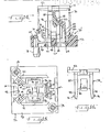
- FIGS 14-16 illustrate an alternate embodiment of the invention.
- This is the linear switch referred to above.
- Linear switch 70 has three main parts; a housing 72, a plunger 74 and a spring 76. It will be understood that the switch is designed for use with a membrane switch array mounted on a base plate, although the membrane switch array and base plate are not shown. The switch is attached to the base plate by a pair of expandable rivets 78.
- the plunger 74 includes a body portion 80 to which a cap 82 is connected.
- the cap engages the spring 76 as shown in Figure 14.
- An appropriate key top (not shown) would be attached to the cap 82.
- a pair of integrally formed legs 84 extend from either side of the body 80.
- the legs 84 carry hooks 86 near their ends.
- a cam surface 88 is formed on one side of the body 80. As shown in Figure 14, the cam surface has a gradual, sloped configuration.
- the housing 72 includes a generally flat base 90 having a central opening 92 therein.
- a pair of upstanding walls are located in facing relation on either side of the opening 92.
- Each wall includes an elongated lower portion 94 and a U-shaped upper portion 96 which extends above the lower portion 94.
- the bight of the U-shaped wall includes a groove or channel 98 in which the hooks 86 of the plunger ride.
- the groove 98 extends about halfway up the wall portion 96. Its terminus forms an up stop for the plunger.
- the lower portions 94 of the walls provide a base on which the spring 76 bottoms.
- the housing includes a chamber 100 in which an optional cam follower may be inserted to provide an alternate action-type switch.
- the housing also has an upstanding spring support wall 102. Along with the wall portions 94, the spring support 102 provides a base on which the spring 76 rests.
- the actuator lever 104 is shown generally at 104.
- the lever is disposed above the housing opening 92 and between the walls 94,96.
- the actuator lever 104 includes an elongated, upright bracket 106.
- the bracket is pivotally attached to the base of the housing by a flexible hinge 108, commonly referred to as a living hinge.
- a pair of extension pieces 110 are connected to the top of the bracket and extend downwardly therefrom.
- the extensions merge into a pair of legs 112 which extend generally horizontally across the bottom of the housing.
- the legs 112 extend beyond the wall portions 96 and terminate with a pair of upturned feet 114.
- Each foot 114 has two tabs 116 which form a slot between them for retaining the spring 76, as best seen in Figure 14.
- the legs 112 are connected by a strap 118. On the underside of the strap there is a knob 120 which is the part that actually contacts the membrane switch.
- a cam surface 122 is formed at the upper end of the bracket 106. This surface is in the nature of a cam follower as it engages the cam surface 88 on the plunger 74.
- the operation of the linear switch is as follows.
- the plunger body 80 and legs 84 are disposed in the housing between the U-shaped walls 96.
- the hooks 86 slide in the grooves 98 and are retained therein.
- the spring 76 is compressed between the plunger cap 82 and the lower wall portions 94, the spring support 102 and the feet 114 of the actuator lever 104.
- the spring urges the lever toward the membrane switch, i.e., in a counterclockwise direction (as seen in Figure 14) about the hinge 108.
- the switch is in the unoperated, rest position (as in Figure 14) the lever is restrained from moving into a membrane switch closing position by the engagement of the cam follower 122 on the cam surface 88.
- the cam surface 88 When a user pushes the plunger inwardly, the cam surface 88 allows the lever 104 to pivot about the hinge 108 and bring the knob 120 into contact with the membrane switch.
- the compressed spring acts on the lever to gradually apply a membrane switch closing force through the knob 120.
- the cam surface 88 has a sloped configuration. This permits the gradual application of switch closing force in a smooth and continuous manner.
- the spring 76 causes the plunger to move outwardly in the housing while at the same time the cam surface 88 resets the actuator lever 104 to its rest or non-operative position. It can be seen that the cam surface 88 prevents the lever from moving to a switch closing position until the plunger has moved inwardly a given distance. That distance can be regulated by the shape of the cam surface.
- cam surface 88 does not have to have a smooth and continuous configuration. It could also have a sharp step or drop-off which would prevent any movement of the lever until the last possible moment. Then the lever would be released suddenly with the switch closing force being applied effectively instantaneously. This would provide a tactile feel as in the switch of Figures 1-13.
Landscapes
- Push-Button Switches (AREA)
- Switches With Compound Operations (AREA)
Priority Applications (1)
| Application Number | Priority Date | Filing Date | Title |
|---|---|---|---|
| AT84100040T ATE30982T1 (de) | 1983-11-21 | 1984-01-03 | Tastaturschalter mit drehbar gelagertem betaetigungshebel. |
Applications Claiming Priority (2)
| Application Number | Priority Date | Filing Date | Title |
|---|---|---|---|
| US06/553,966 US4553009A (en) | 1982-09-03 | 1983-11-21 | Keyboard switch with pivotal actuator lever |
| US553966 | 1983-11-21 |
Publications (2)
| Publication Number | Publication Date |
|---|---|
| EP0142593A1 true EP0142593A1 (fr) | 1985-05-29 |
| EP0142593B1 EP0142593B1 (fr) | 1987-11-19 |
Family
ID=24211508
Family Applications (1)
| Application Number | Title | Priority Date | Filing Date |
|---|---|---|---|
| EP84100040A Expired EP0142593B1 (fr) | 1983-11-21 | 1984-01-03 | Commutateur d'un clavier avec un levier d'action pivotant |
Country Status (5)
| Country | Link |
|---|---|
| US (1) | US4553009A (fr) |
| EP (1) | EP0142593B1 (fr) |
| JP (1) | JPS60131721A (fr) |
| AT (1) | ATE30982T1 (fr) |
| DE (1) | DE3467658D1 (fr) |
Cited By (7)
| Publication number | Priority date | Publication date | Assignee | Title |
|---|---|---|---|---|
| EP0353900A1 (fr) * | 1988-08-02 | 1990-02-07 | Acer Peripherals, Inc. | Interrupteur pour clavier |
| EP0464339A3 (en) * | 1990-07-05 | 1992-08-19 | Grundig E.M.V. Elektro-Mechanische Versuchsanstalt Max Grundig Hollaend. Stiftung & Co. Kg. | Push button switch installation for an electronic apparatus |
| EP0543649A3 (en) * | 1991-11-19 | 1993-07-07 | Brother Kogyo Kabushiki Kaisha | Keyswitch assembly |
| US5278371A (en) * | 1992-02-14 | 1994-01-11 | Brother Kogyo Kabushiki Kaisha | Keyswitch assembly with support mechanism coupled to support plate beneath printed circuit board |
| US5278372A (en) * | 1991-11-19 | 1994-01-11 | Brother Kogyo Kabushiki Kaisha | Keyboard having connecting parts with downward open recesses |
| US5278374A (en) * | 1992-02-14 | 1994-01-11 | Brother Kogyo Kabushiki Kaisha | Assembly with an asymmetrical resilient spring |
| EP0749136A3 (fr) * | 1995-06-14 | 1998-04-29 | Elektro-Apparatebau Olten AG | Commutateur pour ouvrir une porte |
Families Citing this family (17)
| Publication number | Priority date | Publication date | Assignee | Title |
|---|---|---|---|---|
| DE3530050A1 (de) * | 1985-08-22 | 1987-02-26 | Cherry Mikroschalter Gmbh | Tastenmodul fuer folientastaturen |
| US4761522A (en) * | 1986-10-06 | 1988-08-02 | Allen Donald E | Finger operated switching apparatus |
| US4769516A (en) * | 1986-10-06 | 1988-09-06 | Allen Donald E | Finger operated switching apparatus |
| JPH01150337U (fr) * | 1988-04-11 | 1989-10-18 | ||
| US4899244A (en) * | 1988-07-28 | 1990-02-06 | Polaroid Corporation | Disk cartridge with hub seal |
| US4939327A (en) * | 1988-10-31 | 1990-07-03 | Acer Incorporated | Keyboard switch |
| US4931606A (en) * | 1989-04-28 | 1990-06-05 | International Business Machines Corporation | Key switch mechanism and membrane actuator |
| GB2238912A (en) * | 1989-07-28 | 1991-06-12 | Acer Inc | Pushbutton switch assembly |
| US5668358A (en) * | 1994-07-05 | 1997-09-16 | Ultimate Rechnology Corporation | Reconfigurable keyboard |
| DE69631535T2 (de) * | 1995-08-23 | 2005-01-05 | Matsushita Electric Industrial Co., Ltd., Kadoma | Elektronisches steuerelement |
| USD454120S1 (en) | 2000-11-10 | 2002-03-05 | Carling Technologies, Inc. | Electrical switch actuator |
| JP2018005700A (ja) * | 2016-07-05 | 2018-01-11 | 富士通コンポーネント株式会社 | キーボード |
| US10937610B2 (en) | 2018-06-22 | 2021-03-02 | Darfon Electronics Corp. | Keyboard keyswitches having adjustable tactile feedback members |
| US10930451B2 (en) * | 2018-06-22 | 2021-02-23 | Darfon Electronics Corp. | Keyswitch with adjustable tactile feedback |
| US11557444B2 (en) * | 2020-06-04 | 2023-01-17 | Hewlett-Packard Development Company, L.P. | Keyboard key switches |
| US11373822B2 (en) * | 2020-06-04 | 2022-06-28 | Hewlett-Packard Development Company, L.P. | Keyboard key switches |
| CN116798795A (zh) * | 2022-03-17 | 2023-09-22 | 致伸科技股份有限公司 | 键盘装置及其按键结构 |
Citations (6)
| Publication number | Priority date | Publication date | Assignee | Title |
|---|---|---|---|---|
| US3757068A (en) * | 1971-04-15 | 1973-09-04 | Hewlett Packard Co | Sms keyboard actuating mechanism with particular feel and contact mechani |
| DE2346392A1 (de) * | 1972-09-15 | 1974-03-28 | Victor Comptometer Corp | Tastatur, insbesondere fuer elektronische rechengeraete |
| US3969600A (en) * | 1975-06-11 | 1976-07-13 | Burroughs Corporation | Tactile feedback keyboard switch assembly and actuator |
| DE3111407A1 (de) * | 1981-03-24 | 1982-10-21 | Marquardt Gmbh, 7201 Rietheim-Weilheim | Tastenschalter |
| US4367380A (en) * | 1980-08-27 | 1983-01-04 | Oak Industries Inc. | Keyboard assembly and components therefor |
| EP0118131A2 (fr) * | 1983-03-07 | 1984-09-12 | Oak Industries Inc. | Touche à sensation tactile et à commande positive |
Family Cites Families (8)
| Publication number | Priority date | Publication date | Assignee | Title |
|---|---|---|---|---|
| US3656181A (en) * | 1970-10-20 | 1972-04-11 | Teletype Corp | Magnetically operable momentary switch assembly |
| US4314112A (en) * | 1971-08-23 | 1982-02-02 | Hewlett-Packard Company | Keyboard having switches with tactile feedback |
| US3856998A (en) * | 1973-06-01 | 1974-12-24 | Burroughs Corp | Keyboard switch assembly with improved operating means |
| US3982081A (en) * | 1974-09-04 | 1976-09-21 | Amp Incorporated | Keyboard assembly with overlapped flexible printed circuit cable switch |
| JPS6025782Y2 (ja) * | 1978-05-25 | 1985-08-02 | アルプス電気株式会社 | 押釦スイツチ |
| DE2838934C2 (de) * | 1978-09-07 | 1986-07-31 | J. & J. Marquardt, 7201 Rietheim-Weilheim | Elektrischer Schalter |
| US4447681A (en) * | 1983-02-22 | 1984-05-08 | Amp Incorporated | Switch key assembly having improved switch actuation |
| US4450331A (en) * | 1983-06-08 | 1984-05-22 | Amp Incorporated | Key switch assembly having momentary closed interval |
-
1983
- 1983-11-21 US US06/553,966 patent/US4553009A/en not_active Expired - Fee Related
-
1984
- 1984-01-03 DE DE8484100040T patent/DE3467658D1/de not_active Expired
- 1984-01-03 EP EP84100040A patent/EP0142593B1/fr not_active Expired
- 1984-01-03 AT AT84100040T patent/ATE30982T1/de not_active IP Right Cessation
- 1984-01-20 JP JP59008369A patent/JPS60131721A/ja active Granted
Patent Citations (6)
| Publication number | Priority date | Publication date | Assignee | Title |
|---|---|---|---|---|
| US3757068A (en) * | 1971-04-15 | 1973-09-04 | Hewlett Packard Co | Sms keyboard actuating mechanism with particular feel and contact mechani |
| DE2346392A1 (de) * | 1972-09-15 | 1974-03-28 | Victor Comptometer Corp | Tastatur, insbesondere fuer elektronische rechengeraete |
| US3969600A (en) * | 1975-06-11 | 1976-07-13 | Burroughs Corporation | Tactile feedback keyboard switch assembly and actuator |
| US4367380A (en) * | 1980-08-27 | 1983-01-04 | Oak Industries Inc. | Keyboard assembly and components therefor |
| DE3111407A1 (de) * | 1981-03-24 | 1982-10-21 | Marquardt Gmbh, 7201 Rietheim-Weilheim | Tastenschalter |
| EP0118131A2 (fr) * | 1983-03-07 | 1984-09-12 | Oak Industries Inc. | Touche à sensation tactile et à commande positive |
Cited By (8)
| Publication number | Priority date | Publication date | Assignee | Title |
|---|---|---|---|---|
| EP0353900A1 (fr) * | 1988-08-02 | 1990-02-07 | Acer Peripherals, Inc. | Interrupteur pour clavier |
| EP0464339A3 (en) * | 1990-07-05 | 1992-08-19 | Grundig E.M.V. Elektro-Mechanische Versuchsanstalt Max Grundig Hollaend. Stiftung & Co. Kg. | Push button switch installation for an electronic apparatus |
| EP0543649A3 (en) * | 1991-11-19 | 1993-07-07 | Brother Kogyo Kabushiki Kaisha | Keyswitch assembly |
| US5278372A (en) * | 1991-11-19 | 1994-01-11 | Brother Kogyo Kabushiki Kaisha | Keyboard having connecting parts with downward open recesses |
| US5280147A (en) * | 1991-11-19 | 1994-01-18 | Brother Kogyo Kabushiki Kaisha | Keyswitch assembly with a key support limiting transverse, longitudinal and rotational movement of the key |
| US5278371A (en) * | 1992-02-14 | 1994-01-11 | Brother Kogyo Kabushiki Kaisha | Keyswitch assembly with support mechanism coupled to support plate beneath printed circuit board |
| US5278374A (en) * | 1992-02-14 | 1994-01-11 | Brother Kogyo Kabushiki Kaisha | Assembly with an asymmetrical resilient spring |
| EP0749136A3 (fr) * | 1995-06-14 | 1998-04-29 | Elektro-Apparatebau Olten AG | Commutateur pour ouvrir une porte |
Also Published As
| Publication number | Publication date |
|---|---|
| US4553009A (en) | 1985-11-12 |
| ATE30982T1 (de) | 1987-12-15 |
| JPH0345497B2 (fr) | 1991-07-11 |
| EP0142593B1 (fr) | 1987-11-19 |
| DE3467658D1 (en) | 1987-12-23 |
| JPS60131721A (ja) | 1985-07-13 |
Similar Documents
| Publication | Publication Date | Title |
|---|---|---|
| US4553009A (en) | Keyboard switch with pivotal actuator lever | |
| US4467160A (en) | Low profile switch | |
| US5017747A (en) | Microswitch | |
| EP0543649A2 (fr) | Dispositif d'un commutateur à touche | |
| US5803243A (en) | Latching rocker switch | |
| US6087604A (en) | Thin keyboard | |
| US5012055A (en) | Spring loaded push-button switch having predictable switching time despite varying spring characteristics | |
| US4316066A (en) | Key switch with snap-action contact and resilient actuator | |
| CA1160269A (fr) | Interrupteur a bouton-poussoir et clef | |
| US4613737A (en) | Low profile pushbutton switch with tactile feedback | |
| US20020079204A1 (en) | Foot operated switch for electrical circuits | |
| US4904832A (en) | Microswitch | |
| CA1312896C (fr) | Bouton-poussoir, notamment pour commutateur verrouillable | |
| US6541716B2 (en) | Multidirectional switch device in which differences in tactile feel are reduced | |
| JPH0526652Y2 (fr) | ||
| CA1213927A (fr) | Commutateur de clavier a levier d'actionnement articule | |
| GB2058458A (en) | Key switch | |
| US6504122B2 (en) | Control device for a push-button type switch | |
| US4361743A (en) | Lost motion keyswitch | |
| US4571467A (en) | Three position center-off electrical switch | |
| EP0138136A2 (fr) | Adaptateur d'actionnement latéral pour un interrupteur à curseur | |
| JPH07107817B2 (ja) | マイクロスイッチ | |
| EP0314925A2 (fr) | Microrupteur | |
| EP0353900B1 (fr) | Interrupteur pour clavier | |
| JPS5926986Y2 (ja) | 押釦スイツチ |
Legal Events
| Date | Code | Title | Description |
|---|---|---|---|
| PUAI | Public reference made under article 153(3) epc to a published international application that has entered the european phase |
Free format text: ORIGINAL CODE: 0009012 |
|
| AK | Designated contracting states |
Designated state(s): AT BE CH DE FR GB IT LI NL SE |
|
| 17P | Request for examination filed |
Effective date: 19850403 |
|
| 17Q | First examination report despatched |
Effective date: 19860528 |
|
| GRAA | (expected) grant |
Free format text: ORIGINAL CODE: 0009210 |
|
| AK | Designated contracting states |
Kind code of ref document: B1 Designated state(s): AT BE CH DE FR GB IT LI NL SE |
|
| REF | Corresponds to: |
Ref document number: 30982 Country of ref document: AT Date of ref document: 19871215 Kind code of ref document: T |
|
| ITF | It: translation for a ep patent filed | ||
| REF | Corresponds to: |
Ref document number: 3467658 Country of ref document: DE Date of ref document: 19871223 |
|
| ET | Fr: translation filed | ||
| PLBE | No opposition filed within time limit |
Free format text: ORIGINAL CODE: 0009261 |
|
| STAA | Information on the status of an ep patent application or granted ep patent |
Free format text: STATUS: NO OPPOSITION FILED WITHIN TIME LIMIT |
|
| 26N | No opposition filed | ||
| ITTA | It: last paid annual fee | ||
| PGFP | Annual fee paid to national office [announced via postgrant information from national office to epo] |
Ref country code: NL Payment date: 19910131 Year of fee payment: 8 |
|
| PGFP | Annual fee paid to national office [announced via postgrant information from national office to epo] |
Ref country code: GB Payment date: 19910620 Year of fee payment: 8 Ref country code: AT Payment date: 19910620 Year of fee payment: 8 |
|
| PGFP | Annual fee paid to national office [announced via postgrant information from national office to epo] |
Ref country code: CH Payment date: 19910621 Year of fee payment: 8 |
|
| PGFP | Annual fee paid to national office [announced via postgrant information from national office to epo] |
Ref country code: FR Payment date: 19910625 Year of fee payment: 8 |
|
| PGFP | Annual fee paid to national office [announced via postgrant information from national office to epo] |
Ref country code: SE Payment date: 19910627 Year of fee payment: 8 |
|
| PGFP | Annual fee paid to national office [announced via postgrant information from national office to epo] |
Ref country code: BE Payment date: 19910705 Year of fee payment: 8 |
|
| PGFP | Annual fee paid to national office [announced via postgrant information from national office to epo] |
Ref country code: DE Payment date: 19910930 Year of fee payment: 8 |
|
| PG25 | Lapsed in a contracting state [announced via postgrant information from national office to epo] |
Ref country code: GB Effective date: 19920103 Ref country code: AT Effective date: 19920103 |
|
| PG25 | Lapsed in a contracting state [announced via postgrant information from national office to epo] |
Ref country code: SE Effective date: 19920104 |
|
| PG25 | Lapsed in a contracting state [announced via postgrant information from national office to epo] |
Ref country code: LI Effective date: 19920131 Ref country code: CH Effective date: 19920131 Ref country code: BE Effective date: 19920131 |
|
| BERE | Be: lapsed |
Owner name: OAK INDUSTRIES INC. Effective date: 19920131 |
|
| PG25 | Lapsed in a contracting state [announced via postgrant information from national office to epo] |
Ref country code: NL Effective date: 19920801 |
|
| GBPC | Gb: european patent ceased through non-payment of renewal fee | ||
| NLV4 | Nl: lapsed or anulled due to non-payment of the annual fee | ||
| PG25 | Lapsed in a contracting state [announced via postgrant information from national office to epo] |
Ref country code: FR Effective date: 19920930 |
|
| REG | Reference to a national code |
Ref country code: CH Ref legal event code: PL |
|
| PG25 | Lapsed in a contracting state [announced via postgrant information from national office to epo] |
Ref country code: DE Effective date: 19921001 |
|
| REG | Reference to a national code |
Ref country code: FR Ref legal event code: ST |
|
| EUG | Se: european patent has lapsed |
Ref document number: 84100040.9 Effective date: 19920806 |