EP0142596B1 - Fenêtre calorifuge - Google Patents
Fenêtre calorifuge Download PDFInfo
- Publication number
- EP0142596B1 EP0142596B1 EP84101824A EP84101824A EP0142596B1 EP 0142596 B1 EP0142596 B1 EP 0142596B1 EP 84101824 A EP84101824 A EP 84101824A EP 84101824 A EP84101824 A EP 84101824A EP 0142596 B1 EP0142596 B1 EP 0142596B1
- Authority
- EP
- European Patent Office
- Prior art keywords
- air
- heat
- window
- chamber
- window according
- Prior art date
- Legal status (The legal status is an assumption and is not a legal conclusion. Google has not performed a legal analysis and makes no representation as to the accuracy of the status listed.)
- Expired
Links
- 238000009434 installation Methods 0.000 claims abstract description 53
- 239000011521 glass Substances 0.000 claims abstract description 13
- 238000010438 heat treatment Methods 0.000 claims description 22
- 238000001816 cooling Methods 0.000 claims description 13
- 238000013022 venting Methods 0.000 claims 1
- 239000003570 air Substances 0.000 description 100
- 238000004378 air conditioning Methods 0.000 description 7
- 230000005855 radiation Effects 0.000 description 6
- 238000009413 insulation Methods 0.000 description 5
- 239000000428 dust Substances 0.000 description 3
- 230000006978 adaptation Effects 0.000 description 2
- 239000012080 ambient air Substances 0.000 description 2
- 239000002826 coolant Substances 0.000 description 2
- 238000012423 maintenance Methods 0.000 description 2
- 239000002245 particle Substances 0.000 description 2
- 230000001105 regulatory effect Effects 0.000 description 2
- 238000005253 cladding Methods 0.000 description 1
- 238000004140 cleaning Methods 0.000 description 1
- 238000010276 construction Methods 0.000 description 1
- 230000001419 dependent effect Effects 0.000 description 1
- 238000000605 extraction Methods 0.000 description 1
- 239000004745 nonwoven fabric Substances 0.000 description 1
- 238000011084 recovery Methods 0.000 description 1
- 238000009418 renovation Methods 0.000 description 1
- 239000000126 substance Substances 0.000 description 1
- 238000009423 ventilation Methods 0.000 description 1
- XLYOFNOQVPJJNP-UHFFFAOYSA-N water Substances O XLYOFNOQVPJJNP-UHFFFAOYSA-N 0.000 description 1
Images


Classifications
-
- E—FIXED CONSTRUCTIONS
- E06—DOORS, WINDOWS, SHUTTERS, OR ROLLER BLINDS IN GENERAL; LADDERS
- E06B—FIXED OR MOVABLE CLOSURES FOR OPENINGS IN BUILDINGS, VEHICLES, FENCES OR LIKE ENCLOSURES IN GENERAL, e.g. DOORS, WINDOWS, BLINDS, GATES
- E06B3/00—Window sashes, door leaves, or like elements for closing wall or like openings; Layout of fixed or moving closures, e.g. windows in wall or like openings; Features of rigidly-mounted outer frames relating to the mounting of wing frames
- E06B3/66—Units comprising two or more parallel glass or like panes permanently secured together
- E06B3/67—Units comprising two or more parallel glass or like panes permanently secured together characterised by additional arrangements or devices for heat or sound insulation or for controlled passage of light
- E06B3/6715—Units comprising two or more parallel glass or like panes permanently secured together characterised by additional arrangements or devices for heat or sound insulation or for controlled passage of light specially adapted for increased thermal insulation or for controlled passage of light
- E06B3/6722—Units comprising two or more parallel glass or like panes permanently secured together characterised by additional arrangements or devices for heat or sound insulation or for controlled passage of light specially adapted for increased thermal insulation or for controlled passage of light with adjustable passage of light
-
- E—FIXED CONSTRUCTIONS
- E06—DOORS, WINDOWS, SHUTTERS, OR ROLLER BLINDS IN GENERAL; LADDERS
- E06B—FIXED OR MOVABLE CLOSURES FOR OPENINGS IN BUILDINGS, VEHICLES, FENCES OR LIKE ENCLOSURES IN GENERAL, e.g. DOORS, WINDOWS, BLINDS, GATES
- E06B9/00—Screening or protective devices for wall or similar openings, with or without operating or securing mechanisms; Closures of similar construction
- E06B9/24—Screens or other constructions affording protection against light, especially against sunshine; Similar screens for privacy or appearance; Slat blinds
-
- F—MECHANICAL ENGINEERING; LIGHTING; HEATING; WEAPONS; BLASTING
- F24—HEATING; RANGES; VENTILATING
- F24F—AIR-CONDITIONING; AIR-HUMIDIFICATION; VENTILATION; USE OF AIR CURRENTS FOR SCREENING
- F24F5/00—Air-conditioning systems or apparatus not covered by F24F1/00 or F24F3/00, e.g. using solar heat or combined with household units such as an oven or water heater
- F24F5/0075—Systems using thermal walls, e.g. double window
-
- E—FIXED CONSTRUCTIONS
- E06—DOORS, WINDOWS, SHUTTERS, OR ROLLER BLINDS IN GENERAL; LADDERS
- E06B—FIXED OR MOVABLE CLOSURES FOR OPENINGS IN BUILDINGS, VEHICLES, FENCES OR LIKE ENCLOSURES IN GENERAL, e.g. DOORS, WINDOWS, BLINDS, GATES
- E06B9/00—Screening or protective devices for wall or similar openings, with or without operating or securing mechanisms; Closures of similar construction
- E06B9/24—Screens or other constructions affording protection against light, especially against sunshine; Similar screens for privacy or appearance; Slat blinds
- E06B2009/2423—Combinations of at least two screens
- E06B2009/2447—Parallel screens
- E06B2009/2452—Parallel screens moving independently
-
- F—MECHANICAL ENGINEERING; LIGHTING; HEATING; WEAPONS; BLASTING
- F24—HEATING; RANGES; VENTILATING
- F24F—AIR-CONDITIONING; AIR-HUMIDIFICATION; VENTILATION; USE OF AIR CURRENTS FOR SCREENING
- F24F5/00—Air-conditioning systems or apparatus not covered by F24F1/00 or F24F3/00, e.g. using solar heat or combined with household units such as an oven or water heater
- F24F5/0075—Systems using thermal walls, e.g. double window
- F24F2005/0078—Double windows
-
- Y—GENERAL TAGGING OF NEW TECHNOLOGICAL DEVELOPMENTS; GENERAL TAGGING OF CROSS-SECTIONAL TECHNOLOGIES SPANNING OVER SEVERAL SECTIONS OF THE IPC; TECHNICAL SUBJECTS COVERED BY FORMER USPC CROSS-REFERENCE ART COLLECTIONS [XRACs] AND DIGESTS
- Y02—TECHNOLOGIES OR APPLICATIONS FOR MITIGATION OR ADAPTATION AGAINST CLIMATE CHANGE
- Y02A—TECHNOLOGIES FOR ADAPTATION TO CLIMATE CHANGE
- Y02A30/00—Adapting or protecting infrastructure or their operation
-
- Y—GENERAL TAGGING OF NEW TECHNOLOGICAL DEVELOPMENTS; GENERAL TAGGING OF CROSS-SECTIONAL TECHNOLOGIES SPANNING OVER SEVERAL SECTIONS OF THE IPC; TECHNICAL SUBJECTS COVERED BY FORMER USPC CROSS-REFERENCE ART COLLECTIONS [XRACs] AND DIGESTS
- Y02—TECHNOLOGIES OR APPLICATIONS FOR MITIGATION OR ADAPTATION AGAINST CLIMATE CHANGE
- Y02B—CLIMATE CHANGE MITIGATION TECHNOLOGIES RELATED TO BUILDINGS, e.g. HOUSING, HOUSE APPLIANCES OR RELATED END-USER APPLICATIONS
- Y02B10/00—Integration of renewable energy sources in buildings
- Y02B10/20—Solar thermal
-
- Y—GENERAL TAGGING OF NEW TECHNOLOGICAL DEVELOPMENTS; GENERAL TAGGING OF CROSS-SECTIONAL TECHNOLOGIES SPANNING OVER SEVERAL SECTIONS OF THE IPC; TECHNICAL SUBJECTS COVERED BY FORMER USPC CROSS-REFERENCE ART COLLECTIONS [XRACs] AND DIGESTS
- Y02—TECHNOLOGIES OR APPLICATIONS FOR MITIGATION OR ADAPTATION AGAINST CLIMATE CHANGE
- Y02B—CLIMATE CHANGE MITIGATION TECHNOLOGIES RELATED TO BUILDINGS, e.g. HOUSING, HOUSE APPLIANCES OR RELATED END-USER APPLICATIONS
- Y02B30/00—Energy efficient heating, ventilation or air conditioning [HVAC]
- Y02B30/90—Passive houses; Double facade technology
Definitions
- the invention relates to a heat-insulating window for buildings, with a window frame which delimits a window opening and can be inserted into a wall opening, and at least one glass pane provided in the window opening.
- the windows also have the function of solar collectors by allowing incident heat radiation to pass through, which is converted into heat inside the building.
- the invention has for its object to provide a heat-insulating window of the type mentioned, which has an integrated curtain structure and the on-site assembly is simplified.
- the installation frame is permanently installed in the outer wall of the building.
- the frame is then subsequently attached to the installation frame, to which the glass pane is either firmly attached or a sash frame which in turn carries the glass pane and can be opened.
- the installation frame serves on the one hand to accommodate the heat-insulating curtain and on the other hand to fasten the frame, which can be easily attached to the installation frame, e.g. with previously attached fasteners. In this way, complex assembly work for attaching the heat-insulating curtain and also for attaching the window frame are avoided.
- the assembly frame is a prefabricated part that is incorporated into the wall structure by the customer and to which all other parts of the window are subsequently attached.
- the installation frame is thus integrated into the wall of the building, so to speak, and it generally does not protrude outwards or inwards from the wall.
- the curtain sheets When the curtain sheets are wound up, the light can pass through the window space unhindered.
- the window space In the case of unwound curtain sheets, the window space is divided by the curtain sheets into several air chambers in which standing air is present as a heat-insulating medium. In this way, very effective thermal insulation is obtained without requiring additional space in the area of the window, with the exception of the auxiliary room in which the rollers are arranged. However, this auxiliary room is located inside the wall and does not reduce the usable volume of the building.
- the auxiliary space is preferably separated from the window space by an intermediate wall which has slots for the passage of the curtain sheets.
- the air chambers are closed at their upper ends by the intermediate wall, so that the air exchange of the air chambers is prevented or at least severely restricted.
- the window space to the interior of the building is expediently delimited by at least one further glass pane.
- the further glass pane can be fastened in an inner casement frame, which is attached to a further window frame, which in turn is fastened to the installation frame. This allows access to the window space from the inside of the building, for example to allow outside air into the building by opening the casement frames of the inside and outside windows.
- the window room is preferably closed on all sides.
- the installation frame enables the installation of an inner window and an outer window.
- the inner window and / or the outer window can extend over the entire height of the installation frame, so that when one of the window sashes is opened, not only is the window room opened, but also the auxiliary room. In this way, the maintenance room can be easily accessed for maintenance or cleaning purposes by merely opening a window sash. On the other hand, there should be no view of the auxiliary room from inside the building. For this reason, it is expedient if the inner casement frame has an opaque screen in the area of the auxiliary room.
- the installation frame has vertical guide slots on its side walls, into which the edges of the curtain sheets engage.
- the installation frame can also have a bottom wall with slots for engaging the lower edges of the curtain sheets. In this way it is ensured that when the curtain sheets are unrolled a largely airtight seal of the individual air chambers.
- a further auxiliary room for accommodating air conditioning and control devices is arranged under the window room.
- the installation frame extends close to the floor. Since the transparent window area only begins at the parapet height, the room below the window room is available as an auxiliary room. In this room, drive units, control units, air conditioners, heat exchangers, humidifiers and the like can. be arranged.
- the outer wall of the additional auxiliary space as a solar collector, which absorbs heat from the solar radiation and / or the ambient air of the building and transmits it into the interior of the building.
- a solar collector is also mounted on the installation frame and therefore does not need directly on the building wall, i.e. to be attached to the masonry.
- a chemical heat accumulator can be accommodated.
- a rectangular installation frame 10 which fits into a wall opening of a building and which carries at least one outer window and the supporting structure for a heat-insulating curtain.
- the installation frame 10 the depth of which essentially corresponds to the thickness of the building wall, is divided by an intermediate wall 13 into a window space 11 and an auxiliary space 12 lying above it.
- the frame 14 of an outer window is fastened to the outside end of the installation frame 10 and the frame 15 of an inner window is fastened to the inside end of the installation frame 10.
- the frame 14 and 15 are each set against the end face of the installation frame and connected to the installation frame with (not shown) fasteners with the interposition of suitable seals.
- the frame 14 and 15 consist of known window profiles.
- casement frames that can be opened so that there is direct access to the window space 11 from both the exterior and the interior of the building through the open window.
- the frame 14 of the outer window extends in this embodiment only over the height of the window space 11 of the installation frame 10, so that only the window space is closed to the outside by the outer window.
- the auxiliary room 12 is closed to the outside by a panel 16 fixedly attached to the installation frame 10.
- the inner window extends over the entire height of the installation frame, so that when opening the sash of the inner window there is not only access to the window space 11, but also to the auxiliary room 12.
- the installation frame 10 consists of a bottom wall 17, a top wall 18 and two side walls 19, 20, all of which have the same width, so that a box-shaped frame with open main surfaces is formed.
- the main surfaces are closed by the retrofitted inner window and outer window, each with a wing that can be opened, or by the panel 16.
- All walls 17 to 20 of the installation frame 10 consist of the same profile, which has a substantially rectangular box 21 which extends over the entire depth of the installation frame and forms the outer part of the wall. From the inner wall of the box 21 designed as a closed hollow profile, webs 22 extend to the inside of the frame up to the inner wall 23 (FIG. 3).
- the inner wall 23 is not a continuous wall, but consists of strip-shaped wall parts 23 'which are arranged in a common plane and each of which is supported by one of the webs 22. Slots 24 are formed between the wall parts 23 '. Since all walls 17 to 20 consist of the same profile, a slot 24 of one of the walls continues in all other walls, so that a circumferential circumferential slot is created in the interior of the installation frame.
- the intermediate wall 13, which runs parallel to the bottom wall 17 and the top wall 18, consists of a series of C-profiles, each of which has the width of the wall parts 23 'and is fastened to these wall parts 23' with L-shaped holders 26.
- a plurality of rollers 28, on which the curtain sheets 29 are wound, are rotatably supported with horizontal axes. All the rollers 28 can be driven together by an electric drive mechanism (not shown) in order to roll up or unroll all the curtain tracks 29 synchronously. It is also possible to control the curtain tracks 29 individually.
- Each of the curtain sheets is in with its side edges the slots 24 out, so that in each case a closed air chamber 30 can be formed in the window space 11 between two curtain sheets 29.
- the lower ends of the curtain sheets 29 can be passed through the slot 24 of the bottom wall 17, so that the air chambers 30 can also be closed at the bottom.
- the webs 22 and the wall parts 23 'of the profile have been removed, so that the rollers 28 with the wound-up parts of the curtain sheets 29 can extend between the box profiles 21 of the side walls 19 and 20.
- the auxiliary space 12 which is arranged above the window space 11, also contains the control and drive elements for the rollers 28. These control and drive elements, which are not shown, are fastened to a support plate 31 which is attached under the ceiling wall 18.
- the building wall 32 is shown, in the wall opening 33 of which the installation frame 10 is inserted.
- the wall 32 has on its outside a thermal insulation layer 34 and in front of the thermal insulation layer 34 the outer skin 35 is arranged in the form of a facade cladding at a lateral distance.
- the wall opening 33 is lined with a further thermal insulation layer 36 which surrounds the installation frame 10.
- the frame 14 is fastened, which extends over the height of the window space 11 and over the height of the auxiliary room 12 and which has a transverse web 141 at the level of the intermediate wall 13.
- the frame 14 consists of a known frame profile, which need not be explained here.
- a casement 14 ' which can be opened towards the window space 11, that is to say inwards, and for this purpose is articulated to the frame 14.
- the casement 14 contains a window pane 37, in the present case made of insulating glass (double glass).
- the field of the frame 14 arranged above the cross strut 141 contains an opaque diaphragm 16 which closes the auxiliary space 12 from the outside.
- the outer skin 35 covers the upper edge of the frame 14, which is placed against the outer skin 35 from the inside with the interposition of a seal 38.
- a window sill 38 ' is provided between the lower end of the frame 14 and the outer skin 35.
- the rollers 28, which carry the curtain sheets 29, are staggered in height, one roller being positioned obliquely above the roller arranged below. In this way, the distances between the slots 24 and the curtain sheets 29 can be reduced.
- the depth of the installation frame 10 is deise smaller than the depth of the wall 32 in this way.
- an inner frame 15 is attached to the installation frame 10, to which a casement 15 'is attached, which can be swung open towards the inside of the building.
- the sash 15 ' has a cross strut 151 at the level of the intermediate wall 13. That field of
- Sash frame 15 ' which closes the auxiliary space 12, contains an opaque screen 39.
- the intermediate wall 13 in the embodiment of FIG. 4 consists of individual round bars 131, which run between the side walls 19 and 20 of the installation frame 10, and between which the slots 27 are formed for the passage of the curtain sheets 29.
- FIGS. 5 and 6 largely corresponds to that of FIG. 4, so that only the differences are explained below.
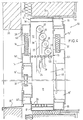
- the wall opening 33 extends to the floor 41 of the room and the installation frame 10 is extended downwards by an additional frame part 10 ', which has the same depth.
- a frame 42 In front of the lower frame part 10 'there is a frame 42, which is fixedly attached to the installation frame 10, 10' and contains a fixed panel 43.
- the frame part 10 'of the installation frame 10, 10' is closed to the inside of the building with a further cover 44.
- an air conditioner 46 with, for example, a humidifier, electrical drives, lines, control devices or other parts is accommodated.
- the space 45 can also contain an air inlet opening in connection with the interior of the building for sucking in cold ambient air, which is either returned to the room after heating or first fed to the window space 11 for heating and then introduced back into the interior of the building.
- the aperture 44 contains an opening 47 which connects the building space with the space 45, so that air from the building space can reach the air conditioner 46. In this way, decentralized ventilation with heat recovery is possible.
- a channel 48 leads from the room 45 into the window room 11, so that the film webs 29 can also be used as an air collector.
- a slot-shaped air inlet opening 50 is provided at the upper end of the space 45 in the panel 44, which extends over the entire width of the panel.
- the room air sucked in as a result is to be circulated, cleaned, partially exchanged for fresh air and heated or cooled. Possibly.
- an additional one in FIG. 7 cannot Air humidification device shown may be provided.
- the room air flow sucked in through the air inlet opening 50 is introduced into a main duct 56, which in cross section is essentially matched to the rectangular air inlet opening 50 and from which a partial air flow is directed via a branch line 51 into an exhaust air / fresh air heat exchanger 52.
- the exhaust air / fresh air heat exchanger 52 has independent blower units, not shown in FIG. 7, which each promote an equal air volume flow.
- the partial air flow which is branched off for exchange for fresh air can be regulated via a controller which can be operated on the orifice 44 and, if necessary, can be switched off completely.
- the heat exchanger enables a constant fresh air supply even in winter without having to accept excessive heat losses.
- the warmed-up fresh air is conducted via a line 55 leading away from the heat exchanger 52 together with the room air flowing in via the main duct 56 into a cavity above an air filter 57 and mixed there with the room air.
- the pipeline 55 can run in such a way that the fresh air, bypassing the air filter 57 and a blower unit 58, is led directly to a heating device 59 and is only mixed with the room air there.
- the duct 48 which leads into the window space 11, can optionally open into the cavity in front of the air filter 57, so that air heated by solar radiation can be extracted from the window space 11 serving as an air collector and for heating the indoor air can be used.
- a bore 67 is provided in the cross strut 151 in the window area for the supply of fresh air, which connects the building space to the window space 11.
- a channel 66 fastened to the side wall 20 leads into the window space 11.
- the channel 66 is arranged on the one lateral edge of the curtain sheets 29 at right angles to these and directly below the intermediate wall 13.
- the channel 66 has one or more openings which are directed towards the air chambers 30 of the curtain sheet 29 and which immediately replace the air drawn off via the channel 48 at the lower end of the curtain sheet 29 from the building space.
- the air chambers 30 are suctioned off via a further channel 68 which essentially corresponds to the channel 66, and the heated air is fed to the channel 48.
- the channel 68 is fastened to the side wall 20 at the level of the inner wall 23 and its openings are directed towards the air chambers 30 in order to extract the air.
- the webs 22 are extended beyond the inner wall 23 upwards.
- the duct 48 is connected, which can be closed, for example, by means of a throttle valve which can be set on the diaphragm 44, so that the hot air extraction in the window space 11 can be switched on as required and directed to the air filter 57.
- the air filter 57 consists, for example, of a nonwoven fabric supported on a pull-out wire rack and extends parallel to the floor over the entire width and depth of the space 45 in order to obtain a low filter inflow speed.
- the air to be circulated is constantly cleaned by the air filter 57, so that considerably less air dust, e.g. can settle on the furniture.
- a fan unit 58 e.g. a radial fan that generates negative pressure on the air filter 57 and thus finally also on the air inlet opening 50 and on the duct 48.
- the room air After flowing through the air filter 57, during which the room air is cleaned of dust particles, the room air enters the suction side of the blower unit 58, which directs the room air flow to be circulated into a heating device 59, e.g. promotes a convector that delivers its output essentially depending on the intensity of the convection flow.
- the blower unit 58 is thermostatically controlled via a room thermostat, which advantageously enables individual temperature control for each room in connection with the air conditioner 46.
- the conventor 59 can be connected to a conventional hot water heating system or can also be operated with a subcooled medium for cooling, for example.
- the convector 59 has the advantage over conventional radiators that it does not have any significant radiation losses. To regulate the heating or cooling output given, it also does not require any control valves which can cause flow noises, since the regulation takes place via the speed of the blower unit. In order to accommodate more heating surface in the available space 45, the convector can be installed at an angle to its longitudinal axis.
- Both a heating and a cooling device can be provided, the air guidance of the room air conveyed by the blower unit 58 optionally taking place, e.g. in summer operation via the cooling device and in winter operation via the heating device.
- an electrically operated heating or cooling device can also be provided, so that in such a case installation connections for the heating or cooling medium can be omitted.
- the room air passes under the convector 59 arranged parallelepiped-shaped channel 60, which extends over the entire width and depth of the installation frame 10 'and to which a horizontally extending parallelepiped-shaped channel section 61 leading into the building space connects.
- This channel section 61 runs below the floor, also extends over the entire width of the installation frame 10 'and is preferably arranged between an insulation layer 62 of the floor construction and the screed 63.
- At the end of the horizontal channel section 61 there is a slot-shaped, vertically upward air outlet opening 64, which likewise extends over the entire width of the installation frame 10 'and via which the circulated, cleaned and heated or cooled room air is recirculated at a low flow rate.
- the outlet opening 64 is expediently provided with a grate that can be walked on.
- the horizontal channel section 61 extends so far into the room that the air outlet opening 64 is in front and the outflowing room air is usually in front.
- the window attached curtains 65 seen from the building room in front of the curtains 65 freely in the building room at the lowest possible point. This has the advantage that a heat cushion between curtain 65 and window does not form between curtain 65 and the window, as in conventional space heaters with radiators under the windows, which leads to increased heat losses at the window surfaces. Rather, a cool air cushion is formed between the window and the curtain 65, which hardly circulates and is therefore highly insulating and therefore enables considerably less heat loss at the window.
- the aperture 44 is advantageously designed to be removable, so that all installation devices in the room 45 are freely accessible, which is also important, for example, for changing the filter.
- the heat transfer medium of the heater can flow continuously through the convector.
- the heating power is regulated with the blower unit 58 via a room thermostat. Even when the blower unit 58 is at a standstill due to regulation, there remains a residual heating in the amount of approximately 100/0 of the maximum heating power, which can serve the fresh air portion which continues to flow through the air conditioning unit 46 due to the independent blower units in the heat exchanger 52 even when the blower unit 58 is at a standstill to heat up additionally.
- the cooling device in the summer, can be continuously flowed through by the cooling medium, the cooling capacity essentially being dependent on the room air circulation speed.
- the blower unit 58 When the blower unit 58 is at a standstill, the residual cooling is sufficient to cool the fresh air portion.
- the advantages of the air conditioner described are the low installation costs, the quick controllability of the heating or cooling capacity and thus the possibility of adaptation between day and night, between radiation-intensive weather conditions and overcast weather conditions and in the individual climate control for each building room.
- the air conditioner described also enables fresh air to be supplied without the otherwise usual disadvantages of cold air in cold seasons and without drafts.
- the air-conditioning unit described is very space-saving and, in particular in connection with the heat-insulating window, is very advantageous in that air heated from the window space 11 is used for heating during the heating period.
- the air conditioning unit described can be easily retrofitted, the air outlet opening 64 being arranged directly at the baseboard height in cases in which the duct section 61 cannot be let into the floor 41.
- the air conditioning unit 46 is installed in an essentially L-shaped modular housing which can be installed in an installation frame 10 'in the simplest way. This has the advantage that only the installation frame 10, 10 ', e.g. for an insulating window with air conditioner 46 must be installed, but the decision on the individual air conditioning units of air conditioner 46 or on the window designs must be made at the end.
- the common installation frame 10, 10 enables, in particular, the simple combination of the heat-insulating window with an air conditioner 46, so that the window can be used as an air collector when the sun is shining.
- the air conditioner 46 can also be installed in an installation frame 10 'surrounding only the vertical part of the L-shaped housing if no windows are provided on the corresponding wall.
Landscapes
- Engineering & Computer Science (AREA)
- Structural Engineering (AREA)
- Civil Engineering (AREA)
- Combustion & Propulsion (AREA)
- Life Sciences & Earth Sciences (AREA)
- Mechanical Engineering (AREA)
- General Engineering & Computer Science (AREA)
- Architecture (AREA)
- Chemical & Material Sciences (AREA)
- Sustainable Development (AREA)
- Load-Bearing And Curtain Walls (AREA)
- Building Environments (AREA)
- Blinds (AREA)
- Special Wing (AREA)
- Refrigerator Housings (AREA)
- Door And Window Frames Mounted To Openings (AREA)
- Thermally Insulated Containers For Foods (AREA)
- Glass Compositions (AREA)
- Insulated Conductors (AREA)
Claims (19)
caractérisée en ce que le cadre dormant (14) est fixé à un cadre d'installation (10) qui est relié à la paroi (32), qui est disposé sur tout le périmètre à l'intérieur de l'ouverture de la paroi (33) et qui contient l'espace fenêtre (11) et l'espace auxiliaire (12).
étant précisé qu'une ouverture de sortie d'air, côté espace, (64), est disposée dans le plan du plancher, à l'extrémité d'une portion de canal (61), qui parcourt l'aile horizontale du carter.
Priority Applications (4)
| Application Number | Priority Date | Filing Date | Title |
|---|---|---|---|
| AT84101824T ATE27724T1 (de) | 1983-11-17 | 1984-02-22 | Waermedaemmendes fenster. |
| DE19848427231 DE8427231U1 (de) | 1984-02-22 | 1984-09-15 | Raumklimatisierungsgeraet |
| AU35227/84A AU572223B2 (en) | 1983-11-17 | 1984-11-08 | Heat insulating window |
| CA000467410A CA1256744A (fr) | 1983-11-17 | 1984-11-08 | Fenetre thermo-isolante |
Applications Claiming Priority (2)
| Application Number | Priority Date | Filing Date | Title |
|---|---|---|---|
| DE19833341485 DE3341485A1 (de) | 1983-11-17 | 1983-11-17 | Waermedaemmendes fenster |
| DE3341485 | 1983-11-17 |
Publications (2)
| Publication Number | Publication Date |
|---|---|
| EP0142596A1 EP0142596A1 (fr) | 1985-05-29 |
| EP0142596B1 true EP0142596B1 (fr) | 1987-06-10 |
Family
ID=6214501
Family Applications (1)
| Application Number | Title | Priority Date | Filing Date |
|---|---|---|---|
| EP84101824A Expired EP0142596B1 (fr) | 1983-11-17 | 1984-02-22 | Fenêtre calorifuge |
Country Status (5)
| Country | Link |
|---|---|
| EP (1) | EP0142596B1 (fr) |
| JP (1) | JPS60144489A (fr) |
| AT (1) | ATE27724T1 (fr) |
| DE (1) | DE3464147D1 (fr) |
| ZA (1) | ZA848507B (fr) |
Families Citing this family (5)
| Publication number | Priority date | Publication date | Assignee | Title |
|---|---|---|---|---|
| JPS6232183U (fr) * | 1985-08-12 | 1987-02-26 | ||
| DE3837428A1 (de) * | 1988-11-04 | 1990-05-10 | Fraunhofer Ges Forschung | Vorrichtung zur vermeidung der konvektion im zwischenraum von doppelverglasungen oder doppelwandigen bauteilen |
| GB9824861D0 (en) * | 1998-11-13 | 1999-01-06 | Mckenzie Martin A | 2-Type vertical rail adaptations |
| JP6548252B2 (ja) * | 2015-06-09 | 2019-07-24 | 公一郎 小山 | 窓構造体 |
| CN107816747B (zh) * | 2017-11-29 | 2023-08-04 | 合肥恒暖暖通设备有限公司 | 一种门窗套采暖散热器及其安装使用方法 |
Family Cites Families (5)
| Publication number | Priority date | Publication date | Assignee | Title |
|---|---|---|---|---|
| US3961659A (en) * | 1974-10-10 | 1976-06-08 | Helmut Siegel | Prefabricated window unit |
| DE2749037C2 (de) * | 1977-11-02 | 1983-12-08 | Josef Gartner & Co, 8883 Gundelfingen | Fenster, insbesondere Gebäudefenster |
| DE3026635A1 (de) * | 1978-02-27 | 1982-02-11 | Schmidt Reuter Ingenieurgesellschaft mbH & Co KG, 5000 Köln | Luftfuehrende fassade |
| DE2922441C2 (de) * | 1979-06-01 | 1985-10-17 | Heinrich Dipl.-Ing. 5205 St Augustin Hilbers | Induktionsgerät zur Belüftung von Aufenthaltsräumen |
| DE3112394A1 (de) * | 1980-07-22 | 1982-07-08 | Eltreva AG, 4147 Aesch | "einrichtung zur luftregulierung einer energiefassade" |
-
1984
- 1984-02-22 DE DE8484101824T patent/DE3464147D1/de not_active Expired
- 1984-02-22 EP EP84101824A patent/EP0142596B1/fr not_active Expired
- 1984-02-22 AT AT84101824T patent/ATE27724T1/de not_active IP Right Cessation
- 1984-10-31 ZA ZA848507A patent/ZA848507B/xx unknown
- 1984-11-16 JP JP59240862A patent/JPS60144489A/ja active Pending
Also Published As
| Publication number | Publication date |
|---|---|
| JPS60144489A (ja) | 1985-07-30 |
| EP0142596A1 (fr) | 1985-05-29 |
| ZA848507B (en) | 1985-06-26 |
| DE3464147D1 (en) | 1987-07-16 |
| ATE27724T1 (de) | 1987-06-15 |
Similar Documents
| Publication | Publication Date | Title |
|---|---|---|
| DE19534843C2 (de) | Rolladenaggregat | |
| EP0169918B1 (fr) | Fenêtre isolante thermiquement | |
| DE2702214A1 (de) | Verbundfenster | |
| EP0044560A2 (fr) | Installation d'aérage pour des espaces ventilés en circulation forcée | |
| EP3320275B1 (fr) | Module de fenêtre actif servant à la régulation thermique d'un bâtiment, et procédé | |
| EP0164111B1 (fr) | Fenêtre composée insonorisante et calorifuge avec un dispositif d'aération | |
| DE2754166A1 (de) | Heizungs- und klimatisierungsanlage | |
| DE3043783A1 (de) | Schall- und waermeisolierendes verbundfenster mit verstellbarer schalldaemmlueftung | |
| EP0177657B1 (fr) | Système pour assurer la demande d'énergie d'un local | |
| DE202006020354U1 (de) | Temperatur-, Wärme- und/oder Kältebarriere insbesondere für oder in einer Vorrichtung zur Klimatisierung von Gebäuden | |
| DE19635466A1 (de) | Gebäude mit vorgehängter Glasfassade | |
| EP0142596B1 (fr) | Fenêtre calorifuge | |
| DE3216581A1 (de) | Schall- und waermeisolierendes verbundfenster mit schalldaemmlueftung | |
| EP0951630B1 (fr) | Procede d'aeration d'un local et dispositif pour mettre en oeuvre ledit procede | |
| EP0112572A1 (fr) | Cadre pour portes ou fenêtres et caisse, plus spécialement caisse de volet, placée au dessus du cadre | |
| DE3026635A1 (de) | Luftfuehrende fassade | |
| DE3728698A1 (de) | Klimaanlage | |
| DE3248227A1 (de) | Umlaufende einfassung fuer tueren oder fenster, sowie kastenbauteil, insbesondere rolladenkasten, zur verwendung oberhalb der einfassung | |
| WO2009027049A1 (fr) | Système d'aération de façade | |
| DE8713390U1 (de) | Lüftungsgerät zum Abführen von Abluft aus Räumen | |
| DE19963919A1 (de) | Verfahren und Einrichtung zum wärmeverlustarmen Belüften von Räumen über eine oder mehrere Fenster/Tür-Rollladenanordnungen | |
| DE7701569U1 (de) | Verbundfenster | |
| DE19816177C1 (de) | Solar-Luft-Kollektor in Fenstersystemtechnik | |
| EP0358121A2 (fr) | Fenêtre aérée | |
| DE29615791U1 (de) | Zweischalige Gebäudefassade |
Legal Events
| Date | Code | Title | Description |
|---|---|---|---|
| PUAI | Public reference made under article 153(3) epc to a published international application that has entered the european phase |
Free format text: ORIGINAL CODE: 0009012 |
|
| AK | Designated contracting states |
Designated state(s): AT BE CH DE FR GB IT LI LU NL SE |
|
| 17P | Request for examination filed |
Effective date: 19850831 |
|
| 17Q | First examination report despatched |
Effective date: 19860513 |
|
| GRAA | (expected) grant |
Free format text: ORIGINAL CODE: 0009210 |
|
| AK | Designated contracting states |
Kind code of ref document: B1 Designated state(s): AT BE CH DE FR GB IT LI LU NL SE |
|
| REF | Corresponds to: |
Ref document number: 27724 Country of ref document: AT Date of ref document: 19870615 Kind code of ref document: T |
|
| ITF | It: translation for a ep patent filed | ||
| RAP2 | Party data changed (patent owner data changed or rights of a patent transferred) |
Owner name: WEIBLEN, ROLF-DIETHER |
|
| REF | Corresponds to: |
Ref document number: 3464147 Country of ref document: DE Date of ref document: 19870716 |
|
| ET | Fr: translation filed | ||
| PLBE | No opposition filed within time limit |
Free format text: ORIGINAL CODE: 0009261 |
|
| STAA | Information on the status of an ep patent application or granted ep patent |
Free format text: STATUS: NO OPPOSITION FILED WITHIN TIME LIMIT |
|
| 26N | No opposition filed | ||
| ITTA | It: last paid annual fee | ||
| PGFP | Annual fee paid to national office [announced via postgrant information from national office to epo] |
Ref country code: SE Payment date: 19920214 Year of fee payment: 9 |
|
| PGFP | Annual fee paid to national office [announced via postgrant information from national office to epo] |
Ref country code: GB Payment date: 19920218 Year of fee payment: 9 |
|
| PGFP | Annual fee paid to national office [announced via postgrant information from national office to epo] |
Ref country code: LU Payment date: 19920225 Year of fee payment: 9 |
|
| PGFP | Annual fee paid to national office [announced via postgrant information from national office to epo] |
Ref country code: FR Payment date: 19920227 Year of fee payment: 9 |
|
| PGFP | Annual fee paid to national office [announced via postgrant information from national office to epo] |
Ref country code: BE Payment date: 19920303 Year of fee payment: 9 |
|
| EPTA | Lu: last paid annual fee | ||
| PG25 | Lapsed in a contracting state [announced via postgrant information from national office to epo] |
Ref country code: LU Free format text: LAPSE BECAUSE OF NON-PAYMENT OF DUE FEES Effective date: 19930222 Ref country code: GB Effective date: 19930222 |
|
| PG25 | Lapsed in a contracting state [announced via postgrant information from national office to epo] |
Ref country code: SE Effective date: 19930223 |
|
| PGFP | Annual fee paid to national office [announced via postgrant information from national office to epo] |
Ref country code: AT Payment date: 19930224 Year of fee payment: 10 |
|
| PGFP | Annual fee paid to national office [announced via postgrant information from national office to epo] |
Ref country code: CH Payment date: 19930226 Year of fee payment: 10 |
|
| PG25 | Lapsed in a contracting state [announced via postgrant information from national office to epo] |
Ref country code: BE Effective date: 19930228 |
|
| PGFP | Annual fee paid to national office [announced via postgrant information from national office to epo] |
Ref country code: NL Payment date: 19930228 Year of fee payment: 10 |
|
| BERE | Be: lapsed |
Owner name: WEIBLEN ROLF-DIETHER Effective date: 19930228 |
|
| GBPC | Gb: european patent ceased through non-payment of renewal fee |
Effective date: 19930222 |
|
| PG25 | Lapsed in a contracting state [announced via postgrant information from national office to epo] |
Ref country code: FR Effective date: 19931029 |
|
| REG | Reference to a national code |
Ref country code: FR Ref legal event code: ST |
|
| PG25 | Lapsed in a contracting state [announced via postgrant information from national office to epo] |
Ref country code: AT Effective date: 19940222 |
|
| PG25 | Lapsed in a contracting state [announced via postgrant information from national office to epo] |
Ref country code: LI Effective date: 19940228 Ref country code: CH Effective date: 19940228 |
|
| PG25 | Lapsed in a contracting state [announced via postgrant information from national office to epo] |
Ref country code: NL Effective date: 19940901 |
|
| NLV4 | Nl: lapsed or anulled due to non-payment of the annual fee | ||
| REG | Reference to a national code |
Ref country code: CH Ref legal event code: PL |
|
| EUG | Se: european patent has lapsed |
Ref document number: 84101824.5 Effective date: 19930912 |
|
| PGFP | Annual fee paid to national office [announced via postgrant information from national office to epo] |
Ref country code: DE Payment date: 20010223 Year of fee payment: 18 |
|
| PG25 | Lapsed in a contracting state [announced via postgrant information from national office to epo] |
Ref country code: DE Free format text: LAPSE BECAUSE OF NON-PAYMENT OF DUE FEES Effective date: 20020903 |