EP0142598A2 - Dispositif d'évacuation des condensats dans les condenseurs de vapeur échangeurs de chaleur - Google Patents
Dispositif d'évacuation des condensats dans les condenseurs de vapeur échangeurs de chaleur Download PDFInfo
- Publication number
- EP0142598A2 EP0142598A2 EP84104541A EP84104541A EP0142598A2 EP 0142598 A2 EP0142598 A2 EP 0142598A2 EP 84104541 A EP84104541 A EP 84104541A EP 84104541 A EP84104541 A EP 84104541A EP 0142598 A2 EP0142598 A2 EP 0142598A2
- Authority
- EP
- European Patent Office
- Prior art keywords
- condensate
- steam
- heat exchanger
- buffer tank
- line
- Prior art date
- Legal status (The legal status is an assumption and is not a legal conclusion. Google has not performed a legal analysis and makes no representation as to the accuracy of the status listed.)
- Withdrawn
Links
Images


Classifications
-
- F—MECHANICAL ENGINEERING; LIGHTING; HEATING; WEAPONS; BLASTING
- F22—STEAM GENERATION
- F22D—PREHEATING, OR ACCUMULATING PREHEATED, FEED-WATER FOR STEAM GENERATION; FEED-WATER SUPPLY FOR STEAM GENERATION; CONTROLLING WATER LEVEL FOR STEAM GENERATION; AUXILIARY DEVICES FOR PROMOTING WATER CIRCULATION WITHIN STEAM BOILERS
- F22D11/00—Feed-water supply not provided for in other main groups
-
- F—MECHANICAL ENGINEERING; LIGHTING; HEATING; WEAPONS; BLASTING
- F28—HEAT EXCHANGE IN GENERAL
- F28B—STEAM OR VAPOUR CONDENSERS
- F28B9/00—Auxiliary systems, arrangements, or devices
- F28B9/08—Auxiliary systems, arrangements, or devices for collecting and removing condensate
Definitions
- the relevant temperature is usually above the setpoint temperature of the medium to be heated and, as treated boiler water, can destroy stoneware pipes and concrete.
- the sudden increase in heating costs for steam generation requires an unproblematic technology that, with little investment, brings about the best possible efficiency of the systems in question.
- This is achieved according to the invention by storing part of the inert gas carried in the steam, for example air, via the condensate disposal of the heat exchanger in a container which is sucked into and / or pressed into the steam space of the heat exchanger if necessary, or by using a non-condensable gas greater density than water vapor in the vapor space of a heat exchanger, possibly fed from an existing operating network.
- the inflowing air is classified according to the basic physical laws - water vapor is lighter and water heavier than air - between steam and condensate and thus causes a condensate disposal via the control fittings, which is ensured at every operating point and every installation position.
- Other significant advantages are: steam cannot cool down on the condensate; the non-condensable inert gas acts as insulation (in the area where steam meets the accumulated condensate, the steam bubbles condense spontaneously. The sudden condensation of the steam bubbles due to the trailing, supercooled condensate causes considerable forces which cause the magnetite layer of the jacket pipes to stop attack replacement tubes and tube sheets in this area of the heat exchanger).
- Condensate can be lifted without additional energy and, depending on the steam pressure, fed into a pressure condensate line.
- the required design for heat exchangers results in small, compact buffer tanks that already fit each existing problem system can be retrofitted.
- the containers can be manufactured in such a way that additional volume can be flanged on, which means that several heat exchangers can be operated.
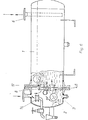
- a hydrostatic pressure of 0.28 bar acts on the ventilated buffer tank - 1 - from the condensate manifold, which is vented and relieved via a central energy recovery system. If the vapor pressure in the heat exchanger falls below 0.28 bar, the inert gas (air) is pressed from the buffer tank - 1 - via the control line and non-return valve - 8 - via the condensate sump - 3 - and the sight glass - 13 - into the steam chamber of the heat exchanger / and sucked. Condensate flows from the one loaded with cargo Collection line via the shut-off valve with delivery line - 6 - back into the buffer tank - 1 -.
- the condensate disposal from the heat exchanger - 11 - via sight glass - 13 - condensate sump - 3 - and float steam traps - 4 - with built-in thermal vent - 2 - can be carried out unhindered during this process. If the steam pressure in the heat exchanger - 11 - rises again (higher heat output is required), the inert gas is increased to 70 ° C via sight glass - 13 - condensate sump - 3 - and the thermal vent valve - 2 - to avoid re-steaming in the buffer tank Closing temperature is set, pushed back into the buffer tank - 1 - via the gas control line.
- This process can be repeated any number of times, the inert gas of the steam is stored in the buffer tank, the volume of which should contain at least the volume of the steam chamber of the heat exchanger.
- the heat exchanger In the case of a flooded buffer tank (leaking heating system), the heat exchanger would draw in the necessary amount of residual air if necessary via the valve with a vacuum breaker - 14 - which is open at bore - e.
- the steam chamber of the heat exchanger can work in excess pressure with respect to the condensate drain line - 6. This causes the air in the steam chamber to be pressed into the float housing from the steam trap - 4,2,13- via bore - a -, from there via the built-in thermal vent - 2 - and the cooling coil through the overflow valve - 15 - set with ⁇ P becomes.
- the pressure setting of the overflow valve - 15 - depends on the working pressure of the steam trap at the maximum amount of condensate flow in the heating system. For example, an arrester requires a working pressure of 0.17 bar to dispose of 470 kg / h condensate.
- the overflow valve - 15 - set to 0.2 bar ⁇ P from the steam chamber of the heat exchanger to the buffer tank - 1 - causes the drain trap - 4 - to work properly, to be checked via the built-in sight glass - 13 -.
- the vent valve - 18 - with immersion nozzle disposes of the inert that accumulates over the required storage volume gas from the buffer tank - 1 - into the atmosphere.
- the immersion connection of the supply line - 6 - should be arranged lower than the immersion connection of the vent valve - 18 -.
- FIG. 3 shows another form of the gas charger, as can be used to operate an air conditioning heating register.
- - 11 - shows a register with an overhead steam distributor, welded-in replacement pipes with fins and a condensate collecting space underneath.
- the register - 11 - is filled with inert gas and the buffer tank - 1 - with condensate.
- the inflowing steam displaces the air from top to bottom from the register - 11 - depending on the required heating output. This will result the amounts of condensate pressed by the air via the float ladder - 4,2,8 - into the buffer tank - 1 - fed. At the same time, the air displaced by the steam is forced into the buffer tank - 1 - via the thermal ventilation - 2 - of the arrester - 4. The air space required there is released by the condensate, which escapes through the immersion tube - 6. The air is compressed via the hydrostatic pressure of the water column or pressure in the condensate network.
- the inert gas is passed from the breather - 17 - into the overflow chamber - 16 - and from there via the non-return valve - 8 - into the steam distribution space from the heating register - 11 -.
- the steam-air mixture has a lower calorific value than pure steam, so more heating surface is used for a certain setpoint.
- the resulting amounts of condensate can, for. B. with external condensate together in the heat exchanger - 20 - cooled down to the actual temperature of the medium to be heated.
- the ventilation line - 19 - removes the heat exchanger - 20 - from the inert gas of the external condensate, which is also stored in the buffer tank and can be disposed of into the atmosphere via the ventilation valve - 18 - if necessary. Process and foreign condensate can be fed into the condensate network unhindered, cooled, degassed and without secondary energy.
- Fig. 5 shows a gas charger for the operation of several heat exchangers - steam condensers with the most varied setpoints and physical states of the to be heated Wedien.
- the buffer tank - 1 - is designed with flange connections on the tube sheets, the left tube sheet was removed by a straight piece of tube - 21 - extended with a total volume of four steam condensers.
- the float steam traps - 4,2 - are flanged to the welded pipe socket of pipe section - 21.
- the thermal breather or steam accumulator - 2 - feed into the buffer space of the gas charger.
- the breather - 17 - with overflow line and vacuum breaker - 14 - can be matched to the suction capacity of four heat exchangers.
- the fittings - 8 - 2 - 4.2 - must be matched to the individual steam condensers.
- Fig. 6 shows a gas charger, in which the necessary control fittings are mounted on a metal disc, separate the buffer tank - 1 - from the condensate sump - 3.
- the steam trap - 4 - is equipped with a non-return valve - 8 -.
- the air vent and steam accumulator - 2 - is also designed as a non-return valve - 8 -.
- the breather - 17 - is also equipped with a non-return valve, flow direction to the heat exchanger.
- the vacuum breaker - 14 - is here integrated in the condensate sump - 3 - and, as with the other versions, can be used as a nitrogen feed or dql. serve.
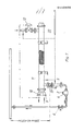
- FIG. 7 shows a heat exchanger which is supplied with nitrogen via an operating network 22.
- the feed can take place in the heating steam, upstream of the control valve - 12 -, in the steam room - 11 - directly, in the flanged condensate sump - 3 -, or with a suitable float steam trap - 4 -, in the relevant float chamber.
- the inert gas is preferably to be fed into the condensate sump in order to prevent an inert gas / vapor mixture if the heating process requires this.
- heating steam 1.75 bar (Ü) T 130 ° C - with 10% inert gas, the steam temperature is 127 ° C - with 30% the temperature drops to 119 ° C).
- an inert gas pressure of the operating network - 22 - of 0.21 bar (U) is sufficient to remove the condensate from the heat exchanger at every operating point.
- the required boost pressure can in any case be set via the sight glass - 13 -.
- inert gas can also be fed into the vapor space with excess pressure.
- small quantities of up to 10 l / h are sufficient.
Landscapes
- Engineering & Computer Science (AREA)
- Mechanical Engineering (AREA)
- General Engineering & Computer Science (AREA)
- Water Supply & Treatment (AREA)
- Physics & Mathematics (AREA)
- Thermal Sciences (AREA)
- Processing Of Solid Wastes (AREA)
- Pipeline Systems (AREA)
- Apparatus For Disinfection Or Sterilisation (AREA)
Applications Claiming Priority (2)
| Application Number | Priority Date | Filing Date | Title |
|---|---|---|---|
| DE19833341246 DE3341246C2 (de) | 1982-11-26 | 1983-11-15 | Kondensatentsorgungseinrichtung für temperaturgeregelte dampfbeaufschlagte Wärmetauscher |
| DE3341246 | 1983-11-15 |
Publications (2)
| Publication Number | Publication Date |
|---|---|
| EP0142598A2 true EP0142598A2 (fr) | 1985-05-29 |
| EP0142598A3 EP0142598A3 (fr) | 1987-03-11 |
Family
ID=6214347
Family Applications (1)
| Application Number | Title | Priority Date | Filing Date |
|---|---|---|---|
| EP84104541A Withdrawn EP0142598A3 (fr) | 1983-11-15 | 1984-04-21 | Dispositif d'évacuation des condensats dans les condenseurs de vapeur échangeurs de chaleur |
Country Status (2)
| Country | Link |
|---|---|
| EP (1) | EP0142598A3 (fr) |
| CA (1) | CA1226860A (fr) |
Cited By (4)
| Publication number | Priority date | Publication date | Assignee | Title |
|---|---|---|---|---|
| CN110220184A (zh) * | 2019-07-03 | 2019-09-10 | 天津市天元机械制造有限公司 | 一种锅炉蒸汽凝水回收装置 |
| CN110284289A (zh) * | 2019-07-18 | 2019-09-27 | 上海航星机械(集团)有限公司 | 一种熨平机的排水装置及排水方法 |
| CN114659092A (zh) * | 2022-03-18 | 2022-06-24 | 灵谷化工集团有限公司 | 一种除氧器乏汽放空回收装置及其回收方法 |
| CN119123408A (zh) * | 2024-10-31 | 2024-12-13 | 中国船舶集团有限公司第七〇四研究所 | 一种应用于石油平台的撬装式除氧器 |
Family Cites Families (5)
| Publication number | Priority date | Publication date | Assignee | Title |
|---|---|---|---|---|
| BE353816A (fr) * | ||||
| GB270378A (en) * | 1926-02-02 | 1927-05-02 | English Electric Co Ltd | Improvements in condensing plant for steam and other vapours |
| US2350197A (en) * | 1941-02-28 | 1944-05-30 | Gen Electric | Elastic fluid power plant |
| DE821949C (de) * | 1950-06-28 | 1951-11-22 | Horst Hesse Dr Ing | Kondensatabscheider an Druckgefaessen |
| US4165718A (en) * | 1977-10-12 | 1979-08-28 | Chen Thomas Y C | Method and apparatus for feeding condensate to a high pressure vapor generator |
-
1984
- 1984-04-21 EP EP84104541A patent/EP0142598A3/fr not_active Withdrawn
- 1984-05-31 CA CA000455525A patent/CA1226860A/fr not_active Expired
Cited By (7)
| Publication number | Priority date | Publication date | Assignee | Title |
|---|---|---|---|---|
| CN110220184A (zh) * | 2019-07-03 | 2019-09-10 | 天津市天元机械制造有限公司 | 一种锅炉蒸汽凝水回收装置 |
| CN110284289A (zh) * | 2019-07-18 | 2019-09-27 | 上海航星机械(集团)有限公司 | 一种熨平机的排水装置及排水方法 |
| CN110284289B (zh) * | 2019-07-18 | 2023-09-12 | 上海航星机械(集团)有限公司 | 一种熨平机的排水装置及排水方法 |
| CN114659092A (zh) * | 2022-03-18 | 2022-06-24 | 灵谷化工集团有限公司 | 一种除氧器乏汽放空回收装置及其回收方法 |
| CN114659092B (zh) * | 2022-03-18 | 2024-04-19 | 灵谷化工集团有限公司 | 一种除氧器乏汽放空回收装置及其回收方法 |
| CN119123408A (zh) * | 2024-10-31 | 2024-12-13 | 中国船舶集团有限公司第七〇四研究所 | 一种应用于石油平台的撬装式除氧器 |
| CN119123408B (zh) * | 2024-10-31 | 2025-12-30 | 中国船舶集团有限公司第七〇四研究所 | 一种应用于石油平台的撬装式除氧器 |
Also Published As
| Publication number | Publication date |
|---|---|
| CA1226860A (fr) | 1987-09-15 |
| EP0142598A3 (fr) | 1987-03-11 |
Similar Documents
| Publication | Publication Date | Title |
|---|---|---|
| CA2158595C (fr) | Condenseur avec element de vidange pour reduire le volume de liquide a l'interieur du reservoir | |
| DE102008001308B3 (de) | Wärmeenergiemanagement für Produktionsanlagen | |
| EP3911907B1 (fr) | Dispositif et procédé pour la récupération de chaleur d'un milieu liquide | |
| DE2306689A1 (de) | System fuer hydraulische durchflussverteilung bei luftgekuehlten waermeaustauschern mit mehreren wegen | |
| WO2024022606A1 (fr) | Système de refroidissement pour le refroidissement par immersion liquide de composants électroniques | |
| US4585054A (en) | Condensate draining system for temperature regulated steam operated heat exchangers | |
| EP1064954A1 (fr) | Stérilisateur à vapeur | |
| EP0142598A2 (fr) | Dispositif d'évacuation des condensats dans les condenseurs de vapeur échangeurs de chaleur | |
| US7975500B2 (en) | Refrigerant accumulation and oil recovery device for refrigerant fluid recovery/regeneration/recharging systems | |
| EP0327488B1 (fr) | Condenseur | |
| DE3507798A1 (de) | Verfahren zum transport von waerme in gebaeuden | |
| EP0215966B1 (fr) | Installation pour la récupération de la chaleur | |
| DE3341246A1 (de) | Einrichtung zur kondensatabfuehrung an dampfkondensatoren-waermetauschern | |
| DE3918593A1 (de) | Verfahren und anordnung zur abschaltung eines im abgasstrom eines verbrennungsmotors angeordneten, mit einem fliessfaehigen waermetraeger betriebenen waermetauschers | |
| DE102021212334A1 (de) | Wasseraufbereitungsanlage | |
| US2075784A (en) | Waste water heat recovery apparatus | |
| DE3044855C2 (de) | Wärmeübertragungsanlage | |
| DE4440036C2 (de) | Anordnung zum Wärmeaustausch | |
| WO2011073762A2 (fr) | Échangeur de chaleur | |
| DE3210350C2 (fr) | ||
| CN222266183U (zh) | 油气三级冷凝装置 | |
| DE69524414T2 (de) | Wärmerückgewinnungsanlage aus Fahrzeugabgasen | |
| DE3443762A1 (de) | Verfahren und anlage zur kondensation von ueberschussdampf | |
| DE69712171T2 (de) | Kompakte Vorrichtung zur Regeneration von Lösemitteln | |
| CN215886437U (zh) | 一种冷凝水回收设备及循环水冷却系统 |
Legal Events
| Date | Code | Title | Description |
|---|---|---|---|
| PUAI | Public reference made under article 153(3) epc to a published international application that has entered the european phase |
Free format text: ORIGINAL CODE: 0009012 |
|
| AK | Designated contracting states |
Designated state(s): BE CH FR GB IT LI NL SE |
|
| RTI1 | Title (correction) | ||
| PUAL | Search report despatched |
Free format text: ORIGINAL CODE: 0009013 |
|
| AK | Designated contracting states |
Kind code of ref document: A3 Designated state(s): BE CH FR GB IT LI NL SE |
|
| 17P | Request for examination filed |
Effective date: 19870331 |
|
| 17Q | First examination report despatched |
Effective date: 19870825 |
|
| STAA | Information on the status of an ep patent application or granted ep patent |
Free format text: STATUS: THE APPLICATION IS DEEMED TO BE WITHDRAWN |
|
| 18D | Application deemed to be withdrawn |
Effective date: 19880105 |
|
| RIN1 | Information on inventor provided before grant (corrected) |
Inventor name: KOEPRUNNER, ERNST |