EP0142687B1 - Appareil de lubrification de chaîne - Google Patents
Appareil de lubrification de chaîne Download PDFInfo
- Publication number
- EP0142687B1 EP0142687B1 EP84111889A EP84111889A EP0142687B1 EP 0142687 B1 EP0142687 B1 EP 0142687B1 EP 84111889 A EP84111889 A EP 84111889A EP 84111889 A EP84111889 A EP 84111889A EP 0142687 B1 EP0142687 B1 EP 0142687B1
- Authority
- EP
- European Patent Office
- Prior art keywords
- chain
- lubricant
- lubrication
- pump
- coupling
- Prior art date
- Legal status (The legal status is an assumption and is not a legal conclusion. Google has not performed a legal analysis and makes no representation as to the accuracy of the status listed.)
- Expired
Links
- 230000001050 lubricating effect Effects 0.000 title claims abstract description 15
- 238000005461 lubrication Methods 0.000 claims abstract description 69
- 239000000314 lubricant Substances 0.000 claims abstract description 48
- 239000003921 oil Substances 0.000 claims description 38
- 230000008878 coupling Effects 0.000 claims description 36
- 238000010168 coupling process Methods 0.000 claims description 36
- 238000005859 coupling reaction Methods 0.000 claims description 36
- 239000010687 lubricating oil Substances 0.000 claims description 11
- 210000000078 claw Anatomy 0.000 claims description 7
- 125000006850 spacer group Chemical group 0.000 claims description 3
- 230000000694 effects Effects 0.000 claims description 2
- 238000002347 injection Methods 0.000 claims 1
- 239000007924 injection Substances 0.000 claims 1
- 230000001550 time effect Effects 0.000 claims 1
- 230000001419 dependent effect Effects 0.000 abstract 1
- 238000006073 displacement reaction Methods 0.000 abstract 1
- 230000000737 periodic effect Effects 0.000 abstract 1
- 239000007921 spray Substances 0.000 description 7
- 230000001360 synchronised effect Effects 0.000 description 3
- 238000010586 diagram Methods 0.000 description 2
- 238000005507 spraying Methods 0.000 description 2
- 230000003247 decreasing effect Effects 0.000 description 1
- 238000000034 method Methods 0.000 description 1
- 230000001681 protective effect Effects 0.000 description 1
- 238000005086 pumping Methods 0.000 description 1
- 230000036962 time dependent Effects 0.000 description 1
- 230000001960 triggered effect Effects 0.000 description 1
Images


Classifications
-
- B—PERFORMING OPERATIONS; TRANSPORTING
- B65—CONVEYING; PACKING; STORING; HANDLING THIN OR FILAMENTARY MATERIAL
- B65G—TRANSPORT OR STORAGE DEVICES, e.g. CONVEYORS FOR LOADING OR TIPPING, SHOP CONVEYOR SYSTEMS OR PNEUMATIC TUBE CONVEYORS
- B65G45/00—Lubricating, cleaning, or clearing devices
- B65G45/02—Lubricating devices
- B65G45/08—Lubricating devices for chains
-
- F—MECHANICAL ENGINEERING; LIGHTING; HEATING; WEAPONS; BLASTING
- F16—ENGINEERING ELEMENTS AND UNITS; GENERAL MEASURES FOR PRODUCING AND MAINTAINING EFFECTIVE FUNCTIONING OF MACHINES OR INSTALLATIONS; THERMAL INSULATION IN GENERAL
- F16N—LUBRICATING
- F16N13/00—Lubricating-pumps
- F16N13/22—Lubricating-pumps with distributing equipment
Definitions
- the invention relates to a device for applying liquid lubricant in shots to a high-speed chain guided by a drive wheel with at least one lubricant outlet nozzle directed against the chain, to which lubricant is supplied by means of at least one cam-actuated lubricant piston pump, each lubricant delivery point having a fixed lubricant piston pump is assigned, with one or more control cams which are carried by a common, axially movable coupling shaft which can be coupled to a drive shaft and a sensor which emits a signal which effects the coupling and uncoupling of the shaft and lubrication of the chain.
- a lubricating device of this type is known from US-A-4 085 821.
- Lubrication of a chain is triggered there by a contact arm, which is pressed down by the hinge pins of the rotating chain and actuates a signal-triggering switch.
- the signal causes a clutch engagement process that connects a motor shaft to a pump shaft.
- the pump shaft has eccentrics, each of which moves a piston upward against the force of a return spring in a lubricant pump when the shaft is rotated, the amount of lubricant in the pump being fed via a line to the lubricant delivery point.
- the lubricating device can only be used for very slow-running chains, since the electric motor driving the pump shaft cannot be synchronized with the running of the chain as required and cannot be adapted to continuously changing chain speeds, so that a targeted application of a limited amount of lubricant to one certain lubrication point is not possible.
- EP-A-63 446 has disclosed a device for lubricating chains, in which the lubricating units and the tank are arranged on a rotating disk or wheel.
- Such lubrication devices are, however, completely unsuitable for lubricating a large number of lubrication points with the smallest amounts of lubricant, since the lubrication units are subject to very large rotational forces. This leads to an uncontrolled idling of the lubricating oil paths and the application nozzles, especially at high chain speeds. It is therefore not possible for a pressure-stable oil column to form in the feed system to the nozzles of the lubrication units, which is, however, absolutely necessary and only allows one to be able to react to the smallest hydraulic piston strokes in rapid succession.
- the invention has for its object to avoid the above disadvantages and to provide a lubricating device which in particular makes it possible to lubricate up to 10,000 lubrication points (chain pins) per minute so that with significantly reduced oil consumption, the chain links only in the area of the chain pin between receive the same amount of lubricant on each side of the pin, the small amount of which can be distributed over as large an area of the chain pin as possible even at high chain speeds.
- This object is achieved in that the drive shaft is driven and synchronized by the torque removed from the chain drive wheel and that all lubricant piston pumps are arranged around the drive shaft and in a radial plane in which the control cams are positioned on the circumference of the drive shaft.
- each lubricant piston pump has a spring-loaded check valve in the intake and high-pressure line, which closes in the intake line against a pre-pressure in this line and is provided with a deflection cam which defines the start of the spray and the end of the spray at the lubricant dispensing point, at least one of which at the same speed as the chain speed of rotating control cams of the coupling shaft coupled via the coupling of the drive shaft to the chain wheel of the chain in the course of rotation, that the sens assigned to the driving chain wheel or determines the number of lubricant delivery points running over the sprocket and forwards them as counting impulses to a lubrication or pause counter containing the number of existing lubricant delivery points, which after counting down the entered number of lubricant delivery points down to zero the impulses for the Releases the lubricating counter and at the same time causes the shafts to be coupled, and that the lubricating counter finally causes the shafts to be uncoupled after the number of lubricant dispensing points entered
- the check valve in the high-pressure line closes the high-pressure side immediately after the working stroke of the pump piston, which reliably prevents the lubricating oil from flowing in.
- a negative pressure is simultaneously created, which opens the check valve in the intake line, causing the cylinder space to be filled with lubricating oil again.
- Automatic operation of the chain lubrication can be achieved by means of the sensor and the lubrication or pause counter, in which the lubrication counter causes the uncoupling and the pause counter to couple the drive shaft to the coupling shaft.
- the two counters receive the pulses via the sensor and thus the exact number of lubrication points passing by.
- the lubrication point counter contains the number of lubrication points to be lubricated during a lubrication cycle
- the pause counter contains the number of lubrication points not to be counted during a break.
- the counters are switched so that when the lubrication point counter counts down from the entered value to zero, the pause counter receives no pulses.
- the actuating device disengages the chain lubrication, and the sensor pulses now reach the pause counter, which is now also counted down to zero from its set value. Then the cycle starts again. In this way, the chain lubrication does not work time-dependent, but controlled by the effective revolutions of the chain to be lubricated.
- the lubricating device has ten lubricant piston pumps lying next to each other on a semicircle at a distance, each with a deflection cam with a starting slope and two control cams rotating at the same speed as the chain speed and fastened on the coupling shaft in such a way that in the course of the rotation, the one control cam detaches the deflection cam of the first and the other control cam is opposite the deflection cam of the last lubricant piston pump.
- High-pressure lubricant piston pumps allow very high cycle sequences, which, however, require a lubricating oil pre-pressure of 2 bar in the intake lines, for example, from a cycle rate of 4000 lubrication pulses per minute.
- the high cycle sequences naturally lead to increased mechanical wear and lower lubrication quality.
- 10,000 lubrication pulses per minute can be easily achieved with just 1,000 cycles per minute of a single unit.
- the hydraulic system is not subject to any rotational forces.
- the chain speed removed from the chain wheel is transmitted during the lubrication phase to the control cam which is fastened to the clutch shaft and which, when it strikes the start slope of the deflection cam of a lubricant pump, generates a linear movement of the lubrication pump piston from the rotational movement.
- the width and the slope of the deflection cam precisely define the start and end of spraying because only when the pump piston is caused by the control cam to move towards the pump head does lubricant oil emerge from the oil application nozzles and reach the lubrication points.
- the rotating control cams synchronize the high-pressure lubricant piston pumps with each other and the points to be lubricated, and also enable the working stroke of the pump piston and thus the amount of oil pumped to be determined, since their position can be adjusted.
- the piston stroke and the oil quantity change depending on whether the circumferential diameter of the control cams is increased or decreased.
- the deflection cams of the lubricant pumps engage in a guide ring, which on the one hand supports them in the direction of rotation and on the other hand exactly limits the return stroke of the deflection cams, which is activated by a return spring that resets the pump piston when the rotating control cam no longer touches the start slope of the deflection cam. Under the force of the return spring, a deflection cam lays against the guide ring with its stop surface, which always results in the same starting position and thus a constant oil application quantity.
- the control cams which act on the pump pistons via the deflection cams are located in a guide sleeve wedged onto the coupling shaft.
- the coupling of the clutch shaft preferably with the driven chain wheel of the rotating link chain, and thus the removal and forwarding of the chain speed to the control cams rotating with the clutch shaft, is carried out according to a proposal of the invention by an angular gear connected to the chain wheel, which also has a drive shaft designed as a shaft journal on the output side carries a wedged coupling half of a two-part claw coupling which engages in the other disengageable second coupling half which is firmly connected to the coupling shaft.
- the claw coupling enables the lubrication units, which are essentially carried by the clutch shaft, to be separated during the lubrication breaks, so that the drive shaft rotating via the angular gear at the speed of the chain wheel idles in this case and no more movement is transmitted to the lubrication units during this time.
- the clutch shaft with the second clutch half can be disengaged via a driver sleeve which is arranged on the end of the clutch shaft which is opposite the claw clutch and has a recess into which a driver bracket of an actuating device engages.
- a suitable actuating device is, for example, a hand lever, a pneumatic or hydraulic actuating cylinder or an electrically controllable lifting magnet.
- the lubricating device can be firmly connected to the angular gear by means of a bearing, which receives the coupling shaft with the guide sleeve and is arranged between a bearing flange, via a centering plate, spacers, a pump support disk and a base plate.
- Pipes running from a pump head of the individual lubrication pumps or high-pressure lubricant piston pumps to a horizontal nozzle holder above the chain are arranged in a row at a distance from one another in the nozzle holder and pass underneath each into an oil distributor pipe with a halved pipe cross-section and one oil application nozzle to the left and right of the chain .
- the amount of oil determined by the working stroke of the pump piston passes through the pump head of each high-pressure lubricant piston pump and the hydraulic pipes going out to the oil distributor pipe. Halving the cross-section of the pipeline leads to a precise oil distribution for both oil application nozzles, which therefore both deliver an equal amount of oil to the lubrication points.
- the targeted application of the lubricating oil to the link plates of the bolt sections improves chain guides in the area of the oil application nozzles, which force the chain.
- the optimal use of the existing oil quantity by precise application only at the points to be lubricated allows the lubrication breaks to be extended many times over.
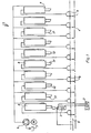
- the total chain lubrication designated 1 can be gem. 1 via a multi-way valve 2, whereupon an actuating device 3 (cf. FIG. 2) triggers the oil supply depending on the speed of the continuously rotating chain 4 via the drive sprocket 5.
- a hydraulic motor 6 then delivers lubricating oil from an oil tank 7 to the individual high-pressure pumps 8, which can be actuated in succession by a cam and deliver the desired amount of lubricant to the lubrication points of the chain 4 by means of the oil application nozzles 9, as will be explained in more detail below.
- the spray stroke is synchronized via the chain 4 to be lubricated or its chain wheel 5, which is connected to the chain lubrication 1 via toothed belts (not shown) and an angular gear 12.
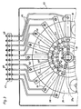
- the angular gear 12 has a shaft journal 13 on the output side with a wedged coupling half 14 which engages in the second coupling half 15 carried by the express coupling shaft 17.
- the two coupling halves 14, 15 form a claw coupling 16.
- Two wedges 18 secure on a coupling shaft 17 a cam carrier guide sleeve 19 which receives two control cams 23 which are adjustably mounted in it by means of bolts 22.
- a bearing 24 fixes and includes the guide sleeve 19, which in turn is located in a bearing flange 25, which is connected to the angular gear 12 via a centering plate 26, spacers 27, 28, a pump support plate 29 and a base plate 32.
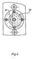
- a bearing 33 carries a driving sleeve 34 with a groove-like recess 35 into which the actuating device 3 engages by means of a driving bracket 36 (see FIG. 4) and the coupling shaft 17 for starting up the lubrication with the Shaft journal 13 connects or separates from it during the lubrication breaks.
- the drive cams 23 meet the run-up slopes 42 and convert the rotary movement into a linear movement for the pump pistons 43, so that each pump piston 43 moves in the direction of the pump head 44 and that in Pressure chamber 45 contains oil via the pipes 46 to the oil application nozzles 9.
- a nozzle holder 47 arranged in the lubrication area above the chain 4 secures the position of the pipes 46, which merge below the nozzle holder 47 into an oil distributor pipe 48 each with a halved pipe cross section, at the ends of which the oil application nozzles 9 are located.
- the nozzles 9 are aligned on the left and right of the chain exactly over the lubrication points 49 on a chain pin 52.
- An additional chain guide 53 supports the precise alignment of the chain 4 under the nozzles 9, just as the oil distributor pipes 9 can also be encapsulated by means of a protective plate 54.
- Each pump 8 has a spring-loaded check valve 57 and 58 in both the suction line 55 and the high-pressure line 56.
- the suction lines 55 receive oil from an oil distributor 62 via feed lines 59.
- the complete lubrication device 1, in particular its mechanically stressed parts, are together with the Oil distributor 62 housed in a housing 63 filled with oil.
- a sensor 64 queries the lubrication points 49 running via the chain wheel 5, which are forwarded to the pause counter 65 as counting pulses during the lubrication breaks. After counting down the number of lubrication points entered into the pause counter 65 to zero, the pause counter 65 releases the pulses for a lubrication counter 66 and at the same time puts the actuating device 3 into operation.
- the actuating device 3 connects the clutch shaft 17 to the shaft journal 13 of the angular gear 12, whereupon the torque removed from the drive sprocket 5 is immediately transmitted to the clutch shaft 17 and rotates together with the cam carrier guide sleeve 19 and the control cams 23 at the same speed as the chain.
- the control cams 23 successively meet the deflection cams 37, which in their starting position rest against the guide ring 39 with a collar 67 and thus consequently all take up the work cycle from the same position into which they also have a return spring 68 after the spray stroke has ended resets.
- the width and slope of the deflection cam 37 precisely defines the start and end of spraying, the control cam 23 moving the pump piston 43 toward the right in the direction of the pump head 44 while running on the run-up slope 42 and thereby the lubricating oil from the pressure chamber 45 to the Nozzles 9 promotes.
- the check valve 58 closes the high-pressure side 56 and prevents the lubricating oil from flowing in again.
- the return spring 68 returns the deflection cam 37 to its initial position, and the check valve 57 of the intake line 55 opens due to the resulting negative pressure, so that the pressure space 45 can be filled via the supply line 59 from the oil distributor 62 at the same time.
- the chain is lubricated by means of the cam control until the lubrication counter 66 has reached zero.
- the actuator 3 then disconnects the chain lubrication release mechanism, i.e. the actuating device 3 is acted upon and separates the coupling shaft from the shaft journal 13 by means of the driving bracket 36 which is latched into the recess 35 of the driving sleeve 34, so that the lubricating device is at rest.
- the trigger mechanism is out of operation (cf. FIG. 5)
- the hydraulic motor or the hydraulic pump 6 also no longer delivers lubricating oil.
- the lubrication cycle only starts again when the pause counter 65 has been counted down to zero and then releases the pulse again for the lubrication counter 66.
Landscapes
- Engineering & Computer Science (AREA)
- General Engineering & Computer Science (AREA)
- Mechanical Engineering (AREA)
- General Details Of Gearings (AREA)
- Lubrication Of Internal Combustion Engines (AREA)
- Devices For Conveying Motion By Means Of Endless Flexible Members (AREA)
- Lubricants (AREA)
Claims (12)
Priority Applications (1)
| Application Number | Priority Date | Filing Date | Title |
|---|---|---|---|
| AT84111889T ATE45129T1 (de) | 1983-11-18 | 1984-10-04 | Vorrichtung zum schmieren einer kette. |
Applications Claiming Priority (2)
| Application Number | Priority Date | Filing Date | Title |
|---|---|---|---|
| DE3341658 | 1983-11-18 | ||
| DE3341658A DE3341658C2 (de) | 1983-11-18 | 1983-11-18 | Vorrichtung zum Schmieren einer Kette |
Publications (3)
| Publication Number | Publication Date |
|---|---|
| EP0142687A2 EP0142687A2 (fr) | 1985-05-29 |
| EP0142687A3 EP0142687A3 (en) | 1986-05-14 |
| EP0142687B1 true EP0142687B1 (fr) | 1989-08-02 |
Family
ID=6214608
Family Applications (1)
| Application Number | Title | Priority Date | Filing Date |
|---|---|---|---|
| EP84111889A Expired EP0142687B1 (fr) | 1983-11-18 | 1984-10-04 | Appareil de lubrification de chaîne |
Country Status (8)
| Country | Link |
|---|---|
| US (1) | US4679659A (fr) |
| EP (1) | EP0142687B1 (fr) |
| JP (1) | JPS60125498A (fr) |
| AT (1) | ATE45129T1 (fr) |
| AU (1) | AU3517384A (fr) |
| CA (1) | CA1240276A (fr) |
| DE (1) | DE3341658C2 (fr) |
| ZA (1) | ZA848959B (fr) |
Families Citing this family (18)
| Publication number | Priority date | Publication date | Assignee | Title |
|---|---|---|---|---|
| US5186280A (en) * | 1991-05-03 | 1993-02-16 | Mattcheck Donald L | High temperature oven conveyor chain lubrication system |
| US5129481A (en) * | 1992-01-29 | 1992-07-14 | Pure-Chem Products Company, Inc. | Apparatus and method for lubricating conveyors |
| US5289899A (en) * | 1992-12-21 | 1994-03-01 | Pure-Chem Products Company, Inc. | Apparatus and method for lubricating conveyors |
| DE4406099C2 (de) * | 1994-02-25 | 2001-07-05 | Bielomatik Leuze & Co | Schmiervorrichtung zur Versorgung mobiler Schmierstellen |
| DE19503861C2 (de) * | 1995-02-07 | 1999-07-22 | Satzinger Gmbh & Co | Verfahren zum dosierten Schmieren eines Kettentriebes, insbesondere eines Motorrad-Kettentriebes |
| DE19529368C1 (de) * | 1995-08-10 | 1996-10-31 | Dolmar Gmbh | Vorrichtung mit Kraftstoffeinspritzung und Schmiermittelfördereinrichtung für Verbrennungsmotoren |
| JP3208325B2 (ja) * | 1996-06-18 | 2001-09-10 | 株式会社育良精機製作所 | 棒材供給機 |
| DE19739525A1 (de) * | 1997-09-09 | 1999-09-30 | Heinrich Abbrederis | Die Vorrichtung T.C.Reinigungskopf ermöglicht die Reinigung, Schmierung und Konservierung von Ketten im eingebauten und ausgebauten Zustand unter minimalen Platzverhältnissen |
| NL1011597C2 (nl) * | 1999-03-18 | 2000-09-19 | Haanschoten Josef Gijsbert | Smeerinrichting voor aandrijfketting. |
| US7314353B2 (en) * | 2004-10-08 | 2008-01-01 | Urschel Laboratories, Inc. | Pump assembly for transporting a cooling fluid |
| WO2006108178A2 (fr) * | 2005-04-07 | 2006-10-12 | Rodriguez, Damian | Systeme et procede de surveillance d'un broyeur a impact a arbre vertical |
| US7455170B2 (en) * | 2005-11-15 | 2008-11-25 | Xact Fluid Solutions Division Of Behnke Lubricants, Jax Usa | Conveyor chain lubrication system |
| DE102006020368A1 (de) * | 2006-02-09 | 2007-08-16 | Cfs Germany Gmbh | Verpackungsmaschine mit einer Kettenreinigung |
| US20080296093A1 (en) * | 2006-11-24 | 2008-12-04 | Schippers John F | Lubricating Switch |
| MX2007015324A (es) * | 2006-12-18 | 2009-02-20 | Inventio Ag | Sistema y procedimiento para engrasar una instalacion de transporte. |
| EP2966013B1 (fr) * | 2014-07-09 | 2019-09-04 | SKF Lubrication Systems France | Injecteur télescopique de lubrification, particulièrement pour un système d'injection de graisse |
| CA2961618C (fr) * | 2016-03-22 | 2021-12-21 | Gjr Meyer Service Inc. | Collecteur de lubrification |
| CN105805523B (zh) * | 2016-06-02 | 2018-04-06 | 厦门烟草工业有限责任公司 | 自动润滑装置及自动润滑方法 |
Family Cites Families (18)
| Publication number | Priority date | Publication date | Assignee | Title |
|---|---|---|---|---|
| GB592386A (en) * | 1945-05-18 | 1947-09-16 | Tecalemit Ltd | Improvements relating to reciprocating pumps, particularly for central lubrication systems |
| US1900745A (en) * | 1929-12-26 | 1933-03-07 | Sukete Invest Company | Progressive distributing lubricator |
| US1979863A (en) * | 1931-05-19 | 1934-11-06 | Eben H Carruthers | Pump |
| US2022620A (en) * | 1933-06-20 | 1935-11-26 | Texas Co | Lubricating mechanism |
| US2561785A (en) * | 1945-06-15 | 1951-07-24 | Ernest W Davis | Lubricating apparatus |
| DE837793C (de) * | 1950-07-06 | 1952-05-02 | Robert Karl Otto Vogelgesang | Schmiermittelpumpe mit einer Mehrzahl je fuer sich austauschbarer und um eine gemeinsame senkrechte mittlere Achse angeordneter Pumpenelemente |
| DE1697671U (de) * | 1955-02-21 | 1955-05-05 | Helios App Wetzel & Schlosshau | Schmiertaktgeber. |
| DE1099282B (de) * | 1956-11-08 | 1961-02-09 | Clarke Chapman Ltd | Schmiervorrichtung fuer Gelenkketten |
| US3073415A (en) * | 1960-06-08 | 1963-01-15 | Olsen Mfg Company | Conveyor lubricating apparatus |
| GB1141371A (en) * | 1966-08-12 | 1969-01-29 | Cyril Douglas Lister | Improvements in or relating to spray lubricating devices |
| US3463268A (en) * | 1966-11-14 | 1969-08-26 | Owens Corning Fiberglass Corp | Self-actuated oiling system |
| DE1984854U (de) * | 1967-09-29 | 1968-05-02 | Hans Biel Fa | Vorrichtung zum schmieren von laufenden ketten. |
| JPS474370Y1 (fr) * | 1968-10-11 | 1972-02-15 | ||
| US3561565A (en) * | 1969-09-15 | 1971-02-09 | Dennis Frederick Woor | Pulse-actuated lubrication system |
| US4009764A (en) * | 1974-05-22 | 1977-03-01 | Hafner Henry F | Lubricating apparatus for conveyor chains |
| US4085821A (en) * | 1976-09-07 | 1978-04-25 | Madison-Kipp Corporation | Lubrication system |
| GB2021703B (en) * | 1978-05-25 | 1983-02-09 | Madison Kipp Corp | Electrical lubricating apparatus |
| US4401188A (en) * | 1981-04-06 | 1983-08-30 | C. L. Frost & Son, Inc. | Chain spraying apparatus |
-
1983
- 1983-11-18 DE DE3341658A patent/DE3341658C2/de not_active Expired
-
1984
- 1984-10-04 AT AT84111889T patent/ATE45129T1/de not_active IP Right Cessation
- 1984-10-04 EP EP84111889A patent/EP0142687B1/fr not_active Expired
- 1984-11-07 AU AU35173/84A patent/AU3517384A/en not_active Abandoned
- 1984-11-13 CA CA000467626A patent/CA1240276A/fr not_active Expired
- 1984-11-16 ZA ZA848959A patent/ZA848959B/xx unknown
- 1984-11-16 JP JP59242162A patent/JPS60125498A/ja active Pending
-
1986
- 1986-06-18 US US06/875,503 patent/US4679659A/en not_active Expired - Lifetime
Non-Patent Citations (1)
| Title |
|---|
| J. FAISANDIER ET AL: Mécanismes hydrauliques, Paris 1980, Seiten 56-66 * |
Also Published As
| Publication number | Publication date |
|---|---|
| ATE45129T1 (de) | 1989-08-15 |
| DE3341658A1 (de) | 1985-05-30 |
| JPS60125498A (ja) | 1985-07-04 |
| DE3341658C2 (de) | 1986-07-10 |
| AU3517384A (en) | 1985-05-23 |
| EP0142687A2 (fr) | 1985-05-29 |
| US4679659A (en) | 1987-07-14 |
| EP0142687A3 (en) | 1986-05-14 |
| CA1240276A (fr) | 1988-08-09 |
| ZA848959B (en) | 1985-07-31 |
Similar Documents
| Publication | Publication Date | Title |
|---|---|---|
| EP0142687B1 (fr) | Appareil de lubrification de chaîne | |
| DE69220549T2 (de) | Vorrichtung zum Injizieren von Lake | |
| EP1186826B1 (fr) | Lubrificateur pour lubrification de points mobiles | |
| EP1656520B1 (fr) | Appareil de lubrification et dispositif de lubrification presentant un tel appareil | |
| CH647699A5 (de) | Antriebseinrichtung fuer biegeschlitten von stanz-biegeautomaten. | |
| EP0502823B1 (fr) | Dispositif de lubrification par intermittence à l'aide d'un brouillard de lubrificant | |
| DE3034284C2 (fr) | ||
| DE3312589C2 (de) | Vorrichtung zum Schmieren von laufenden Ketten | |
| DE560073C (de) | Brennstoffpumpe | |
| DE947040C (de) | Hydraulisch angetriebene Kolbenpumpe zur Foerderung von dickfluessigen, breiigen Massen, z. B. Beton | |
| DE2514022C3 (de) | Vorrichtung zum Schmieren der Gelenkverbindungen von endlosen Förderketten | |
| DE2265037B2 (de) | Vorrichtung zum Schmieren der Kette eines Förderers, insbesondere eines Kreisförderers | |
| DE3430040A1 (de) | Zentralschmieranlage fuer wandernde schmierstellen | |
| EP1538336B1 (fr) | Pompe de dosage | |
| DE582111C (de) | Abteilvorrichtung fuer Wurstfuellmaschinen | |
| DE475036C (de) | Hochdruckbrennstoffpumpenanlage fuer direkte Brennstoffeinspritzung in die Zylinder von schnellaufenden Motoren | |
| DE19834599C2 (de) | Flüssigkeits-Fördersystem | |
| DE874697C (de) | Vorschubvorrichtung fuer Naehmaschinen | |
| CH404326A (de) | Antriebsvorrichtung mit gradlinigen, nach Länge und Geschwindigkeit veränderbaren Hubbewegungen | |
| DE19701248A1 (de) | Vorrichtung zum Steuern eines Zylinders | |
| DE643796C (de) | Vorrichtung zum Abbremsen der aus einer Strangzigarettenmaschine austretenden Zigaretten | |
| DE398683C (de) | Vorrichtung zum Schmieren des Kardangelenkes von Kraftfahrzeugen | |
| DE10196445T5 (de) | Flüssigkeitspumpe und Dosiervorrichtung | |
| DE3617396C2 (fr) | ||
| DE1503340A1 (de) | Antrieb einer langsamen Welle |
Legal Events
| Date | Code | Title | Description |
|---|---|---|---|
| PUAI | Public reference made under article 153(3) epc to a published international application that has entered the european phase |
Free format text: ORIGINAL CODE: 0009012 |
|
| AK | Designated contracting states |
Designated state(s): AT BE CH FR GB IT LI LU NL SE |
|
| PUAL | Search report despatched |
Free format text: ORIGINAL CODE: 0009013 |
|
| AK | Designated contracting states |
Kind code of ref document: A3 Designated state(s): AT BE CH FR GB IT LI LU NL SE |
|
| 17P | Request for examination filed |
Effective date: 19861008 |
|
| 17Q | First examination report despatched |
Effective date: 19870714 |
|
| ITF | It: translation for a ep patent filed | ||
| GRAA | (expected) grant |
Free format text: ORIGINAL CODE: 0009210 |
|
| AK | Designated contracting states |
Kind code of ref document: B1 Designated state(s): AT BE CH FR GB IT LI LU NL SE |
|
| REF | Corresponds to: |
Ref document number: 45129 Country of ref document: AT Date of ref document: 19890815 Kind code of ref document: T |
|
| ET | Fr: translation filed | ||
| GBT | Gb: translation of ep patent filed (gb section 77(6)(a)/1977) | ||
| PLBE | No opposition filed within time limit |
Free format text: ORIGINAL CODE: 0009261 |
|
| STAA | Information on the status of an ep patent application or granted ep patent |
Free format text: STATUS: NO OPPOSITION FILED WITHIN TIME LIMIT |
|
| 26N | No opposition filed | ||
| PGFP | Annual fee paid to national office [announced via postgrant information from national office to epo] |
Ref country code: GB Payment date: 19910919 Year of fee payment: 8 |
|
| PGFP | Annual fee paid to national office [announced via postgrant information from national office to epo] |
Ref country code: FR Payment date: 19911017 Year of fee payment: 8 |
|
| PGFP | Annual fee paid to national office [announced via postgrant information from national office to epo] |
Ref country code: SE Payment date: 19911023 Year of fee payment: 8 |
|
| PGFP | Annual fee paid to national office [announced via postgrant information from national office to epo] |
Ref country code: LU Payment date: 19911025 Year of fee payment: 8 Ref country code: AT Payment date: 19911025 Year of fee payment: 8 |
|
| ITTA | It: last paid annual fee | ||
| PGFP | Annual fee paid to national office [announced via postgrant information from national office to epo] |
Ref country code: NL Payment date: 19911031 Year of fee payment: 8 |
|
| PGFP | Annual fee paid to national office [announced via postgrant information from national office to epo] |
Ref country code: CH Payment date: 19911118 Year of fee payment: 8 |
|
| PGFP | Annual fee paid to national office [announced via postgrant information from national office to epo] |
Ref country code: BE Payment date: 19911127 Year of fee payment: 8 |
|
| EPTA | Lu: last paid annual fee | ||
| PG25 | Lapsed in a contracting state [announced via postgrant information from national office to epo] |
Ref country code: LU Free format text: LAPSE BECAUSE OF NON-PAYMENT OF DUE FEES Effective date: 19921004 Ref country code: GB Effective date: 19921004 Ref country code: AT Effective date: 19921004 |
|
| PG25 | Lapsed in a contracting state [announced via postgrant information from national office to epo] |
Ref country code: SE Effective date: 19921005 |
|
| PG25 | Lapsed in a contracting state [announced via postgrant information from national office to epo] |
Ref country code: LI Effective date: 19921031 Ref country code: CH Effective date: 19921031 Ref country code: BE Effective date: 19921031 |
|
| BERE | Be: lapsed |
Owner name: GERROKAISER DOSENWERK G.M.B.H. & CO. K.G. Effective date: 19921031 |
|
| PG25 | Lapsed in a contracting state [announced via postgrant information from national office to epo] |
Ref country code: NL Effective date: 19930501 |
|
| GBPC | Gb: european patent ceased through non-payment of renewal fee |
Effective date: 19921004 |
|
| NLV4 | Nl: lapsed or anulled due to non-payment of the annual fee | ||
| PG25 | Lapsed in a contracting state [announced via postgrant information from national office to epo] |
Ref country code: FR Effective date: 19930630 |
|
| REG | Reference to a national code |
Ref country code: CH Ref legal event code: PL |
|
| REG | Reference to a national code |
Ref country code: FR Ref legal event code: ST |
|
| EUG | Se: european patent has lapsed |
Ref document number: 84111889.6 Effective date: 19930510 |