EP0142736B1 - Appareil d'infusion sous pression avec une seringue jetable - Google Patents
Appareil d'infusion sous pression avec une seringue jetable Download PDFInfo
- Publication number
- EP0142736B1 EP0142736B1 EP84112824A EP84112824A EP0142736B1 EP 0142736 B1 EP0142736 B1 EP 0142736B1 EP 84112824 A EP84112824 A EP 84112824A EP 84112824 A EP84112824 A EP 84112824A EP 0142736 B1 EP0142736 B1 EP 0142736B1
- Authority
- EP
- European Patent Office
- Prior art keywords
- cylinder
- pressure
- wall portion
- deformable wall
- disposable syringe
- Prior art date
- Legal status (The legal status is an assumption and is not a legal conclusion. Google has not performed a legal analysis and makes no representation as to the accuracy of the status listed.)
- Expired
Links
Images
Classifications
-
- A—HUMAN NECESSITIES
- A61—MEDICAL OR VETERINARY SCIENCE; HYGIENE
- A61M—DEVICES FOR INTRODUCING MEDIA INTO, OR ONTO, THE BODY; DEVICES FOR TRANSDUCING BODY MEDIA OR FOR TAKING MEDIA FROM THE BODY; DEVICES FOR PRODUCING OR ENDING SLEEP OR STUPOR
- A61M5/00—Devices for bringing media into the body in a subcutaneous, intra-vascular or intramuscular way; Accessories therefor, e.g. filling or cleaning devices, arm rests
- A61M5/14—Infusion devices, e.g. infusing by gravity; Blood infusion; Accessories therefor
- A61M5/142—Pressure infusion, e.g. using pumps
- A61M5/145—Pressure infusion, e.g. using pumps using pressurised reservoirs, e.g. by means of pistons
- A61M5/1452—Pressure infusion, e.g. using pumps using pressurised reservoirs, e.g. by means of pistons pressurised by means of pistons
- A61M5/1456—Pressure infusion, e.g. using pumps using pressurised reservoirs, e.g. by means of pistons pressurised by means of pistons with a replaceable reservoir comprising a piston rod to be moved into the reservoir, e.g. the piston rod is part of the removable reservoir
-
- A—HUMAN NECESSITIES
- A61—MEDICAL OR VETERINARY SCIENCE; HYGIENE
- A61M—DEVICES FOR INTRODUCING MEDIA INTO, OR ONTO, THE BODY; DEVICES FOR TRANSDUCING BODY MEDIA OR FOR TAKING MEDIA FROM THE BODY; DEVICES FOR PRODUCING OR ENDING SLEEP OR STUPOR
- A61M5/00—Devices for bringing media into the body in a subcutaneous, intra-vascular or intramuscular way; Accessories therefor, e.g. filling or cleaning devices, arm rests
- A61M5/14—Infusion devices, e.g. infusing by gravity; Blood infusion; Accessories therefor
- A61M5/168—Means for controlling media flow to the body or for metering media to the body, e.g. drip meters, counters
- A61M5/16831—Monitoring, detecting, signalling or eliminating infusion flow anomalies
- A61M5/16854—Monitoring, detecting, signalling or eliminating infusion flow anomalies by monitoring line pressure
-
- Y—GENERAL TAGGING OF NEW TECHNOLOGICAL DEVELOPMENTS; GENERAL TAGGING OF CROSS-SECTIONAL TECHNOLOGIES SPANNING OVER SEVERAL SECTIONS OF THE IPC; TECHNICAL SUBJECTS COVERED BY FORMER USPC CROSS-REFERENCE ART COLLECTIONS [XRACs] AND DIGESTS
- Y10—TECHNICAL SUBJECTS COVERED BY FORMER USPC
- Y10S—TECHNICAL SUBJECTS COVERED BY FORMER USPC CROSS-REFERENCE ART COLLECTIONS [XRACs] AND DIGESTS
- Y10S128/00—Surgery
- Y10S128/01—Motorized syringe
Definitions
- the invention relates to a pressure infusion apparatus with a disposable syringe which has a cylinder in which a piston which is displaceable by the pressure infusion apparatus is arranged.
- Pressure infusion apparatuses (DE-A-3 150 623) for medical applications are known in which a syringe is slowly and continuously squeezed out to carry out continuous infusions.
- the syringe is attached with its cylinder to a holder of the pressure infusion apparatus, while a slide pushes the piston rod towards the holder at a defined speed, so that the infusion solution contained in the syringe is pushed out of the cylinder continuously and at a predetermined selectable rate.
- an alarm signal must be generated that indicates to the clinic staff that the infusion is disturbed or that the cylinder has become empty and may need to be replaced with a new cylinder.
- the alarm signal is generated in that the holder to which the cylinder is attached can carry out a displacement movement and is biased by a spring in the direction of the slide.
- the invention has for its object to provide a disposable syringe of the type mentioned, which makes it possible to determine an overload case with little effort due to the pressure or force conditions prevailing in the cylinder.
- a deformable wall part is provided on the cylinder, which is deformable by the liquid pressure or by direct contact with the piston and actuates the position sensor when deformed.
- This has the advantage that the syringe can be fixed by a holder, which in turn is firmly connected to the housing of the pressure infusion apparatus and does not have to be attached in a displaceable manner.
- the position sensor is also firmly connected to the housing of the pressure infusion apparatus, it being possible, of course, to provide an adjustment option for changing the position of the position sensor.
- a pressure in the interior of the cylinder actuates the position sensor, which is preferably located at the end of the cylinder on the outlet side, through the deformable wall part.
- the deformable wall part can also be moved by direct contact with the piston in order to actuate the position sensor.
- the deformable wall part is the outlet-side end wall (cylinder face) of the cylinder.
- the cylinder face is particularly suitable as a deformable wall part, since it is on the one hand at the front (exhaust-side) cylinder end and, on the other hand, if it is deformed, the inside width of the cylinder is not changed and the seal against the piston is not deteriorated.
- the deformable wall part can also be arranged in the peripheral wall of the cylinder.
- the deformable wall part to a certain extent has the function of a bladder, which can be directed into the interior of the cylinder and is deformed outwards when the liquid pressure is too great in order to actuate the position sensor.
- a bladder which can be directed into the interior of the cylinder and is deformed outwards when the liquid pressure is too great in order to actuate the position sensor.
- Such an outward deformation of the bladder also occurs when the piston reaches the bladder and presses it outward as it moves forward.
- Any other flexible cross-sectional constriction of the cylinder is also suitable for this. If the sensor is only to respond to the fluid pressure, but not to the position of the piston, the flexible wall part can have any shape, it only being necessary to ensure that it expands outward when the fluid pressure is excessive.
- the position sensor is a switch that is actuated by the deformable wall part.
- a position sensor which delivers an output signal proportional to the position of the deformable wall part. In this way, a pre-alarm can be given or the pressure or the position of the piston can be specified, so that the clinic staff can monitor the size of the relevant value even before the acute alarm condition.
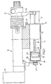
- the pressure infusion apparatus shown has an elongated tubular housing 10, on the underside of which a first holder 11 is fixedly attached.
- a slide 12 is guided, which protrudes from the free end of the housing and carries a downwardly projecting second holder 13.
- the linear movement of the slide 12 is driven by a motor 14 attached to the housing 10.
- the holder 11 has a lateral opening into which the cylinder 19 of the syringe 16 is inserted laterally.
- a flange 17 at the rear end of the cylinder 19 is supported on the rear of the holder 11.
- the flange 17 is encompassed by a shoulder 27 of the holder 11, so that the cylinder 19 is fixed in the direction of its longitudinal axis.
- the syringe 16 consists of a cylinder 19 and a piston 20 which is displaceable in the cylinder.
- a projecting flange 18 is attached to the neck 15 of the cylinder 19.
- the piston 20 has a piston rod 21 which projects from the rear end of the cylinder 19 and is profiled at its outer end in such a way that it can be fixed on the holder 13.
- a hose (not shown), which leads from the syringe 16 to the patient, is connected to a connecting piece 22 which is molded onto the neck 15.
- the plunger 20 is in a position near the rear cylinder end at the start of the infusion.
- the motor 14 drives the slide 12 in such a way that the piston 20 is slowly advanced in the cylinder 19 and in doing so pushes out the syringe content through the nozzle 22.
- the cylinder face, i.e. the outlet-side end wall of the cylinder 19 is designed as a deformable wall part 23.
- This wall part 23 can, for example, have a smaller wall thickness than the other wall parts of the cylinder.
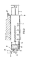
- a position sensor 25 is fastened to the housing 10 or holder 11 and engages around the area of the neck 15 lying in front of the flange 18 with a fork-shaped stylus 26. If the flexible wall part 23 is deformed in the manner shown in FIG. 2, either by too high a liquid pressure occurring inside the cylinder 19 or by pushing this wall part 23 forward by contact with the piston 20, the stylus 26 becomes more flexible Wall 23 and the advanced neck 15 taken and moved towards the outlet end of the syringe. This enables a switching operation to be carried out.
- the wall 23 with the neck 15 moves in the axial direction of the syringe, i.e. the neck 15 is advanced by an overpressure prevailing in the cylinder 19 (to the left in the drawing), as shown in FIG. 2.
- the flexible wall 23 which in the rest state (FIG. 1) has the shape of a flat radial disk, deforms in the shape of a truncated cone (FIG. 2) and displaces the neck 1 and the stylus 26.
- the deformation can occur either due to a high fluid pressure in the cylinder or by mechanical shaping using the conical syringe of the piston 20.
- the position sensor 25 can be designed such that it generates an electrical signal, the magnitude of which is proportional to the position of the stylus 26.
- the entire syringe, which is designed as a disposable syringe, is made of plastic, the deformable wall 23 being made thinner-walled than the other wall parts.
Landscapes
- Health & Medical Sciences (AREA)
- Vascular Medicine (AREA)
- Engineering & Computer Science (AREA)
- Anesthesiology (AREA)
- Biomedical Technology (AREA)
- Heart & Thoracic Surgery (AREA)
- Hematology (AREA)
- Life Sciences & Earth Sciences (AREA)
- Animal Behavior & Ethology (AREA)
- General Health & Medical Sciences (AREA)
- Public Health (AREA)
- Veterinary Medicine (AREA)
- Infusion, Injection, And Reservoir Apparatuses (AREA)
Claims (6)
Priority Applications (1)
| Application Number | Priority Date | Filing Date | Title |
|---|---|---|---|
| AT84112824T ATE27107T1 (de) | 1983-11-09 | 1984-10-24 | Druckinfusionsapparate mit einer einmalspritze. |
Applications Claiming Priority (2)
| Application Number | Priority Date | Filing Date | Title |
|---|---|---|---|
| DE3340511A DE3340511C1 (de) | 1983-11-09 | 1983-11-09 | Einmalspritze fuer Druckinfusionsapparate |
| DE3340511 | 1983-11-09 |
Publications (2)
| Publication Number | Publication Date |
|---|---|
| EP0142736A1 EP0142736A1 (fr) | 1985-05-29 |
| EP0142736B1 true EP0142736B1 (fr) | 1987-05-13 |
Family
ID=6213868
Family Applications (1)
| Application Number | Title | Priority Date | Filing Date |
|---|---|---|---|
| EP84112824A Expired EP0142736B1 (fr) | 1983-11-09 | 1984-10-24 | Appareil d'infusion sous pression avec une seringue jetable |
Country Status (5)
| Country | Link |
|---|---|
| US (1) | US4624658A (fr) |
| EP (1) | EP0142736B1 (fr) |
| JP (1) | JPS60122570A (fr) |
| AT (1) | ATE27107T1 (fr) |
| DE (2) | DE3340511C1 (fr) |
Cited By (3)
| Publication number | Priority date | Publication date | Assignee | Title |
|---|---|---|---|---|
| EP0314880A3 (en) * | 1987-11-04 | 1989-09-13 | B. Braun Melsungen Ag | Pressure infusion apparatus |
| US5259732A (en) * | 1992-04-29 | 1993-11-09 | Becton, Dickinson And Company | Syringe pump with syringe barrel position detector |
| WO2002087665A1 (fr) | 2001-04-26 | 2002-11-07 | Groening Ruediger | Pompe pour administrer des medicaments de façon dosee et regulee dans le temps |
Families Citing this family (18)
| Publication number | Priority date | Publication date | Assignee | Title |
|---|---|---|---|---|
| US4769009A (en) * | 1986-10-10 | 1988-09-06 | Cobe Laboratories, Inc. | Apparatus for displacing a piston in a chamber having a torque resistor |
| DE3741802C1 (de) * | 1987-12-10 | 1988-11-24 | Braun Melsungen Ag | Verfahren zur UEberwachung des Betriebs einer Infusionsspritzenpumpe |
| FR2625102B1 (fr) * | 1987-12-24 | 1994-06-10 | Godefroy Alain | Perfectionnement aux pousse-seringues universels |
| US4978335A (en) * | 1989-09-29 | 1990-12-18 | Medex, Inc. | Infusion pump with bar code input to computer |
| US5295967A (en) * | 1992-09-23 | 1994-03-22 | Becton, Dickinson And Company | Syringe pump having continuous pressure monitoring and display |
| USD370974S (en) | 1995-01-27 | 1996-06-18 | Hamilton Company | Manual dispensing aid for a syringe |
| US5704912A (en) * | 1995-03-17 | 1998-01-06 | Advanced Cardiovascular Systems, Inc. | Syringe assembly mounting system for inflation control system |
| US6221045B1 (en) | 1995-04-20 | 2001-04-24 | Acist Medical Systems, Inc. | Angiographic injector system with automatic high/low pressure switching |
| KR100469207B1 (ko) | 1995-10-20 | 2005-03-16 | 화이자 헬스 에이비 | 전자식주입조정장치 |
| US6171276B1 (en) | 1997-08-06 | 2001-01-09 | Pharmacia & Upjohn Ab | Automated delivery device and method for its operation |
| CH692543A5 (de) | 1997-09-25 | 2002-07-31 | Disetronic Licensing Ag | Abgabevorrichtung mit Signalgeber. |
| US6086569A (en) * | 1999-05-04 | 2000-07-11 | Schweizer; Kenneth M. | Hypodermic syringe |
| US20030105433A1 (en) * | 2001-11-30 | 2003-06-05 | Ruben Philip H. | Disposable syringe and cartridge with pneumatic chamber |
| US6780170B2 (en) * | 2002-05-15 | 2004-08-24 | Liebel-Flarsheim Company | Hydraulic remote for a medical fluid injector |
| US8805700B2 (en) * | 2006-03-14 | 2014-08-12 | Nemoto Kyorindo Co., Ltd. | Medical image system |
| US8696626B2 (en) * | 2008-07-30 | 2014-04-15 | Claudia F. E. Kirsch | Debubbler |
| CN107440814A (zh) * | 2017-07-31 | 2017-12-08 | 山东中医药大学 | 一种可调式精准连续注射器及其使用方法 |
| CN113453738B (zh) * | 2019-02-08 | 2023-11-21 | 追踪注射器有限责任公司 | 针传感器组件及其使用方法 |
Family Cites Families (9)
| Publication number | Priority date | Publication date | Assignee | Title |
|---|---|---|---|---|
| DE372943C (de) * | 1923-04-06 | Ver Bornkesselwerke M B H | Spritze mit Vorratsbehaelter | |
| US2742901A (en) * | 1951-01-23 | 1956-04-24 | Krauthamer Sigfrid | Apparatus for injection of fluid under controlled pressure conditions |
| US3884228A (en) * | 1974-02-26 | 1975-05-20 | Lynkeus Corp | Intravenous feeding system |
| US4126132A (en) * | 1975-07-28 | 1978-11-21 | Andros Incorporated | Intravenous and intra arterial delivery system |
| US4030497A (en) * | 1975-11-03 | 1977-06-21 | The Kendall Company | Syringe assembly |
| US4204538A (en) * | 1978-06-07 | 1980-05-27 | Imed Corporation | Cassette for intravenous controller |
| DE3150623C2 (de) * | 1981-12-21 | 1983-12-01 | B. Braun Melsungen Ag, 3508 Melsungen | Druckinfusionsapparat für medizinische Anwendungen |
| DE8137235U1 (de) * | 1981-12-21 | 1982-05-19 | B. Braun Melsungen Ag, 3508 Melsungen | Druckinfussionsapparat fuer medizinische anwendungen |
| US4435173A (en) * | 1982-03-05 | 1984-03-06 | Delta Medical Industries | Variable rate syringe pump for insulin delivery |
-
1983
- 1983-11-09 DE DE3340511A patent/DE3340511C1/de not_active Expired
-
1984
- 1984-10-24 EP EP84112824A patent/EP0142736B1/fr not_active Expired
- 1984-10-24 AT AT84112824T patent/ATE27107T1/de not_active IP Right Cessation
- 1984-10-24 DE DE8484112824T patent/DE3463614D1/de not_active Expired
- 1984-11-05 US US06/667,997 patent/US4624658A/en not_active Expired - Fee Related
- 1984-11-09 JP JP59237410A patent/JPS60122570A/ja active Pending
Cited By (3)
| Publication number | Priority date | Publication date | Assignee | Title |
|---|---|---|---|---|
| EP0314880A3 (en) * | 1987-11-04 | 1989-09-13 | B. Braun Melsungen Ag | Pressure infusion apparatus |
| US5259732A (en) * | 1992-04-29 | 1993-11-09 | Becton, Dickinson And Company | Syringe pump with syringe barrel position detector |
| WO2002087665A1 (fr) | 2001-04-26 | 2002-11-07 | Groening Ruediger | Pompe pour administrer des medicaments de façon dosee et regulee dans le temps |
Also Published As
| Publication number | Publication date |
|---|---|
| EP0142736A1 (fr) | 1985-05-29 |
| US4624658A (en) | 1986-11-25 |
| DE3340511C1 (de) | 1985-02-14 |
| DE3463614D1 (en) | 1987-06-19 |
| ATE27107T1 (de) | 1987-05-15 |
| JPS60122570A (ja) | 1985-07-01 |
Similar Documents
| Publication | Publication Date | Title |
|---|---|---|
| DE3340511C1 (de) | Einmalspritze fuer Druckinfusionsapparate | |
| DE3731242C2 (fr) | ||
| EP0581788B1 (fr) | Dispositif d'injection | |
| DE69231037T2 (de) | Spritzdrucksteuerungsvorrichtung | |
| DE69430578T2 (de) | Fördersystem zur geregelten infusion einer flüssigkeit | |
| EP0078899B1 (fr) | Seringue destinée à l'injection consécutive de deux fluides dans les vaisseaux sanguins de corps vivants | |
| DE69016982T2 (de) | Tragbares Medikamentenabgabegerät mit einer einen konischen Zylinder aufweisenden Pumpe. | |
| DE3733774A1 (de) | Fluessigkeitsauftrageinrichtung fuer schreibgeraete, kosmetische geraete und dergleichen | |
| DE10326306A1 (de) | Spritze, insbesondere für veterinärmedizinische Anwendungen | |
| DE3737331C1 (de) | Druckinfusionsapparat | |
| EP0082251A1 (fr) | Seringue pour deux fluides | |
| EP3355963B1 (fr) | Dispositif d'injection | |
| DE202007018843U1 (de) | Positionserfassungsvorrichtung zur Erfassung von mindestens zwei Positionen | |
| DE2347500A1 (de) | Injektionsspritze | |
| DE1653402B2 (de) | Auslaßventilanordnung | |
| DE3325622A1 (de) | Injektionsspritze | |
| DE2854647A1 (de) | Verfahren und vorrichtung zum abmessen und abgeben einer vorherbestimmten fluessigkeitsmenge | |
| DE2942801A1 (de) | Regler fuer eine fluessigkeits-dosiervorrichtung | |
| DE3200651A1 (de) | Kraftuebertragungs- und anzeigevorrichtung an durch fingerdruck betaetigten apparaten | |
| EP0319648B1 (fr) | Système pour surveiller le fonctionnement d'une pompe pour seringue d'infusion | |
| EP0090207A2 (fr) | Appareil pour le dosage sans contact de liquides | |
| DE69003528T2 (de) | Spritze zum waschen von zahnwurzelkanälen. | |
| EP0445387B1 (fr) | Pompe linéaire à tuyau | |
| EP1711216B1 (fr) | Seringue pour anesthesie | |
| WO2008106810A1 (fr) | Détection hydraulique d'une occlusion dans un appareil médical d'administration |
Legal Events
| Date | Code | Title | Description |
|---|---|---|---|
| PUAI | Public reference made under article 153(3) epc to a published international application that has entered the european phase |
Free format text: ORIGINAL CODE: 0009012 |
|
| AK | Designated contracting states |
Designated state(s): AT BE CH DE FR GB IT LI LU NL SE |
|
| 17P | Request for examination filed |
Effective date: 19850705 |
|
| 17Q | First examination report despatched |
Effective date: 19860507 |
|
| GRAA | (expected) grant |
Free format text: ORIGINAL CODE: 0009210 |
|
| AK | Designated contracting states |
Kind code of ref document: B1 Designated state(s): AT BE CH DE FR GB IT LI LU NL SE |
|
| REF | Corresponds to: |
Ref document number: 27107 Country of ref document: AT Date of ref document: 19870515 Kind code of ref document: T |
|
| ITF | It: translation for a ep patent filed | ||
| REF | Corresponds to: |
Ref document number: 3463614 Country of ref document: DE Date of ref document: 19870619 |
|
| ET | Fr: translation filed | ||
| PG25 | Lapsed in a contracting state [announced via postgrant information from national office to epo] |
Ref country code: LU Free format text: LAPSE BECAUSE OF NON-PAYMENT OF DUE FEES Effective date: 19871031 |
|
| PGFP | Annual fee paid to national office [announced via postgrant information from national office to epo] |
Ref country code: NL Payment date: 19871031 Year of fee payment: 4 |
|
| PLBE | No opposition filed within time limit |
Free format text: ORIGINAL CODE: 0009261 |
|
| STAA | Information on the status of an ep patent application or granted ep patent |
Free format text: STATUS: NO OPPOSITION FILED WITHIN TIME LIMIT |
|
| 26N | No opposition filed | ||
| REG | Reference to a national code |
Ref country code: CH Ref legal event code: PUE Owner name: B. BRAUN-SSC AG |
|
| PG25 | Lapsed in a contracting state [announced via postgrant information from national office to epo] |
Ref country code: GB Effective date: 19881024 Ref country code: AT Effective date: 19881024 |
|
| PG25 | Lapsed in a contracting state [announced via postgrant information from national office to epo] |
Ref country code: SE Effective date: 19881025 |
|
| PG25 | Lapsed in a contracting state [announced via postgrant information from national office to epo] |
Ref country code: LI Effective date: 19881031 Ref country code: CH Effective date: 19881031 Ref country code: BE Effective date: 19881031 |
|
| NLS | Nl: assignments of ep-patents |
Owner name: B. BRAUN-SSC AG TE EMMENBRUECKE, ZWITSERLAND. |
|
| BERE | Be: lapsed |
Owner name: INTERMEDICAT G.M.B.H. Effective date: 19881031 |
|
| PG25 | Lapsed in a contracting state [announced via postgrant information from national office to epo] |
Ref country code: NL Effective date: 19890501 |
|
| NLV4 | Nl: lapsed or anulled due to non-payment of the annual fee | ||
| PG25 | Lapsed in a contracting state [announced via postgrant information from national office to epo] |
Ref country code: FR Free format text: LAPSE BECAUSE OF NON-PAYMENT OF DUE FEES Effective date: 19890630 |
|
| REG | Reference to a national code |
Ref country code: CH Ref legal event code: PL |
|
| PG25 | Lapsed in a contracting state [announced via postgrant information from national office to epo] |
Ref country code: DE Effective date: 19890701 |
|
| GBPC | Gb: european patent ceased through non-payment of renewal fee | ||
| REG | Reference to a national code |
Ref country code: FR Ref legal event code: ST |
|
| EUG | Se: european patent has lapsed |
Ref document number: 84112824.2 Effective date: 19890621 |