EP0142774A2 - Vorrichtung zur Lichtablenkung - Google Patents
Vorrichtung zur Lichtablenkung Download PDFInfo
- Publication number
- EP0142774A2 EP0142774A2 EP84113379A EP84113379A EP0142774A2 EP 0142774 A2 EP0142774 A2 EP 0142774A2 EP 84113379 A EP84113379 A EP 84113379A EP 84113379 A EP84113379 A EP 84113379A EP 0142774 A2 EP0142774 A2 EP 0142774A2
- Authority
- EP
- European Patent Office
- Prior art keywords
- optical conductor
- conductor rod
- hole
- optical
- rod
- Prior art date
- Legal status (The legal status is an assumption and is not a legal conclusion. Google has not performed a legal analysis and makes no representation as to the accuracy of the status listed.)
- Withdrawn
Links
Images

Classifications
-
- G—PHYSICS
- G02—OPTICS
- G02B—OPTICAL ELEMENTS, SYSTEMS OR APPARATUS
- G02B6/00—Light guides; Structural details of arrangements comprising light guides and other optical elements, e.g. couplings
- G02B6/24—Coupling light guides
- G02B6/26—Optical coupling means
- G02B6/35—Optical coupling means having switching means
- G02B6/3538—Optical coupling means having switching means based on displacement or deformation of a liquid
-
- F—MECHANICAL ENGINEERING; LIGHTING; HEATING; WEAPONS; BLASTING
- F21—LIGHTING
- F21S—NON-PORTABLE LIGHTING DEVICES; SYSTEMS THEREOF; VEHICLE LIGHTING DEVICES SPECIALLY ADAPTED FOR VEHICLE EXTERIORS
- F21S6/00—Lighting devices intended to be free-standing
-
- G—PHYSICS
- G02—OPTICS
- G02B—OPTICAL ELEMENTS, SYSTEMS OR APPARATUS
- G02B6/00—Light guides; Structural details of arrangements comprising light guides and other optical elements, e.g. couplings
- G02B6/24—Coupling light guides
- G02B6/26—Optical coupling means
- G02B6/28—Optical coupling means having data bus means, i.e. plural waveguides interconnected and providing an inherently bidirectional system by mixing and splitting signals
- G02B6/2804—Optical coupling means having data bus means, i.e. plural waveguides interconnected and providing an inherently bidirectional system by mixing and splitting signals forming multipart couplers without wavelength selective elements, e.g. "T" couplers, star couplers
- G02B6/2817—Optical coupling means having data bus means, i.e. plural waveguides interconnected and providing an inherently bidirectional system by mixing and splitting signals forming multipart couplers without wavelength selective elements, e.g. "T" couplers, star couplers using reflective elements to split or combine optical signals
-
- F—MECHANICAL ENGINEERING; LIGHTING; HEATING; WEAPONS; BLASTING
- F21—LIGHTING
- F21W—INDEXING SCHEME ASSOCIATED WITH SUBCLASSES F21K, F21L, F21S and F21V, RELATING TO USES OR APPLICATIONS OF LIGHTING DEVICES OR SYSTEMS
- F21W2121/00—Use or application of lighting devices or systems for decorative purposes, not provided for in codes F21W2102/00 – F21W2107/00
-
- G—PHYSICS
- G02—OPTICS
- G02B—OPTICAL ELEMENTS, SYSTEMS OR APPARATUS
- G02B6/00—Light guides; Structural details of arrangements comprising light guides and other optical elements, e.g. couplings
- G02B6/02—Optical fibres with cladding with or without a coating
-
- G—PHYSICS
- G02—OPTICS
- G02B—OPTICAL ELEMENTS, SYSTEMS OR APPARATUS
- G02B6/00—Light guides; Structural details of arrangements comprising light guides and other optical elements, e.g. couplings
- G02B6/24—Coupling light guides
- G02B6/26—Optical coupling means
- G02B6/35—Optical coupling means having switching means
- G02B6/354—Switching arrangements, i.e. number of input/output ports and interconnection types
- G02B6/3544—2D constellations, i.e. with switching elements and switched beams located in a plane
- G02B6/3548—1xN switch, i.e. one input and a selectable single output of N possible outputs
- G02B6/355—1x2 switch, i.e. one input and a selectable single output of two possible outputs
-
- G—PHYSICS
- G02—OPTICS
- G02B—OPTICAL ELEMENTS, SYSTEMS OR APPARATUS
- G02B6/00—Light guides; Structural details of arrangements comprising light guides and other optical elements, e.g. couplings
- G02B6/24—Coupling light guides
- G02B6/26—Optical coupling means
- G02B6/35—Optical coupling means having switching means
- G02B6/3594—Characterised by additional functional means, e.g. means for variably attenuating or branching or means for switching differently polarized beams
Definitions
- the present invention relates to a light diverting device for diverting a part of the light energy transmitted through an optical conductor rod and for taking it out.
- the present applicant has previously proposed various ways for focusing solar rays or artificial rays by means of a lens or the like and by guiding them into an optical conductor, and further transmitting them through it onto an optional desired place for use in illumination or for other purposes.
- Such a device is made up of a first optical conductor rod having a through-hole in a radial direction, a second optical conductor rod tightly inserted into the half way point of the through-hole and firmly fixed therein, the edge surface of the second optical conductor rod in the through-hole being formed on a surface which is inclined in relation to the direction of the first optical conductor rod's axis, a third optical conductor rod tightly inserted into the remaining portion of the through-hole,.
- the edge surface of which is engaged with said inclined surface of the second optical conductor rod and a fourth optical conductor rod firmly fixed on the outer circumferential surface of the first optical conductor rod so as to cover the inserted portion of the second optical conductor rod, the third optical conductor rod having a couple of grooves formed in the direction of the third optical conductor rod's axis in a symmetrical position in relation to the direction of the first optical conductor rod's axis, and the inclined surface of the third optical conductor rod being fixed, leaving a predetermined distance or gap between it and the inclined surface of the second one.
- Fig. 1 is a front view for explaining an embodiment of the light diverting device according to the present invention.
- Fig. 2 is a cross-sectional view thereof.
- Fig. 3 is a side view thereof as seen along the line III - III of Fig. 1.
- 1 is a first optical conductor rod, and it has a through-hole bored in a radial direction.
- a second optical conductor rod 2 and a third optical conductor rod 3 are tightly inserted into the through-hole and firmly fixed by use of optical paste or the like.
- the edge surface of the second optical conductor rod 2, at its inserted side in the through-hole, is formed on the surface 2a which is inclined in relation to the direction of the first optical conductor rod's axis.
- the third optical conductor rod 3 has an inclined surface 3a opposed to the inclined surface 2a of the second optical conductor rod 2. These inclined surfaces are arranged so as to create a predetermined interval (gap) d. As shown in Fig. 3, the third optical conductor rod 3 has a couple of grooves 3b and 3c formed in the direction of the third optical conductor rod's 3 axis and is in a symmetrical position in relation to the direction of the first optical conductor rod's 1 axis. Optical oil is poured through the groove 3b into the gap between the second optical conductor rod 2 and the third one 3, and then the air in the gap is released outside through a groove 3c.
- the gap When the gap is not provided with optical oil, the light rays L propagating through the first optical conductor rod 1 in a direction shown by arrow A are reflected on the inclined surface 2a of the second optical conductor rod 2 and directed in the direction of arrow B. On the contrary, when the gap is completely filled with optical oil, the light rays L are directed in the direction of arrow C. On that occasion, the amount of light rays propagated to B can be adjusted in accordance with the amount of optical oil placed in the gap. Less optical oil will result in more light rays being propagated to B.
- a fourth optical conductor rod 4 which is firmly fixed onto the outer circumferential surface of the first optical conductor rod 1 so as to cover the inserted portion of the second optical conductor rod 2 which is unitarily formed with the second optical conductor rod 2.
- the light rays diverted in the direction of B are taken out through the fourth optical conductor rod 4 and transmitted through an optical conductor cable not shown in the drawings but which is connected with the fourth optical conductor rod 4.
- I' and 4' are cladding layers of the first optical conductor rod 1 and the fourth one 4, respectively.
- the embodiment for Figs. 1- through 3 shows a design of the light diverting device in which the cladding layer is removed from the optical conductor rod. It can be easily seen that the optical conductor rod having no cladding layer may be allowed to work from the beginning. Furthermore, it can be easily understood that the light diverting device, according to the present invention, may be employed in a position where the inclined surfaces 2a and 3a do not become horizontal.
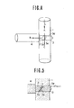
- Fig. 4 is a front view for explaining another embodiment of the light diverting device according to the present invention
- Fig. 5 is a cross-sectional view thereof.
- the third optical conductor rod 3 is tightly inserted into the through-hole so as to be able to move back and forth.
- a groove 3d is bored at the upper edge-portion of the third optical conductor rod 3 along the same direction as the shaft.
- Optical oil is poured through the groove 3d into the gap d between the inclined surface 2a of the second optical conductor rod 2 and the inclined surface 3a of the third one 3.
- the third optical conductor rod 3 moves back and forth the air in the gap is released outside or contrarily air is taken into the gap in order to facilitate the movement of the third optical conductor rod 3.
- the light rays L are directed in the direction shown by arrow C where optical oil present.
- the amount of light rays propagated in the direction of B can be adjusted in accordance with the level of optical oil in the gap. It may be possible to change the condition of its adjustment by changing the insertion depth of the third optical conductor rod 3.
Landscapes
- Physics & Mathematics (AREA)
- General Physics & Mathematics (AREA)
- Optics & Photonics (AREA)
- Engineering & Computer Science (AREA)
- General Engineering & Computer Science (AREA)
- Optical Couplings Of Light Guides (AREA)
- Lasers (AREA)
Applications Claiming Priority (4)
| Application Number | Priority Date | Filing Date | Title |
|---|---|---|---|
| JP58211643A JPS60103318A (ja) | 1983-11-10 | 1983-11-10 | 光分岐装置 |
| JP211643/83 | 1983-11-10 | ||
| JP215810/83 | 1983-11-16 | ||
| JP21581083A JPS60107605A (ja) | 1983-11-16 | 1983-11-16 | 光分岐装置 |
Publications (2)
| Publication Number | Publication Date |
|---|---|
| EP0142774A2 true EP0142774A2 (de) | 1985-05-29 |
| EP0142774A3 EP0142774A3 (de) | 1987-05-20 |
Family
ID=26518762
Family Applications (1)
| Application Number | Title | Priority Date | Filing Date |
|---|---|---|---|
| EP84113379A Withdrawn EP0142774A3 (de) | 1983-11-10 | 1984-11-06 | Vorrichtung zur Lichtablenkung |
Country Status (5)
| Country | Link |
|---|---|
| US (1) | US4636028A (de) |
| EP (1) | EP0142774A3 (de) |
| AU (1) | AU565338B2 (de) |
| CA (1) | CA1251973A (de) |
| NZ (1) | NZ210116A (de) |
Families Citing this family (7)
| Publication number | Priority date | Publication date | Assignee | Title |
|---|---|---|---|---|
| JPS60138510A (ja) * | 1983-12-27 | 1985-07-23 | Takashi Mori | 光分岐装置 |
| US4699450A (en) * | 1984-06-28 | 1987-10-13 | Kei Mori | Device for diverting a portion of light energy transmitted through an optical conductor |
| US4989932A (en) * | 1989-03-03 | 1991-02-05 | Lt Industries | Multiplexer for use with a device for optically analyzing a sample |
| US5097396A (en) * | 1990-09-25 | 1992-03-17 | Poly-Optical Products, Inc. | Fiber optic backlighting panel |
| US5287423A (en) * | 1991-01-31 | 1994-02-15 | L. T. Industries, Inc. | Multiplexer for use with a device for optically analyzing a sample |
| US5307245A (en) * | 1991-06-27 | 1994-04-26 | Poly-Optical Products, Inc. | Fiber optic backlighting panel and zig-zag process for making same |
| US5852693A (en) * | 1996-11-26 | 1998-12-22 | Ultratech Stepper, Inc. | Low-loss light redirection apparatus |
Family Cites Families (25)
| Publication number | Priority date | Publication date | Assignee | Title |
|---|---|---|---|---|
| US3416089A (en) * | 1964-04-03 | 1968-12-10 | American Optical Corp | Laser amplifier construction |
| US3874779A (en) * | 1973-07-05 | 1975-04-01 | Corning Glass Works | Variable ratio light coupler |
| DE2340019A1 (de) * | 1973-08-07 | 1975-02-20 | Siemens Ag | Kopplung fuer lichtleitfasern untereinander und fuer lichtleitfasern mit endgeraeten |
| CH599558A5 (de) * | 1976-03-16 | 1978-05-31 | Patelhold Patentverwertung | |
| US4057719A (en) * | 1976-08-27 | 1977-11-08 | The United States Of America As Represented By The Secretary Of The Navy | Fiber optics electro-mechanical light switch |
| US4121884A (en) * | 1976-10-08 | 1978-10-24 | International Standard Electric Corporation | Optical fiber switch |
| US4130345A (en) * | 1977-02-25 | 1978-12-19 | The Boeing Company | Optical coupling apparatus |
| DE2744128A1 (de) * | 1977-09-30 | 1979-04-12 | Siemens Ag | Wellenleiter mit einem laengsseits angeordneten detektor |
| US4165496A (en) * | 1977-12-16 | 1979-08-21 | Bell Telephone Laboratories, Incorporated | Optical fiber light tap |
| FR2428333A1 (fr) * | 1978-06-09 | 1980-01-04 | Thomson Csf | " laser " a reflecteur distribue |
| DE2851646A1 (de) * | 1978-11-29 | 1980-07-17 | Siemens Ag | Koppelelement zum auskoppeln eines lichtanteils aus einem optischen wellenleiter und wiedereinkoppeln desselben in einen abzweigenden optischen wellenleiter |
| DE2851667A1 (de) * | 1978-11-29 | 1980-07-10 | Siemens Ag | Abzweigelement fuer monomode-lichtwellenleiter und verfahren zu seiner herstellung |
| JPS55105206A (en) * | 1979-02-05 | 1980-08-12 | Fujitsu Ltd | Optical branching and coupling circuit |
| DE2938810A1 (de) * | 1979-09-25 | 1981-04-09 | Siemens AG, 1000 Berlin und 8000 München | Vorrichtung zum einkoppeln von strahlung in einen optischen wellenleiter |
| JPS5685703A (en) * | 1979-12-14 | 1981-07-13 | Fujitsu Ltd | Production of branching circuit |
| US4296995A (en) * | 1980-02-01 | 1981-10-27 | International Telephone And Telegraph Corporation | Optical fiber beam splitter couplers employing coatings with dichroic properties |
| US4452505A (en) * | 1980-04-02 | 1984-06-05 | International Telephone And Telegraph Corporation | Bidirectional coupler for communication over a single fiber |
| US4373775A (en) * | 1980-06-23 | 1983-02-15 | International Telephone And Telegraph Corporation | Fiber dichroic coupler |
| US4387954A (en) * | 1981-01-19 | 1983-06-14 | Gould Inc. | Method for fabricating an optical waveguide evanescent wave coupler having an interleaved film |
| US4468567A (en) * | 1981-05-21 | 1984-08-28 | Showa Electric Wire & Cable Co., Ltd. | Liquid level detecting device and method for producing the same |
| DE3138968A1 (de) * | 1981-09-30 | 1983-04-14 | Siemens AG, 1000 Berlin und 8000 München | Optische steuervorrichtung zum steuern der in einem optischen wellenleiter gefuehrten strahlung, insbesondere optischer schalter |
| US4431262A (en) * | 1981-10-06 | 1984-02-14 | Tolles Walter E | Conformable optical couplers |
| FR2525777B1 (fr) * | 1982-04-21 | 1985-11-15 | Renault | Coupleur lateral ou transversal pour fibres optiques |
| DE3303160A1 (de) * | 1983-01-31 | 1984-08-02 | Siemens AG, 1000 Berlin und 8000 München | Vorrichtung zur auskopplung oder einkopplung von licht bei einem lichtwellenleiter |
| DE3310587A1 (de) * | 1983-03-23 | 1984-09-27 | Siemens AG, 1000 Berlin und 8000 München | Lichtwellenleiterverzweigung, ihre anwendung und verfahren zu ihrer herstellung |
-
1984
- 1984-11-05 US US06/668,228 patent/US4636028A/en not_active Expired - Fee Related
- 1984-11-06 NZ NZ210116A patent/NZ210116A/xx unknown
- 1984-11-06 EP EP84113379A patent/EP0142774A3/de not_active Withdrawn
- 1984-11-07 CA CA000467270A patent/CA1251973A/en not_active Expired
- 1984-11-07 AU AU35167/84A patent/AU565338B2/en not_active Ceased
Also Published As
| Publication number | Publication date |
|---|---|
| NZ210116A (en) | 1988-10-28 |
| CA1251973A (en) | 1989-04-04 |
| US4636028A (en) | 1987-01-13 |
| AU3516784A (en) | 1985-05-16 |
| EP0142774A3 (de) | 1987-05-20 |
| AU565338B2 (en) | 1987-08-04 |
Similar Documents
| Publication | Publication Date | Title |
|---|---|---|
| DE3751213D1 (de) | Optisches Kabel mit nichtmetallischem Mantel. | |
| EP0173343A2 (de) | Solarenergiekondensor | |
| IT1212819B (it) | Cambio automatico a velocita'variabile. | |
| EP0113375A4 (de) | Übersetzungsgetriebe. | |
| AR241128A1 (es) | "un cable optico submarino". | |
| DE3866494D1 (de) | Drehzahlsteuerung fuer verbrennungsmotoren mit automatikgetriebe. | |
| US4636028A (en) | Light diverting device | |
| US4690490A (en) | Light diverting device | |
| AU8847982A (en) | Transverse type automatic transmission with through lay shaft | |
| ES515317A0 (es) | Perfeccionamientos en una cabeza opto-electronica de transmision. | |
| DE68919123D1 (de) | Automatisches Fokussierungssystem für Kameras mit einer Variooptikfunktion. | |
| EP0173344A2 (de) | Leicht fokussierende Linse | |
| US4684209A (en) | Device for diverting light through a plurality of optical conductor rods | |
| ES548885A0 (es) | Perfeccionamientos en un dispositivo de accionamiento meca- nico por cables con reglaje automatico | |
| DE3381480D1 (de) | Sonarwandler mit vielfachbuendellinze. | |
| IT8223263A0 (it) | Differenziale automatico con un rotismo epicicloidale di riduzione e un rotismo epicicloidale collettore. | |
| DE68904859D1 (de) | Elektronenstrahlroehre mit wendelfokussierlinse. | |
| ES293419Y (es) | Un cable optico. | |
| IT7921943A0 (it) | Cono di sincronizzatore per scatole cambio di velocita' a rapporti a stadi. | |
| IT1143481B (it) | Cambio meccanico con rapporto lungo automatico | |
| IT8224033A0 (it) | Gruppo di propulsione con un cambio. | |
| JPS6256486B2 (de) | ||
| IT8204832A0 (it) | Palettizzatore automatico a funzionamento meccanico. | |
| KR880003038Y1 (ko) | 광분기 기구(光分岐機構) | |
| BE896680A (fr) | Arme legere automatique. |
Legal Events
| Date | Code | Title | Description |
|---|---|---|---|
| PUAI | Public reference made under article 153(3) epc to a published international application that has entered the european phase |
Free format text: ORIGINAL CODE: 0009012 |
|
| AK | Designated contracting states |
Designated state(s): CH DE FR GB IT LI NL SE |
|
| PUAL | Search report despatched |
Free format text: ORIGINAL CODE: 0009013 |
|
| AK | Designated contracting states |
Kind code of ref document: A3 Designated state(s): CH DE FR GB IT LI NL SE |
|
| 17P | Request for examination filed |
Effective date: 19871117 |
|
| 17Q | First examination report despatched |
Effective date: 19890728 |
|
| STAA | Information on the status of an ep patent application or granted ep patent |
Free format text: STATUS: THE APPLICATION HAS BEEN WITHDRAWN |
|
| 18W | Application withdrawn |
Withdrawal date: 19900531 |
|
| R18W | Application withdrawn (corrected) |
Effective date: 19900531 |