EP0142781A2 - Assemblage à glisseur pour tête magnétique - Google Patents
Assemblage à glisseur pour tête magnétique Download PDFInfo
- Publication number
- EP0142781A2 EP0142781A2 EP84113479A EP84113479A EP0142781A2 EP 0142781 A2 EP0142781 A2 EP 0142781A2 EP 84113479 A EP84113479 A EP 84113479A EP 84113479 A EP84113479 A EP 84113479A EP 0142781 A2 EP0142781 A2 EP 0142781A2
- Authority
- EP
- European Patent Office
- Prior art keywords
- composition
- oxide
- zirconium oxide
- magnetic head
- yttrium oxide
- Prior art date
- Legal status (The legal status is an assumption and is not a legal conclusion. Google has not performed a legal analysis and makes no representation as to the accuracy of the status listed.)
- Withdrawn
Links
Images
Classifications
-
- G—PHYSICS
- G11—INFORMATION STORAGE
- G11B—INFORMATION STORAGE BASED ON RELATIVE MOVEMENT BETWEEN RECORD CARRIER AND TRANSDUCER
- G11B5/00—Recording by magnetisation or demagnetisation of a record carrier; Reproducing by magnetic means; Record carriers therefor
- G11B5/10—Structure or manufacture of housings or shields for heads
-
- C—CHEMISTRY; METALLURGY
- C04—CEMENTS; CONCRETE; ARTIFICIAL STONE; CERAMICS; REFRACTORIES
- C04B—LIME, MAGNESIA; SLAG; CEMENTS; COMPOSITIONS THEREOF, e.g. MORTARS, CONCRETE OR LIKE BUILDING MATERIALS; ARTIFICIAL STONE; CERAMICS; REFRACTORIES; TREATMENT OF NATURAL STONE
- C04B35/00—Shaped ceramic products characterised by their composition; Ceramics compositions; Processing powders of inorganic compounds preparatory to the manufacturing of ceramic products
- C04B35/01—Shaped ceramic products characterised by their composition; Ceramics compositions; Processing powders of inorganic compounds preparatory to the manufacturing of ceramic products based on oxide ceramics
- C04B35/48—Shaped ceramic products characterised by their composition; Ceramics compositions; Processing powders of inorganic compounds preparatory to the manufacturing of ceramic products based on oxide ceramics based on zirconium or hafnium oxides, zirconates, zircon or hafnates
- C04B35/486—Fine ceramics
-
- G—PHYSICS
- G11—INFORMATION STORAGE
- G11B—INFORMATION STORAGE BASED ON RELATIVE MOVEMENT BETWEEN RECORD CARRIER AND TRANSDUCER
- G11B5/00—Recording by magnetisation or demagnetisation of a record carrier; Reproducing by magnetic means; Record carriers therefor
- G11B5/127—Structure or manufacture of heads, e.g. inductive
- G11B5/31—Structure or manufacture of heads, e.g. inductive using thin films
- G11B5/3103—Structure or manufacture of integrated heads or heads mechanically assembled and electrically connected to a support or housing
- G11B5/3106—Structure or manufacture of integrated heads or heads mechanically assembled and electrically connected to a support or housing where the integrated or assembled structure comprises means for conditioning against physical detrimental influence, e.g. wear, contamination
Definitions
- This invention relates to a magnetic head slider assembly, and particularly to a material for the slider and a process for the preparation of the material.
- the slider on which a magnetic transducer is mounted is generally used for floating a magnetic head in a magnetic disk unit.
- slider materials desirable for thin-film magnetic heads have been those which are superior in machining properties and suitable for shaping into high-precision components, such'as the thin-film magnetic head, as described in the U.S. Patent No. 4,251,841.
- the material of the magnetic head used in a magnetic disk unit especially must be able to withstand contact trouble arising between the magnetic disk and the magnetic head, i.e. the head crush.
- the magnetic head In the stationary condition, the magnetic head is normally kept afloat above the rotating magnetic disk surface with a space of 0.2 to 0.5 ⁇ m.
- the transient condition for the magnetic disk to reach a steady revolution or in a stop condition, there arises a phenomenon in which the magnetic disk and the head slider are sliding in contact with each other.
- the properties required of a substrate for a thin-film magnetic head assembly are firstly that the substrate is chemical and heat stable without undergoing corrosion or deformation in the process of forming a thin-film element. Secondly, it must easily provide dimensional accuracy when machined into a slider and must be easy to cut, grind and polish. Thirdly it must possess a superior sliding property with regard to the magnetic disk.
- an object of the present invention is to provide a magnetic head slider having superior sliding characteristics with regard to a magnetic disk.
- Zirconium oxide has been a material difficult to calcine because it assumes three different crystal forms, i.e. monoclinic structure, tetragonal structure and cubic structure, which are stable in their respective temperature ranges.
- zirconium oxide which has been sintered at a high temperature is transformed from the cubic to the tetragonal structure and from the tetragonal to the monoclinic structure in the process of cooling to room temperature, and the sintered product undergoes volume change or cracking at each transformation.
- zirconium oxide, whose phase is stable at a high temperature to assume a stable phase even at room temperature by incorporating therein yttrium oxide (Y 0 ) or 2 3 calcium oxide as a solid solution.
- Partially stabilized zirconia was produced by incorporating zirconium oxide, for example, with 2 to 4 mol % of yttrium oxide as a solid solution, thereby enabling it to maintain its tetragonal structure in a stable form which is normally unstable at room temperature. Nevertheless, when this partially stabilized zirconia is used for a thin-film magnetic head substrate by laminating with an insulator layer, a conductor and a magnetic material and then subjecting the laminate to a heat cycle, its crystal form is altered from the tetragonal to the monoclinic structure, followed by a volume expansion due to the transformation. As the result, there occurs a positional deviation between the pattern formed in the initial stage of the process and the one formed in the later stage. !
- yttrium oxide or calcium oxide in larger amounts to zirconium oxide.
- zirconium oxide is sintered with the addition of 6 to 11 mol X, preferably 8 to 10 mol X, of yttrium oxide, its cubic structure, normally stable only at a high temperatures, is still present at room temperature. Accordingly the above material acquires an improved machining property and is prevented from phase transformation during machining.
- the resulting magnetic head slider possesses an excellent sliding property with regard to the magnetic disk.
- Figure 1 shows a magnetic head slider assembly having a thin-film magnetic head element.
- a slider 1 is formed by machining a substrate. It has an air bearing surface 10 which includes spaced rails 111 and 112 which contribute to the float relative to the surface of a rotating magnetic disk.
- a thin-film magnetic head element 2 is mounted on the end of slider 1.
- the thin-film magnetic head element 2 has at least one magnetic transducer 211 to record data on the magnetic disk. Another magnetic transducer 212 is provided for compensation.
- the thin-film magnetic head element 2 also has terminals 22 to lead electric lines thereto.
- the above substrate is prepared as the following.
- Powdery zirconium oxide (ZrO ) having a purity of 99.5% was . 2 mixed with powdery yttrium oxide (Y 0 ) having a purity of 99.5% 2 3 in amounts of 3, 4, 6 and 10 mol %, respectively, in a ball mill, and each mixture was then sintered by means of a hot press in vacuo to give a zirconium oxide composition.
- a thin-film magnetic head assembly was prepared using the resulting zirconium oxide as the substrate.
- Table 1 shows their crystal forms determined by X-ray diffractometry, contact start stop (CSS) lie and cut resistance for each respective mol %.
- the X-ray diffraction pattern was observed using Cu as target under an accelerating voltage of 40 kV and a current of 30 mA.
- the CSS life was represented by the number of revolutions observed at a peripheral speed of 50 m/s until reaching a head crush by comparing with that of the Al 0 .TiC material.
- the cut 2 3 resistance was represented by the electric power required for cutting off a 4-mm thick substrate with a grinder consisting of metal-bonded 1400 diamond grains by comparing with that of the Al O TiC. 2 3
- the X-ray diffraction patterns have revealed that the substrate made of zirconium oxide and 3 or 4 mol % of yttrium oxide is composed of two crystal phases, i.e. monoclinic and tetragonal, and that the substrate made of zirconium oxide incorporated with 6 or 10 mol % of yttrium oxide is composed of a single cubic phase, which never transforms to the tetragonal or monoclinic phase even with machining.
- the above results indicate that the partially stabilized zirconia incorporated with 3 or 4 mol % of yttrium oxide is hard to machine, which is also evident from the comparison of the cut resistance as shown in the table.
- zirconium oxide samples are superior to AlO .TiC in 2 3 CSS life as shown. Taking into consideration the machining property, the zirconium oxide consisting of cubic crystals which are stable at room temperature, is evidently advantageous in use as a substrate for a thin-film magnetic head slider assembly.
- powdery zirconium oxide having a purity of 99.5% was mixed in a ball mill with powdery yttrium oxide having a purity of 99.5% in amounts ranging from 3 to 13 mol %, at intervals of 1 mol %, and each mixture was then sintered by means of a hot press in vacuo to give a zirconium oxide composition.
- a thin-film magnetic head was prepared using the resulting zirconium oxide as the substrate.
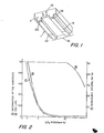
- Figure 2 is a graph showing the content of-.monoclinic crystals (C) in the sintered zirconium oxide being ground in the ball mill, the deformation of the substrate being processed into a thin-film magnetic head element (A), and the CSS life (B), which are plotted against the quantity of yttrium oxide incorporated in zirconium oxide.
- the content of monoclinic crystals was observed by X-ray diffractometry with an accelerating voltage of 40 kV and a current of 30 mA, using Cu as target.
- the deformation of the substrate was observed by sputtering the substrate, 3 inch square and 4 mm thick, with an alumina protective coat, 30 ⁇ m, by means of a high-frequency bias device.
- the CSS life was represented by the number of revolutions observed at a peripheral speed of 50 m/s until reaching a head crush.
- the values shown herein are compared by setting the value obtained on adding 3 mol X of yttrium oxide as 1.
- the yttrium oxide content in the sintered zirconium oxide composition is increased, tetragonal crystals remaining therein will decrease and cubic crystals will increase, so that the volume expansion due to the stress-induced transformation as well as the deformation of the substrate will decrease as the substrate is being processed into the thin-film magnetic head element.
- the yttrium oxide content in the zirconium oxide should be in a range of 6 to 11 mol %, preferably 8 to 10 mol %, in order to minimize the deformation of the substrate due to the phase transformation of zirconium oxide and moreover to provide the substrate with sufficient CSS life and excellent machining properties.
Landscapes
- Engineering & Computer Science (AREA)
- Chemical & Material Sciences (AREA)
- Manufacturing & Machinery (AREA)
- Ceramic Engineering (AREA)
- Composite Materials (AREA)
- Materials Engineering (AREA)
- Structural Engineering (AREA)
- Organic Chemistry (AREA)
- Adjustment Of The Magnetic Head Position Track Following On Tapes (AREA)
- Compositions Of Oxide Ceramics (AREA)
- Magnetic Heads (AREA)
Applications Claiming Priority (2)
| Application Number | Priority Date | Filing Date | Title |
|---|---|---|---|
| JP210871/83 | 1983-11-11 | ||
| JP21087183A JPS60103515A (ja) | 1983-11-11 | 1983-11-11 | 薄膜磁気ヘツド |
Publications (2)
| Publication Number | Publication Date |
|---|---|
| EP0142781A2 true EP0142781A2 (fr) | 1985-05-29 |
| EP0142781A3 EP0142781A3 (fr) | 1987-01-14 |
Family
ID=16596478
Family Applications (1)
| Application Number | Title | Priority Date | Filing Date |
|---|---|---|---|
| EP84113479A Withdrawn EP0142781A3 (fr) | 1983-11-11 | 1984-11-08 | Assemblage à glisseur pour tête magnétique |
Country Status (2)
| Country | Link |
|---|---|
| EP (1) | EP0142781A3 (fr) |
| JP (1) | JPS60103515A (fr) |
Cited By (5)
| Publication number | Priority date | Publication date | Assignee | Title |
|---|---|---|---|---|
| EP0137134B1 (fr) * | 1983-09-21 | 1989-05-10 | Hitachi Metals, Ltd. | Tête magnétique à substrat non magnétique |
| GB2225144A (en) * | 1988-09-17 | 1990-05-23 | Tokin Corp | Magnetic head with an improved wear-resistant surface against a recording medium |
| FR2664419A1 (fr) * | 1990-06-21 | 1992-01-10 | Sumitomo Spec Metals | Materiau pour piece de glissement de tete magnetique. |
| US5104483A (en) * | 1989-01-09 | 1992-04-14 | Ngk Insulators, Ltd. | Method of producing a negative-pressure type magnetic head slider |
| US6556389B1 (en) * | 1998-06-04 | 2003-04-29 | Seagate Technology, L.L.C. | Method for thermally isolating a magnetoresistive element from thermal asperities |
Families Citing this family (1)
| Publication number | Priority date | Publication date | Assignee | Title |
|---|---|---|---|---|
| US6435016B1 (en) * | 2000-03-24 | 2002-08-20 | Saint-Gobain Ceramics & Plastics, Inc. | Head gimbal assembly, test device and slider for use therewith |
Family Cites Families (3)
| Publication number | Priority date | Publication date | Assignee | Title |
|---|---|---|---|---|
| JPS4826527B1 (fr) * | 1969-02-13 | 1973-08-11 | ||
| FR2475531A1 (fr) * | 1980-02-08 | 1981-08-14 | Commissariat Energie Atomique | Procede de preparation de pieces en electrolyte solide a base de zircone stabilisee et les pieces obtenues par ce procede |
| US4360598A (en) * | 1980-03-26 | 1982-11-23 | Ngk Insulators, Ltd. | Zirconia ceramics and a method of producing the same |
-
1983
- 1983-11-11 JP JP21087183A patent/JPS60103515A/ja active Pending
-
1984
- 1984-11-08 EP EP84113479A patent/EP0142781A3/fr not_active Withdrawn
Cited By (6)
| Publication number | Priority date | Publication date | Assignee | Title |
|---|---|---|---|---|
| EP0137134B1 (fr) * | 1983-09-21 | 1989-05-10 | Hitachi Metals, Ltd. | Tête magnétique à substrat non magnétique |
| GB2225144A (en) * | 1988-09-17 | 1990-05-23 | Tokin Corp | Magnetic head with an improved wear-resistant surface against a recording medium |
| US5104483A (en) * | 1989-01-09 | 1992-04-14 | Ngk Insulators, Ltd. | Method of producing a negative-pressure type magnetic head slider |
| FR2664419A1 (fr) * | 1990-06-21 | 1992-01-10 | Sumitomo Spec Metals | Materiau pour piece de glissement de tete magnetique. |
| US5432016A (en) * | 1990-06-21 | 1995-07-11 | Sumitomo Special Metals Co., Ltd. | Magnetic head slider material |
| US6556389B1 (en) * | 1998-06-04 | 2003-04-29 | Seagate Technology, L.L.C. | Method for thermally isolating a magnetoresistive element from thermal asperities |
Also Published As
| Publication number | Publication date |
|---|---|
| JPS60103515A (ja) | 1985-06-07 |
| EP0142781A3 (fr) | 1987-01-14 |
Similar Documents
| Publication | Publication Date | Title |
|---|---|---|
| EP0153141B1 (fr) | Têtes magnétiques à films minces | |
| US4681813A (en) | Ceramic substrate for a thin layer magnetic head | |
| US4598052A (en) | Alumina base substrate of recording head and process for the production thereof | |
| JPH0319184B2 (fr) | ||
| EP0142781A2 (fr) | Assemblage à glisseur pour tête magnétique | |
| US5246893A (en) | Ceramic sintered body and process for preparation thereof | |
| US5432016A (en) | Magnetic head slider material | |
| EP0137134B1 (fr) | Tête magnétique à substrat non magnétique | |
| JPH0332202B2 (fr) | ||
| JPS61106455A (ja) | ジルコニアセラミツクス | |
| JPH06329463A (ja) | 磁気ヘッド用非磁性基板材料 | |
| JPH02180754A (ja) | 磁気ヘッドのスライダ | |
| JPS6066361A (ja) | 磁気ヘツド | |
| Tashiro et al. | Fabrication of Pb (Zr, Ti) O3 ceramics from fine particle powder with excess PbO and their piezoelectric properties | |
| JPH0335258B2 (fr) | ||
| JP2616800B2 (ja) | セラミック焼結体の製法 | |
| JP3078302B2 (ja) | 非磁性セラミック組成物 | |
| JPH05246763A (ja) | セラミックス焼結体 | |
| CN85101172A (zh) | 磁头滑块组件 | |
| JPS6398816A (ja) | 薄膜磁気ヘツド用基板およびその製造方法 | |
| JPS63134559A (ja) | 磁気ヘツド用非磁性セラミツクス | |
| JPS6110052A (ja) | 薄膜磁気ヘツド用基板材料 | |
| JPS6152101B2 (fr) | ||
| EP0157487A1 (fr) | Comprimés céramiques qui contiennent du zircone | |
| JPH01294571A (ja) | 薄膜磁気ヘッド・スライダ材料 |
Legal Events
| Date | Code | Title | Description |
|---|---|---|---|
| PUAI | Public reference made under article 153(3) epc to a published international application that has entered the european phase |
Free format text: ORIGINAL CODE: 0009012 |
|
| AK | Designated contracting states |
Designated state(s): DE FR GB |
|
| PUAL | Search report despatched |
Free format text: ORIGINAL CODE: 0009013 |
|
| AK | Designated contracting states |
Kind code of ref document: A3 Designated state(s): DE FR GB |
|
| 17P | Request for examination filed |
Effective date: 19870115 |
|
| 17Q | First examination report despatched |
Effective date: 19880212 |
|
| STAA | Information on the status of an ep patent application or granted ep patent |
Free format text: STATUS: THE APPLICATION HAS BEEN WITHDRAWN |
|
| 18W | Application withdrawn |
Withdrawal date: 19880923 |
|
| RIN1 | Information on inventor provided before grant (corrected) |
Inventor name: TAKESHITA, KOHJI Inventor name: NAKAJIMA, HIROYASU Inventor name: NAGAIKE, SADANORI Inventor name: OHURA, MASAKI |