EP0142814A2 - Machine de vente avec ensemble de crédit - Google Patents
Machine de vente avec ensemble de crédit Download PDFInfo
- Publication number
- EP0142814A2 EP0142814A2 EP84113689A EP84113689A EP0142814A2 EP 0142814 A2 EP0142814 A2 EP 0142814A2 EP 84113689 A EP84113689 A EP 84113689A EP 84113689 A EP84113689 A EP 84113689A EP 0142814 A2 EP0142814 A2 EP 0142814A2
- Authority
- EP
- European Patent Office
- Prior art keywords
- switch
- self
- coin
- seller
- switching contact
- Prior art date
- Legal status (The legal status is an assumption and is not a legal conclusion. Google has not performed a legal analysis and makes no representation as to the accuracy of the status listed.)
- Granted
Links
Images


Classifications
-
- G—PHYSICS
- G07—CHECKING-DEVICES
- G07F—COIN-FREED OR LIKE APPARATUS
- G07F5/00—Coin-actuated mechanisms; Interlocks
- G07F5/20—Coin-actuated mechanisms; Interlocks specially adapted for registering coins as credit, e.g. mechanically actuated
- G07F5/22—Coin-actuated mechanisms; Interlocks specially adapted for registering coins as credit, e.g. mechanically actuated electrically actuated
Definitions
- the invention relates to a self-seller with a coin inlet, a credit facility and a cash register, the credit being deleted when the coin is returned, with several goods dispensing devices, of which only one can be actuated by a mechanical locking device, and with a locking bar common to all goods dispensing devices and a locking piece , which releases the locking bar for shifting when the credit is equal to the selling price, with the intermediate checkout in the checkout position.
- Such a self-seller is described in DE-OS 29 13 431. This self-seller works purely mechanically regardless of a power supply. All Control and locking functions are achieved by mechanical means.
- the credit facility that captures the inserted coins is a mechanical credit facility. Such a credit facility is complex.
- Self-sellers in which the goods dispensing devices are made up of drawers are in practice purely mechanical self-sellers.
- Fully electric self-sellers are also known.
- the goods dispensers are usually controlled by push buttons.
- the goods are ejected by an electromechanical drive, the power consumption of which is high.
- the high power consumption does not bother as long as the self-seller can be connected to the network.
- it makes battery operation of the self-seller practically impossible.
- the task of the invention is to propose a self-seller of the type mentioned at the outset, which takes advantage of mechanical and electrical self-sellers and in which the power consumption is reduced so much that it can be powered by a battery without being connected to the mains.
- battery means a non-rechargeable or a rechargeable (rechargeable) battery.
- the power consumption of this self-seller is low, since only the electronic credit facility and a single electromagnet have to be powered by the battery.
- the other functions, such as goods issue and locking and actuation of the intermediate checkout, are carried out mechanically in a known manner.
- the power consumption is also low because the electronic credit facility is only switched on when the first coin of a sales transaction is inserted and the credit facility and the electromagnet are switched off after the sales transaction.
- the electromagnet is switched on when the loan accrued in the credit facility corresponds to the sales price.
- the battery need not have the power to move components. These movements are carried out by the user by actuating a goods dispensing device.
- the advantages of a mechanical plant are combined with the advantages of an inexpensive electronic credit facility.
- the self-seller is not dependent on a network connection option. Drawers, pushbuttons, flap compartments or drop-down flaps or similar are suitable as goods dispensing devices.
- a fourth switch contact is provided to further save electricity, which only makes the auxiliary switch conductive when an item delivery device is actuated. The blocking piece is therefore only released when the credit has accrued and the user begins to operate a goods issuing device.
- a timing element which blocks the secondary switch if the main switch does not receive a switch-off signal for a certain time after a first coin has been inserted. This avoids that when the user does not properly operate a goods dispensing device, the electromagnet is constantly energized. It is forcibly switched off after a certain time. In order to be able to interpret this certain time briefly, it is expedient if the timer mentioned blocks the secondary switch a certain time after the fourth switching contact has been actuated. This ver The delay time therefore only begins when the user begins to operate one of the output devices. This delay time must therefore only correspond to the usual duration of a complete actuation process. The time between the insertion of the first coin and the selection (start of operation) of one of the goods dispensing devices need not be taken into account in this delay time, which would be the case if the delay time already began with the insertion of the first coin.
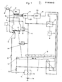
- a first switch contact 2 is arranged, which is in the rest position is open and is closed by a coin when it is run over.
- a coin validator 3 connects to the coin inlet 1. This is followed by four coin shafts 4, which open into an intermediate cash register 5.
- a flap 6 is mounted in the intermediate cash register 5, which is pivoted in the direction of the arrow K in a controlled manner for cashing by a locking bar 7. If the coins of the cash register 5 are to be returned, then a return slide 8 is actuated, which pivots the flap 6 in the direction of the arrow R.
- a third switch contact 9 is provided at the intermediate checkout 5, which is closed in its rest position and is opened when the flap 6 pivots into its return position in the direction of the arrow R,
- the locking bar 7 is coupled to the goods dispensing device 10, for example push buttons or drawers. It is moved in the direction of arrow P when one of the drawers 10 is pulled.
- a mechanical locking device which ensures that only one of the drawers can be pulled at a time, is not shown in detail.
- a locking piece 11 is arranged, which is locked in its rest position.
- the locking piece 11 is assigned an electromagnet 12, which releases the locking of the locking piece 11 when it is energized.
- a second switching contact 13 is arranged, which is closed in its rest position and opens when the Lock bar 7 has exceeded the locking piece 11.
- the switching contacts 2, 9 and 13 are electrically in series. This series connection is located at the control input 14 of a main switch 15.
- the main switch 15 is connected downstream of a battery 16, which is arranged within the self-seller housing.
- a self-holding circuit 17 is provided in parallel with the first switch contact 2 and bridges the switch contact 2 as soon as the main switch 15 is turned on.
- a shift finger 18 is arranged in each of the coin shafts 4.
- the shift finger 18 is pivoted by a falling coin, whereby a counting pulse of appropriate value is given to an electronic credit system 19.
- the respective accrued loan is compared in a comparator 20 with the sales price. If the sales price and the credit match, a secondary switch 21 is switched on.
- the power supply of the credit facility 19 and its zero position takes place via the main switch 15.
- the secondary switch 21, which is located in front of the electromagnet 12, is also connected to the main switch 15.
- a first timer 22 is connected to the secondary switch 21. This opens the secondary switch 21 after a few seconds.
- a second timer 23 with a longer delay time, for example 15 to 20 s, is provided on the self-holding circuit 17 and limits the self-holding time.
- the credit facility 19 works in such a way that a signal is present at a value 1 of the inserted coins at the first output, that at a value 2 of the inserted coins there is a signal at a value 4, at a value 4 of the inserted coins a signal is present at the third output, a signal is present at a value 8 at the fourth output, a signal is present at a value 16 at the fifth output, a signal is present at a value 32 at the sixth output and a signal is present at a value 64 at the seventh output.
- Three switch groups 26, 27 and 28 are arranged in the comparator 20. Each of the switch groups is connected to the seven outputs 25 via diodes. In FIG. 2, the switch that is located at the output of valence 64 is closed in switch group 26.
- each switch group controls a switching transistor T26, T27 and T28 at the base.
- the collectors of the transistors T26, T27 and T28 are connected to the main switch 15.
- the emitters are connected to rails 29, 30 and 31, respectively.
- a fourth switch contact 24 is provided on each of the goods dispensing devices, for example fourteen drawers, of the self-seller. This is open when the drawer is closed and closes when the drawer in question is started to be pulled.
- Each of the switch contacts 24 is connected to one of the rails 29 to 31 via plug connections 32.
- five switch contacts 24 are connected to the rail 29, five switch contacts 24 to the rail 30 and four switch contacts 24 to the rail 31.
- the first five drawers are therefore set to a selling price of value 64, the second five drawers to a selling price of value 32 and the last four drawers to a selling price of value 16.
- the switch contacts 24 are connected to the secondary switch 21 via an inverter J1.
- the main switch 15 has a switching transistor T15, the emitter of which is located at the positive pole of the battery 16.
- the series connection of the switching contacts 9, 13 and 2 is connected in parallel to the base of the transistor T15 via a series resistor R1
- a resistor R2 is connected to the emitter base section of the transistor T15.
- a pole of the coil of the electromagnet 12 is connected to the collector of the transistor T15.
- the supply voltage inputs, not shown in detail, of all integrated components are located on the collector of transistor T15.
- the reset input 33 of the credit facility 19 is also connected to the collector of the transistor T15.
- the collectors of transistors T26, T27 and T28 are on the collector of transistor T15.
- discharge diodes D22 and D23 of timing elements 22 and 23 are connected to the collector of transistor T15.
- the self-holding circuit 17 has a transistor T17, the collector-emitter path of which is parallel to the switching contact 2, a diode D17 being connected in series with the switching contact 2, which ensures a certain minimum voltage at the collector of the transistor T17.
- the secondary switch 21 works with a transistor T21, the collector-emitter path of which is connected in series with the coil of the electromagnet 12. At the base of transistor T21 there are an inverter J2, a NAND gate J3 and a further inverter 14, and a series resistor R3.
- the first timing element 22 has a charging diode D23 and an RC element C22, R22.
- the common pole of the capacitor C22 and the resistor R22 is at one input of the NAND gate J3.
- the resistor 22 is adjustable. For example, it is set so that the delay time is 4 s.
- the second timing element 23 has a charging diode D25 and an RC element C23, R23.
- the common pole of the capacitor C23 and the resistor R23 is connected to the self-holding circuit 17.
- the time constant of the timing element 23 is greater than that of the timing element 22, for example it is 15 to 20 s.
- Inverters J1, J2 are components of an integrated component of type designation 4069.
- Inverters J3 and J4 are components of an integrated component of type designation 4011. Both components are powered by battery 16 after main switch 15 is closed.
- the coin As soon as the coin has failed the coin validator 3, it actuates one of the switching fingers 18, as a result of which the crediting company 19 detects the value of this coin. At this time t2 (cf. FIG. 3), the current consumption increases briefly to 15 mA, for example. If another coin is inserted, then the credit facility 19 also records its value. At this point in time t3, the current consumption increases again briefly.
- the secondary switch 21 is open, the transistor T21 is blocked, so that the blocking piece 11 is locked and therefore none of the drawers 10 can be opened.
- the return slide 8 is actuated.
- the flap 6 swiveling in the direction R slides the coins into a return compartment and opens the switch contact 9. This opens the main switch 15, so that the power consumption drops practically to zero.
- the credit mechanism 19 is again energized and reset. The processes described are repeated.
- a switching signal is present at the fifth output 25 of the credit facility 19.
- the transistor T28 becomes conductive. If now one of the four drawers assigned to this sales price is started to be pulled, then the corresponding switch contact 24 closes, so that the transistor T21 is then turned on via the inverter stages J1, J2, J3 and J4, i. H. the secondary switch 21 closes.
- a current of, for example, 300 mA flows through the coil of the electromagnet 12 at this point in time t5, so that the blocking piece 11 is released.
- the locking bar 7 can move.
- the locking bar 7 pivots the flap 6 in the direction of the arrow K, so that the coins are collected.
- the switch contact 13 opens, so that the main switch 15 also opens. Electricity consumption drops to zero.
- the transistor T21 is not switched, i. H. the auxiliary switch 21 is not closed because the transistor T26 or T27 in question is blocking.
- capacitors C23 and C22 are charged via diodes D25 and D24.
- the delay times T1 and T2 of the timers 22 and 23 begin to run. This is achieved in that as soon as a negative output signal is present at the output of the inverter J1, through which the transistor T21 switches through the inverters J2, J3 and J4, the charging diodes D24 and D25 block, so that the capacitors C22 and C23 have their discharge resistors R22 and R23 begin to discharge.
- the timer 22 switches off the auxiliary switch 21.
- the transistor T21 is blocked via the inverter stages J3 and J4.
- the coil of the electromagnet 12 is de-energized. This reduces the power consumption to approximately 3 mA, the value which is necessary, for example, to operate the credit facility 19 without coin detection. The credit is retained.
- the transistor T15 blocks immediately, so that the entire circuit is switched off.
- the capacitors C22 and C23 are discharged via the diodes D22 and D23.
- the transistors T17 and T21 then turn off.
Landscapes
- Physics & Mathematics (AREA)
- General Physics & Mathematics (AREA)
- Vending Machines For Individual Products (AREA)
- Confectionery (AREA)
- Lock And Its Accessories (AREA)
- Control Of Vending Devices And Auxiliary Devices For Vending Devices (AREA)
Priority Applications (1)
| Application Number | Priority Date | Filing Date | Title |
|---|---|---|---|
| AT84113689T ATE40233T1 (de) | 1983-11-18 | 1984-11-13 | Selbstverkaeufer mit einem kreditwerk. |
Applications Claiming Priority (2)
| Application Number | Priority Date | Filing Date | Title |
|---|---|---|---|
| DE19833341754 DE3341754A1 (de) | 1983-11-18 | 1983-11-18 | Selbstverkaeufer mit einem kreditwerk |
| DE3341754 | 1983-11-18 |
Publications (3)
| Publication Number | Publication Date |
|---|---|
| EP0142814A2 true EP0142814A2 (fr) | 1985-05-29 |
| EP0142814A3 EP0142814A3 (en) | 1987-08-19 |
| EP0142814B1 EP0142814B1 (fr) | 1989-01-18 |
Family
ID=6214671
Family Applications (1)
| Application Number | Title | Priority Date | Filing Date |
|---|---|---|---|
| EP84113689A Expired EP0142814B1 (fr) | 1983-11-18 | 1984-11-13 | Machine de vente avec ensemble de crédit |
Country Status (4)
| Country | Link |
|---|---|
| EP (1) | EP0142814B1 (fr) |
| AT (1) | ATE40233T1 (fr) |
| DE (2) | DE3341754A1 (fr) |
| ES (1) | ES8507716A1 (fr) |
Cited By (1)
| Publication number | Priority date | Publication date | Assignee | Title |
|---|---|---|---|---|
| CN115527308A (zh) * | 2022-09-27 | 2022-12-27 | 深圳市诺丰泰智能科技有限公司 | 一种出货装置以及自动售货机 |
Families Citing this family (1)
| Publication number | Priority date | Publication date | Assignee | Title |
|---|---|---|---|---|
| DE3842935C1 (fr) * | 1988-12-21 | 1989-11-02 | Harting Elektronik Gmbh, 4992 Espelkamp, De |
Family Cites Families (8)
| Publication number | Priority date | Publication date | Assignee | Title |
|---|---|---|---|---|
| DE1235646B (de) * | 1961-09-18 | 1967-03-02 | Harting Elektro W | Kreditspeicher- und Kreditablass-Einrichtung fuer elektrische Warenselbstverkaeufer |
| DE2165293A1 (de) * | 1971-12-23 | 1973-07-05 | Heinrich H Kluessendorf Fa | Selbstverkaeufer mit elektronenrechner |
| DE2237829B2 (de) * | 1972-08-01 | 1977-04-21 | Steuereinrichtung fuer verkaufsautomaten | |
| DE2606894A1 (de) * | 1976-02-20 | 1977-08-25 | Roechling Co Metallwaren | Verkaufseinrichtung fuer zeitungen und zeitschriften |
| DE2825770A1 (de) * | 1978-06-13 | 1980-01-03 | Licentia Gmbh | Schaltungsanordnung zur verminderung der verlustleistung |
| DE2913432C2 (de) * | 1979-04-04 | 1983-11-17 | Sielaff Gmbh & Co Automatenbau Herrieden, 8801 Herrieden | Steuereinrichtung für einen Selbstverkäufer |
| DE2913431A1 (de) * | 1979-04-04 | 1980-10-16 | Sielaff Gmbh Co Automaten | Kassiervorrichtung fuer einen selbstverkaeufer |
| GB2093620B (en) * | 1981-02-11 | 1985-09-04 | Mars Inc | Checking coins |
-
1983
- 1983-11-18 DE DE19833341754 patent/DE3341754A1/de not_active Withdrawn
-
1984
- 1984-11-13 DE DE8484113689T patent/DE3476288D1/de not_active Expired
- 1984-11-13 EP EP84113689A patent/EP0142814B1/fr not_active Expired
- 1984-11-13 AT AT84113689T patent/ATE40233T1/de not_active IP Right Cessation
- 1984-11-16 ES ES537702A patent/ES8507716A1/es not_active Expired
Cited By (1)
| Publication number | Priority date | Publication date | Assignee | Title |
|---|---|---|---|---|
| CN115527308A (zh) * | 2022-09-27 | 2022-12-27 | 深圳市诺丰泰智能科技有限公司 | 一种出货装置以及自动售货机 |
Also Published As
| Publication number | Publication date |
|---|---|
| ES537702A0 (es) | 1985-09-16 |
| ES8507716A1 (es) | 1985-09-16 |
| ATE40233T1 (de) | 1989-02-15 |
| DE3341754A1 (de) | 1985-05-30 |
| EP0142814B1 (fr) | 1989-01-18 |
| DE3476288D1 (en) | 1989-02-23 |
| EP0142814A3 (en) | 1987-08-19 |
Similar Documents
| Publication | Publication Date | Title |
|---|---|---|
| DE2146096A1 (de) | Elektronischer spielautomat nach art eines roulettes | |
| DE2435420C3 (de) | Steuereinrichtung für einen Verkausautomaten | |
| DE2333007C3 (de) | Steuereinrichtung für Verkaufsautomaten | |
| DE1909411C3 (de) | Steuereinrichtung für münzbetätigte Selbstverkäufer | |
| DE2461998A1 (de) | Verkaufsautomat | |
| DE2400066B2 (de) | Anordnung zur Überwachung der Warenauswahl | |
| EP0142814B1 (fr) | Machine de vente avec ensemble de crédit | |
| EP0120347B1 (fr) | Interrupteur horaire | |
| DE3500855A1 (de) | Schaltung eines elektrischen selbstverkaeufers | |
| DE2648514C2 (de) | Verkaufsautomat | |
| DE2254882C3 (de) | Münzgesteuerte Schaltung | |
| DE19902736C2 (de) | Elektronischer Umdrehungszähler | |
| DE2612267C2 (de) | Münz-Spielgerät | |
| DE1082761B (de) | Kreditspeichereinrichtung | |
| DE1774138C (de) | Steuereinrichtung fur einen Verkaufs automaten | |
| DE1474756A1 (de) | Muenzautomat | |
| DE1934832A1 (de) | Fernsteuervorrichtung fuer die Ausgabeeinrichtung von Substanzen mit Vorauszahlung der Entnahmemenge | |
| DE2361384A1 (de) | Steuersystem fuer muenzbetaetigte schlosseinrichtungen an schliessfaechern | |
| DE1916444C3 (de) | Steuereinrichtung für die Restgeldrückgabe bei Verkaufsautomaten | |
| AT224948B (de) | Automatische Waschmaschine, insbesondere für Selbstbedienungs-Waschanstalten | |
| DE2237829B2 (de) | Steuereinrichtung fuer verkaufsautomaten | |
| CH315154A (de) | Elektrische Zähleinrichtung | |
| DE1942132A1 (de) | Steuerschaltung fuer Verkaufsautomaten | |
| DE1182866B (de) | Waehleinrichtung fuer muenzbetaetigte Schallplattenwechsler | |
| DE2619476A1 (de) | Duschanlage |
Legal Events
| Date | Code | Title | Description |
|---|---|---|---|
| PUAI | Public reference made under article 153(3) epc to a published international application that has entered the european phase |
Free format text: ORIGINAL CODE: 0009012 |
|
| AK | Designated contracting states |
Designated state(s): AT CH DE FR GB IT LI |
|
| RTI1 | Title (correction) | ||
| PUAL | Search report despatched |
Free format text: ORIGINAL CODE: 0009013 |
|
| AK | Designated contracting states |
Kind code of ref document: A3 Designated state(s): AT CH DE FR GB IT LI |
|
| 17P | Request for examination filed |
Effective date: 19871124 |
|
| 17Q | First examination report despatched |
Effective date: 19880126 |
|
| GRAA | (expected) grant |
Free format text: ORIGINAL CODE: 0009210 |
|
| AK | Designated contracting states |
Kind code of ref document: B1 Designated state(s): AT CH DE FR GB IT LI |
|
| PG25 | Lapsed in a contracting state [announced via postgrant information from national office to epo] |
Ref country code: IT Free format text: LAPSE BECAUSE OF FAILURE TO SUBMIT A TRANSLATION OF THE DESCRIPTION OR TO PAY THE FEE WITHIN THE PRESCRIBED TIME-LIMIT;WARNING: LAPSES OF ITALIAN PATENTS WITH EFFECTIVE DATE BEFORE 2007 MAY HAVE OCCURRED AT ANY TIME BEFORE 2007. THE CORRECT EFFECTIVE DATE MAY BE DIFFERENT FROM THE ONE RECORDED. Effective date: 19890118 |
|
| REF | Corresponds to: |
Ref document number: 40233 Country of ref document: AT Date of ref document: 19890215 Kind code of ref document: T |
|
| REF | Corresponds to: |
Ref document number: 3476288 Country of ref document: DE Date of ref document: 19890223 |
|
| ET | Fr: translation filed | ||
| GBT | Gb: translation of ep patent filed (gb section 77(6)(a)/1977) | ||
| PG25 | Lapsed in a contracting state [announced via postgrant information from national office to epo] |
Ref country code: AT Effective date: 19891113 |
|
| PLBE | No opposition filed within time limit |
Free format text: ORIGINAL CODE: 0009261 |
|
| STAA | Information on the status of an ep patent application or granted ep patent |
Free format text: STATUS: NO OPPOSITION FILED WITHIN TIME LIMIT |
|
| PG25 | Lapsed in a contracting state [announced via postgrant information from national office to epo] |
Ref country code: LI Effective date: 19891130 Ref country code: CH Effective date: 19891130 |
|
| 26N | No opposition filed | ||
| REG | Reference to a national code |
Ref country code: CH Ref legal event code: PL |
|
| PGFP | Annual fee paid to national office [announced via postgrant information from national office to epo] |
Ref country code: GB Payment date: 19931013 Year of fee payment: 10 |
|
| PGFP | Annual fee paid to national office [announced via postgrant information from national office to epo] |
Ref country code: FR Payment date: 19931028 Year of fee payment: 10 |
|
| PGFP | Annual fee paid to national office [announced via postgrant information from national office to epo] |
Ref country code: DE Payment date: 19931105 Year of fee payment: 10 |
|
| PG25 | Lapsed in a contracting state [announced via postgrant information from national office to epo] |
Ref country code: GB Effective date: 19941113 |
|
| GBPC | Gb: european patent ceased through non-payment of renewal fee |
Effective date: 19941113 |
|
| PG25 | Lapsed in a contracting state [announced via postgrant information from national office to epo] |
Ref country code: FR Effective date: 19950731 |
|
| PG25 | Lapsed in a contracting state [announced via postgrant information from national office to epo] |
Ref country code: DE Effective date: 19950801 |
|
| REG | Reference to a national code |
Ref country code: FR Ref legal event code: ST |