EP0142862A2 - Ultraschallwandler mit einem Polymethylpentengehäuse, gefüllt mit einer Flüssigkeit - Google Patents
Ultraschallwandler mit einem Polymethylpentengehäuse, gefüllt mit einer Flüssigkeit Download PDFInfo
- Publication number
- EP0142862A2 EP0142862A2 EP84114041A EP84114041A EP0142862A2 EP 0142862 A2 EP0142862 A2 EP 0142862A2 EP 84114041 A EP84114041 A EP 84114041A EP 84114041 A EP84114041 A EP 84114041A EP 0142862 A2 EP0142862 A2 EP 0142862A2
- Authority
- EP
- European Patent Office
- Prior art keywords
- ultrasonic probe
- housing
- liquid
- acoustic
- acoustic energy
- Prior art date
- Legal status (The legal status is an assumption and is not a legal conclusion. Google has not performed a legal analysis and makes no representation as to the accuracy of the status listed.)
- Withdrawn
Links
Images
Classifications
-
- G—PHYSICS
- G10—MUSICAL INSTRUMENTS; ACOUSTICS
- G10K—SOUND-PRODUCING DEVICES; METHODS OR DEVICES FOR PROTECTING AGAINST, OR FOR DAMPING, NOISE OR OTHER ACOUSTIC WAVES IN GENERAL; ACOUSTICS NOT OTHERWISE PROVIDED FOR
- G10K11/00—Methods or devices for transmitting, conducting or directing sound in general; Methods or devices for protecting against, or for damping, noise or other acoustic waves in general
- G10K11/02—Mechanical acoustic impedances; Impedance matching, e.g. by horns; Acoustic resonators
-
- G—PHYSICS
- G10—MUSICAL INSTRUMENTS; ACOUSTICS
- G10K—SOUND-PRODUCING DEVICES; METHODS OR DEVICES FOR PROTECTING AGAINST, OR FOR DAMPING, NOISE OR OTHER ACOUSTIC WAVES IN GENERAL; ACOUSTICS NOT OTHERWISE PROVIDED FOR
- G10K11/00—Methods or devices for transmitting, conducting or directing sound in general; Methods or devices for protecting against, or for damping, noise or other acoustic waves in general
- G10K11/18—Methods or devices for transmitting, conducting or directing sound
- G10K11/26—Sound-focusing or directing, e.g. scanning
- G10K11/35—Sound-focusing or directing, e.g. scanning using mechanical steering of transducers or their beams
- G10K11/352—Sound-focusing or directing, e.g. scanning using mechanical steering of transducers or their beams by moving the transducer
- G10K11/355—Arcuate movement
Definitions
- the present invention relates to ultrasonic probes particularly for medical diagnostic purposes, and more particularly to ultrasonic probes of the type wherein piezoelectric transducer is submerged in a liquid medium.
- Ultrasonic probes for medical purposes require that in order to obtain a high quality tomographic image there be a minimum amount of energy loss and a minimum number of reflections of acoustic energy between piezoelectric transducer and human body. Impedance match between them is important in this regard and attempts have been made to seek a material that can be used to match in acoustic impedace with that of the human body.
- Ultrasonic probes of the mechanical scan type wherein the transducer is submerged in a transmitting liquid medium contained in a housing, the material of the housing determines the degree of impedance match.
- the housing is further required to have a sufficient degree of insulation to prevent leakage of electricity, have sufficient mechanical strength and required to be inactive to chemicals, available at low cost and have a sufficient thermal plasticity to lend itself to extrusion process while at the same time it is sufficiently resistive to heat generated during use.
- the present invention is therefore to provide an ultrasonic probe having a piezoelectric transducer submerged in a liquid contained in a probe housing having properties which satisfy the requirements imposed upon it.
- polymethylpentene resin to form at least a part of the probe housing, or acoustic window, which is brought into contact with the human skin.
- Polymethylpentene resin has a number of advantageous physical and chemical properties among which the acoustic impedance value, which is most important, is approximately equal to that of the human body.
- the use of polymethylpentene resin is particularly beneficial to ultrasonic probes of the mechanical scan type of either sector or linear format.
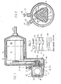
- a mechanical sector-scan ultrasonic probe shown in Fig. 1 comprises a housing 1 which is divided into a hand grip portion 2 and a cylindrical head portion 3.
- An electric motor 4, accommodated in the hand grip portion 2 has a pulley 5 which is connected by a belt 6 to a driven pulley 7 which'in turn drives a rotary shaft 8 supported by bearings 9 and 10 fixed on front and rear walls of the head portion.
- the instantaneous angular position of motor 4 is detected and controlled by a position encoder 4a which is also mounted in the grip portion 2.
- On the rotary shaft 8 are mounted an insulative block 11 of a triangular cross-section (Fig. 2) and the inner winding 14b of a rotary transformer 14.
- Piezoelectric transducers 12a, 12b, 12c are fixedly secured to the sides of block 11. As shown in Fig. 3, first electrodes of transducers 12a, 12b, 12c are coupled together to one terminal of the inner winding 14a of transformer 14 and their second electrodes are coupled to the opposite terminal of the inner winding 14a via reed switches 13a, 13b and 13c, respectively, which are embedded in the rotary block 11 in locations, spaced 120 degrees apart as shown in Fig. 2.
- a permanent magnet 15 is mounted on the rear wall 16 adjacent to the lower arc of a circular path followed by rotating reed switches in order to successively close their contacts as each piezoelectric transducer rotates over a lower arc of its path.
- the head portion 3 is provided with a liquid inlet port 17 and a cap 18 therefor to fill the head portion 3 with a liquid which provides low-loss propagation of acoustic waves. If the liquid contains bubbles, acoustic transmission is adversely affected. To prevent this, the inlet port has a sufficient cross-section to allow bubbles in liquid to escape therethrough while the liquid is being supplied.
- an air vent port 20 with a cap 21 may be provided.
- Ultrasonic burst pulses are supplied from a drive circuit, not shown, through a cable 21 to the outer winding 14b of rotary transformer 14. Pulses are induced in the inner winding 14a and coupled to the piezoelectric transducer by the associated reed switch which is following the lower half of its circular path near the permanent magnet 15, transmitting acoustic energy. Each reed switch remains closed to allow the transmitted energy to be steered in a 'sector format and during this period short-duration bursts are sequentially transmitted at intervals sufficient to receive echos returning from different tissues of a body under examination. The received energy is converted to electrical signals which are coupled through the rotary transformer 14 to a processing circuit to obtain a tomographic ultrasound image of a sector field. As reed switches 13a, 13b, 13c are sequentially closed, piezoelectric transducers 12a, 12b, 12c are likewise energized to effect the transmission and reception of acoustic energy.
- the head portion 3 of the housing is formed of polymethylpentene resin.
- a coloring agent is mixed with the resin.
- the top wall of housing portion 3 has a reduced thickness as shown at 19 to make the inside visible to allow observation of bubbles in the liquid.
- the polymethylpentene resin having recurring units of the formula has the following advantageous properties:
- a further advantageous characteristic of polymethylpentene resin is that its volume resistivity falls within the range of insulators and guarantees excellent protection against current leakage.
- the chemical inactive nature of this material also makes it ideal for use in environment where the ultrasound probe is likely to be stained by chemicals.
- Another advantage is that the thermoplastic nature of the resin lends itself to extrusion process.
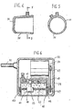
- Figs. 4 and 5 show an alternative embodiment in which the lower half part of the probe head 3, or window 30 may be formed of polymethylpentene resin and the remainder part 31 may be formed of an opaque plastic material which is molded to create an opening to which the polymethslpentene-resin made window 30 is adhesively fitted.
- Fig. 6 shows a linear scan ultrasound probe.
- a piezoelectric transducer 40 of a rectangular or disc shape is fitted below a block 41 threadably mounted on a i horizontal drive shaft 42 rotatably mounted on bearings 43, 44 which are secured on opposite walls of a housing 45 formed of polymethylpentene resin.
- a position encoder 53 slidably mounted on a guide shaft 54 is connected to block 41 .
- the housing 45 is provided with a bubble check window 46 if it is formed of an opaque polymethylpentene resin.
- Drive shaft 42 is connected to pulley 47 connected by a belt 48 and pulley 49 to a revesible motor 50 which is secured to the housing 45.
- Transducer 40 is driven to reciprocate along a straight line to steer transmitted energy to obtain a tomographic image of a rectangular format. All the component parts of the probe are accommodated in an opaque insulative casing 51 to which cable 52 is terminated. Flexible wire connection, not shown, is made from cable 52 to the transducesr 40.
- the use of polymethylpentene resin is also applicable to electronically scanned ultrasound probe, the present invention is particularly advantageous to the mechanically scanned probe as described above since this type of probes necessitates an acoustic low-loss propagation liquid medium which must be contained in a housing.
Landscapes
- Physics & Mathematics (AREA)
- Engineering & Computer Science (AREA)
- Acoustics & Sound (AREA)
- Multimedia (AREA)
- Ultra Sonic Daignosis Equipment (AREA)
- Investigating Or Analyzing Materials By The Use Of Ultrasonic Waves (AREA)
- Transducers For Ultrasonic Waves (AREA)
Applications Claiming Priority (2)
| Application Number | Priority Date | Filing Date | Title |
|---|---|---|---|
| JP58218908A JPS60111644A (ja) | 1983-11-21 | 1983-11-21 | 超音波探触子 |
| JP218908/83 | 1983-11-21 |
Publications (2)
| Publication Number | Publication Date |
|---|---|
| EP0142862A2 true EP0142862A2 (de) | 1985-05-29 |
| EP0142862A3 EP0142862A3 (de) | 1986-04-30 |
Family
ID=16727195
Family Applications (1)
| Application Number | Title | Priority Date | Filing Date |
|---|---|---|---|
| EP84114041A Withdrawn EP0142862A3 (de) | 1983-11-21 | 1984-11-20 | Ultraschallwandler mit einem Polymethylpentengehäuse, gefüllt mit einer Flüssigkeit |
Country Status (2)
| Country | Link |
|---|---|
| EP (1) | EP0142862A3 (de) |
| JP (1) | JPS60111644A (de) |
Cited By (7)
| Publication number | Priority date | Publication date | Assignee | Title |
|---|---|---|---|---|
| FR2606889A1 (fr) * | 1986-11-17 | 1988-05-20 | Shell Int Research | Appareil de production d'images des trous de sonde |
| EP0355175A1 (de) * | 1988-08-17 | 1990-02-28 | Siemens Aktiengesellschaft | Einrichtung zum berührungslosen Zertrümmern von Konkrementen im Körper eines Lebewesens |
| US6773678B2 (en) | 2000-03-20 | 2004-08-10 | Endress + Hauser Conducta Gesellschaft Fur Mess Und Regeltechnik Mbh + Co. | Mounting system and retractable sensor holder for analytical sensors |
| EP1551307A4 (de) * | 2002-10-16 | 2009-06-17 | Envisioneering L L C | Scanning-sonde |
| US8137279B2 (en) | 2001-10-16 | 2012-03-20 | Envisioneering, Llc | Scanning probe |
| US8758256B2 (en) | 2010-07-12 | 2014-06-24 | Best Medical International, Inc. | Apparatus for brachytherapy that uses a scanning probe for treatment of malignant tissue |
| US9044216B2 (en) | 2010-07-12 | 2015-06-02 | Best Medical International, Inc. | Biopsy needle assembly |
Families Citing this family (1)
| Publication number | Priority date | Publication date | Assignee | Title |
|---|---|---|---|---|
| JPS6290610U (de) * | 1985-11-29 | 1987-06-10 |
Family Cites Families (8)
| Publication number | Priority date | Publication date | Assignee | Title |
|---|---|---|---|---|
| US3968459A (en) * | 1975-01-29 | 1976-07-06 | Sperry Rand Corporation | Ultrasonic driver transducer |
| DE2539961A1 (de) * | 1975-09-02 | 1977-10-06 | Friedman | Verfahren und vorrichtung zur verhinderung des keimes oder austreibens sowie zum abtoeten von pflanzen |
| US4149419A (en) * | 1977-11-25 | 1979-04-17 | Smith Kline Instruments, Inc. | Ultrasonic transducer probe |
| CA1153097A (en) * | 1978-03-03 | 1983-08-30 | Jack Jellins | Rotating ultrasonic scanner |
| US4387720A (en) * | 1980-12-29 | 1983-06-14 | Hewlett-Packard Company | Transducer acoustic lens |
| US4398425A (en) * | 1981-08-03 | 1983-08-16 | Dymax Corporation | Ultrasonic scanning transducer |
| JPS59108605U (ja) * | 1983-01-10 | 1984-07-21 | 株式会社日立メデイコ | 超音波断層装置用探触子 |
| JPS59225044A (ja) * | 1983-06-07 | 1984-12-18 | 松下電器産業株式会社 | 超音波トランスジユ−サ |
-
1983
- 1983-11-21 JP JP58218908A patent/JPS60111644A/ja active Granted
-
1984
- 1984-11-20 EP EP84114041A patent/EP0142862A3/de not_active Withdrawn
Cited By (8)
| Publication number | Priority date | Publication date | Assignee | Title |
|---|---|---|---|---|
| FR2606889A1 (fr) * | 1986-11-17 | 1988-05-20 | Shell Int Research | Appareil de production d'images des trous de sonde |
| EP0355175A1 (de) * | 1988-08-17 | 1990-02-28 | Siemens Aktiengesellschaft | Einrichtung zum berührungslosen Zertrümmern von Konkrementen im Körper eines Lebewesens |
| US5031626A (en) * | 1988-08-17 | 1991-07-16 | Siemens Aktiengesellschaft | Extracorporeal lithotripsy apparatus with an ultrasound locating system |
| US6773678B2 (en) | 2000-03-20 | 2004-08-10 | Endress + Hauser Conducta Gesellschaft Fur Mess Und Regeltechnik Mbh + Co. | Mounting system and retractable sensor holder for analytical sensors |
| US8137279B2 (en) | 2001-10-16 | 2012-03-20 | Envisioneering, Llc | Scanning probe |
| EP1551307A4 (de) * | 2002-10-16 | 2009-06-17 | Envisioneering L L C | Scanning-sonde |
| US8758256B2 (en) | 2010-07-12 | 2014-06-24 | Best Medical International, Inc. | Apparatus for brachytherapy that uses a scanning probe for treatment of malignant tissue |
| US9044216B2 (en) | 2010-07-12 | 2015-06-02 | Best Medical International, Inc. | Biopsy needle assembly |
Also Published As
| Publication number | Publication date |
|---|---|
| JPS60111644A (ja) | 1985-06-18 |
| EP0142862A3 (de) | 1986-04-30 |
| JPH0529459B2 (de) | 1993-04-30 |
Similar Documents
| Publication | Publication Date | Title |
|---|---|---|
| CA1127750A (en) | Ultrasonic imaging apparatus | |
| US7400079B2 (en) | Ultrasonic probe | |
| CA2097018A1 (en) | Ultrasonic Transducer Assembly | |
| EP0142862A2 (de) | Ultraschallwandler mit einem Polymethylpentengehäuse, gefüllt mit einer Flüssigkeit | |
| US5050128A (en) | Ultrasonic probe having an ultrasonic propagation medium | |
| US4762002A (en) | Probe array for ultrasonic imaging | |
| DK0648091T3 (da) | Ultralydafbildningssystem | |
| CN101578069A (zh) | 用于三维心腔内超声心动图的导管和包括该导管的系统 | |
| WO1997034288A1 (en) | Direct contact scanner and related method | |
| JPS62106745A (ja) | 植込み可能な超音波探査子とその製法 | |
| US4494548A (en) | Ultrasonic sector scanner | |
| CN104853681B (zh) | 基本声学透明且导电的窗口 | |
| GB2157828A (en) | Ultrasonic imaging apparatus and surgical instrument | |
| Kondo et al. | New tissue mimicking materials for ultrasound phantoms | |
| JPS632616B2 (de) | ||
| WO2008026332A1 (en) | Ultrasonic probe | |
| CN221358235U (zh) | 一种超声波治疗仪探头 | |
| JP3119702B2 (ja) | 体腔内用超音波探触子 | |
| JP3557351B2 (ja) | 超音波プローブ | |
| JP2750787B2 (ja) | 送受並置型の超音波探触子 | |
| JPH0910214A (ja) | 超音波カテーテル | |
| US20070276249A1 (en) | Echographic probe wtih sector scanning using a transducer capable of coming into contact with the structure to be examined | |
| JPS6315943A (ja) | 超音波探触子 | |
| GB2266371A (en) | Ultrasonic oesophageal probe | |
| JPH0722583B2 (ja) | 機械式走査型超音波探触子 |
Legal Events
| Date | Code | Title | Description |
|---|---|---|---|
| PUAI | Public reference made under article 153(3) epc to a published international application that has entered the european phase |
Free format text: ORIGINAL CODE: 0009012 |
|
| AK | Designated contracting states |
Designated state(s): DE FR GB |
|
| PUAL | Search report despatched |
Free format text: ORIGINAL CODE: 0009013 |
|
| AK | Designated contracting states |
Kind code of ref document: A3 Designated state(s): DE FR GB |
|
| 17P | Request for examination filed |
Effective date: 19861015 |
|
| 17Q | First examination report despatched |
Effective date: 19880825 |
|
| STAA | Information on the status of an ep patent application or granted ep patent |
Free format text: STATUS: THE APPLICATION IS DEEMED TO BE WITHDRAWN |
|
| 18D | Application deemed to be withdrawn |
Effective date: 19890110 |
|
| RIN1 | Information on inventor provided before grant (corrected) |
Inventor name: MURAMATSU, FUMIO Inventor name: KAWABUCHI, MASAMI |