EP0142996A2 - Baum zum Befestigen von Schiffen - Google Patents
Baum zum Befestigen von Schiffen Download PDFInfo
- Publication number
- EP0142996A2 EP0142996A2 EP19840308059 EP84308059A EP0142996A2 EP 0142996 A2 EP0142996 A2 EP 0142996A2 EP 19840308059 EP19840308059 EP 19840308059 EP 84308059 A EP84308059 A EP 84308059A EP 0142996 A2 EP0142996 A2 EP 0142996A2
- Authority
- EP
- European Patent Office
- Prior art keywords
- boom
- piston
- mooring
- pneumatic
- ram means
- Prior art date
- Legal status (The legal status is an assumption and is not a legal conclusion. Google has not performed a legal analysis and makes no representation as to the accuracy of the status listed.)
- Withdrawn
Links
- 239000012530 fluid Substances 0.000 claims description 28
- 230000006835 compression Effects 0.000 claims description 6
- 238000007906 compression Methods 0.000 claims description 6
- 230000008602 contraction Effects 0.000 claims description 5
- 238000002347 injection Methods 0.000 claims description 2
- 239000007924 injection Substances 0.000 claims description 2
- 238000005461 lubrication Methods 0.000 claims 2
- 239000000314 lubricant Substances 0.000 description 4
- IJGRMHOSHXDMSA-UHFFFAOYSA-N Atomic nitrogen Chemical compound N#N IJGRMHOSHXDMSA-UHFFFAOYSA-N 0.000 description 2
- 230000002457 bidirectional effect Effects 0.000 description 2
- 238000006073 displacement reaction Methods 0.000 description 2
- 230000007613 environmental effect Effects 0.000 description 2
- 239000010687 lubricating oil Substances 0.000 description 2
- 239000003921 oil Substances 0.000 description 2
- 238000009877 rendering Methods 0.000 description 2
- 230000000295 complement effect Effects 0.000 description 1
- 238000010276 construction Methods 0.000 description 1
- 230000007797 corrosion Effects 0.000 description 1
- 238000005260 corrosion Methods 0.000 description 1
- 230000001419 dependent effect Effects 0.000 description 1
- 230000000694 effects Effects 0.000 description 1
- 239000007789 gas Substances 0.000 description 1
- 210000004907 gland Anatomy 0.000 description 1
- 239000007788 liquid Substances 0.000 description 1
- 230000007257 malfunction Effects 0.000 description 1
- 229910052757 nitrogen Inorganic materials 0.000 description 1
- 230000000452 restraining effect Effects 0.000 description 1
Images


Classifications
-
- F—MECHANICAL ENGINEERING; LIGHTING; HEATING; WEAPONS; BLASTING
- F16—ENGINEERING ELEMENTS AND UNITS; GENERAL MEASURES FOR PRODUCING AND MAINTAINING EFFECTIVE FUNCTIONING OF MACHINES OR INSTALLATIONS; THERMAL INSULATION IN GENERAL
- F16F—SPRINGS; SHOCK-ABSORBERS; MEANS FOR DAMPING VIBRATION
- F16F15/00—Suppression of vibrations in systems; Means or arrangements for avoiding or reducing out-of-balance forces, e.g. due to motion
- F16F15/02—Suppression of vibrations of non-rotating, e.g. reciprocating systems; Suppression of vibrations of rotating systems by use of members not moving with the rotating systems
- F16F15/023—Suppression of vibrations of non-rotating, e.g. reciprocating systems; Suppression of vibrations of rotating systems by use of members not moving with the rotating systems using fluid means
- F16F15/027—Suppression of vibrations of non-rotating, e.g. reciprocating systems; Suppression of vibrations of rotating systems by use of members not moving with the rotating systems using fluid means comprising control arrangements
-
- B—PERFORMING OPERATIONS; TRANSPORTING
- B63—SHIPS OR OTHER WATERBORNE VESSELS; RELATED EQUIPMENT
- B63B—SHIPS OR OTHER WATERBORNE VESSELS; EQUIPMENT FOR SHIPPING
- B63B21/00—Tying-up; Shifting, towing, or pushing equipment; Anchoring
Definitions
- This invention relates to a mooring boom for tethering a floating structure to a tethering station.
- a mooring boom for tethering a floating structure to a tethering station, said boom comprising a first rigid elongate member adapted at one end for secural to said tethering station, a second rigid elongate member adapted at one end for secural to said floating structure, said second member extending in the same direction as said first member and being slidably mounted thereon whereby the boom is of variable length, and pneumatic ram means mounted on the boom and comprising at least one piston and cylinder unit arranged resiliently to resist in at least one direction sliding movement between said members arising from forces imposed on the boom by the floating structure.
- the floating structure may be a sea-going vessel such as an oil tanker or the like and the tethering station may be a fixture or otherwise and that the mooring boom of the present invention by virtue of being semi-rigid in length is resistive to movements of the floating structure resulting from environmental forces such as wind, waves, ice pack motion and the like.
- the first and second rigid elongate members may be mounted telescopically i.e. one being movable within the other, but of course this is not necessary as the members may be mounted side-by-side to fulfil the functional requirement of rendering the boom extensible and contract- able i.e. of variable length.
- the pneumatic ram means may be in the form of a single piston and cylinder unit having a gaseous working fluid and being arranged on the boom to resist extension movements thereof.
- the piston and cylinder unit may be arranged on the boom to resist contraction movements thereof.
- the single piston and cylinder unit may be double-acting and arranged on the boom to resist both extension and contraction movements thereof.
- the pneumatic ram means may be in the form of a pair of back-to-back piston and cylinder units each having a gaseous working fluid and being arranged on the boom to resist both extension and contraction movements thereof.
- the pneumatic ram means may have either its piston or its cylinder secured to one of the first and second elongate members, the non-secured or movable component (i.e. the cylinder or the piston) being actuable by the other of the first and second elongate members.
- the movable component may be directly actuated so that the magnitude of ram movement is the same as the magnitude of boom movement.
- the movable component may be indirectly actuated by way of a cable and pulley system so that the magnitude of ram movement may differ from the magnitude of boom movement.
- the cable and pulley system is arranged so that the magnitude of ram movement is less than the magnitude of boom movement by a factor of 2 or greater.
- the cable and pulley system may take any conventional format such as chain and sprocket.
- the pneumatic ram means may use any form of gaseous working fluid, such as air or nitrogen, which is compressible and preferably the ram means is internally provided with one or more chambers dimensioned to store the working fluid when in its fully compressed state with the piston abutting the cylinder head.
- the pneumatic ram means operates in tension and is provided with one or more chambers dimensioned to store the gaseous working fluid when the piston abuts the cylinder back wall.
- a pneumatic control system is connected to the ram means and arranged to determine the initial pressure of the working fluid. The control system may also determine limits of compression rate of the working fluid by dynamic injection or exhaust of working fluid.
- boom 10 is formed by a first rigid elongate member 11 which at its end 11A is secured for example by means of pin 12 to a tethering station 13 which in this instance is illustrated as being a fixture.
- Boom 10 also includes a second rigid elongate member 14 having an end 14A to which is secured a floating structure 15 in this instance in the form of a sea-going vessel.
- Member 14 extends in the same direction as member 11 and is slidably mounted thereon as is schematically depicted by bearings 16A, 16B so that the boom lO is of variable length depending upon the relative positions of members 11 and 14 which of course is determined by the force imposed on the boom 10 by the vessel 14 resulting from environmental forces affecting the vessel 15.
- a pneumatic ram arrangement 18 which in this embodiment is formed by two -piston and cylinder units 19,20 arranged back to back and each having its cylinder 19A,20A secured to member 11.
- the pistons 19B,20B of the units have rods 19C, 20C which extend into abutment with an actuation member 21 which conveniently is in the form of a pin carried by member 14.
- Units 19 and 20 are single acting and each chamber thereof is filled with a gaseous working fluid.
- arrangement 18 bidirectionally resists changes in boom length in that when member 14 is pushed by vessel 15 towards station 13 actuation member 21 pushes piston 20B towards station 13 thereby compressing the working fluid in the chamber of unit 20 which progressively provides a resisting force to the load until the piston 20B abuts the cylinder head. Likewise when member 14 is pulled by vessel 15 away from station 13 actuation member 21 pushes piston 19B and causes compression of the working fluid in the chamber of unit 19 which progressively provides a resisting force to the load until piston 19B abuts the cylinder head.
- the initial level of resisting force provided by either unit 19 or unit 20 is dependent upon the initial pressure of the working fluid and can be preset at any desired level which need not be the same for both unit 19 and unit 20 because units 19 and 20 are mechanically arranged to have their respective pistons 19B, 20B seated against the cylinder back wall when members 11, 14 are in a predetermined position.
- Fig. 2 illustrates ram arrangement 18 in greater detail from which it can be seen that each piston and its rod is hollowed out to provide a chamber 24, 25 dimensioned to store the working fluid when in its fully compressed state. Each cylinder head may also be hollowed out to provide additional volume to chambers 24, 25 if necessary.
- a conventional pump, filter and accumulator set 26 is provided which is coupled to units 19, 20 via a valve assembly 27. Assembly 27 may be manually controlled if so desired or alternatively may be dynamically controlled by controller 28 in response to signals obtained at units 19,20 by means of transducers 29,30 of which transducer 29 senses extent of piston rod movement and transducer 30 senses working fluid pressure. With this arrangement the working fluid compression rate may be dynamically controlled by injecting extra working fluid or exhausting working fluid from unit 19, 20 as appropriate in order to confine compression rate within preset limits.
- each piston 19B, 20B is flooded with liquid lubricant at substantially zero pressure.
- This lubricant is supplied by header tank 32 via valve manifold 33 and each supply line conveniently incorporates an orifice 35 in parallel with a one-way check valve 36 arranged to permit free passage of lubricant from tank 32.
- Orifice 35 may be preset or controllable and is arranged to control the rate of exhaustion of lubricant to provide safety hydraulic retardation and increased load characteristics as may be required to complement the pneumatic action of units 19,20.
- a pump set 37 may be provided whereby the pistons of units 19,20 can be pumped towards their respective cylinder heads.
- the transducers could sense the increase in velocity or increase in pressure drop across the orifice and cause the orifice to close thus restricting the flow of lubricant liquid to tank and induce a back pressure on the piston. This back pressure would retard the piston and thus allow it to coast to the end of the cylinder.
- the displacement transducers may also be employed to provide the operator with a continuous read-out of position and can be used to initiate an alarm when the displacement exceeds a predetermined value.
- the pneumatic transducers may also be employed to provide the operator with a continuous read-out of load (both pull and push) and can be used to initiate an alarm when the load exceeds a predetermined value.
- Hydraulic transducers may be provided to give the operator a continuous read-out of back pressure on the piston and can be used to initiate an alarm when a predetermined level is exceeded.
- the boom 10 of Fig. 1 has two piston and cylinder units 19, 20, and provides bidirectional resistance to movements between members 11, 14 of the boom 10. Either unit 19 or unit 20 may be omitted to provide unidirectional resistance.
- units 19, 20 may be arranged with their reespective piston rods secured to member 11 whilst their respective cylinders are actuable by actuation member 21.
- units 19,20 may be secured to member 14 and actuated by member 11 in mechanically equivalent manner.
- ram arrangement 18 is illustrated in Fig. 3 which in addition to having two piston and cylinder units acting in parallel to provide the desired restoring force is arranged such that the piston rods are indirectly actuated by member 21 by way of respective cable and pulley systems.
- rods 39B, 40B of units 39,40 carry respective pulleys 39D,40D, around which are entrained cables 39E,40E, one end of cables 39E,40E being secured to member 11 as are cylinders 39A, 30A whilst the other end of cables 39E,40E are secured to a yoke 42 in abutment with actuation member 21.
- the magnitude of movement of rods 39B,40B is half that of member 21 so that the ram arrangement is rendered compact.
- a second pair of piston and cylinder units acting in parallel is similarly but oppositely actuated by member 21 via a cable and pulley system.
- Fig. 4 schematically illustrates an alternative cable and pulley system providing a factor of 3 between piston rod movement and actuation member movement whilst the arrangement of Fig. 5 provides a factor of 4. It will be appreciated that only one piston and cylinder unit is illustrated in each case in the interest of clarity.
- the various forms of the pneumatic ram each operate in compression., That is a compressive force is applied by the load to the piston (or to the sliding cylinder) and the gaseous working fluid is loaded into the chamber between the piston and the cylinder head.
- the mechanically inverse arrangement pertains so that a tensile force is applied to the piston (or to the sliding cylinder) and the gaseous working fluid is loaded into the chamber between the piston and the cylinder back wall.
- the working fluid is compressed to provide the progressively increasing resisting force to the load.
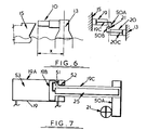
- FIG. 6 when actuation member 21 moves due to the vessel 15 moving towards the tethering station 13 it abuts arm 50A secured to and laterally extending from rod 19C of piston and cylinder unit 19. When member 21 moves away from station 13 it abuts arm 50B secured to and laterally extending from rod 20C of piston and cylinder unit 20.
- Fig. 7 shows unit 19 of Fig. 6 in greater detail from which it will be seen that the working fluid is provided in chamber 51 located between the piston 19B and the cylinder back wall 52 and as previously the piston and rod 19C are hollowed out to provide air bank 25. Similarly chamber 53 located between the piston and the cylinder head is flooded with liquid lubricant.
- thepresent invention is particularly concerned with mooring booms of relatively massive construction capable of restraining the force magnitudes imposed by sea-going vessels such as large oil tankers.
- the restoring forces generated by the piston and cylinder units described above may be of the order of several thousand tonnes and the required dimensions of the ram arrangement is of the order of several tens of meters in length and several meters in diameter.
- the piston of each unit may have a stroke of the order of 5 to 10 meters and a diameter of the order of 1 or 2 meters.
Landscapes
- Engineering & Computer Science (AREA)
- Mechanical Engineering (AREA)
- General Engineering & Computer Science (AREA)
- Chemical & Material Sciences (AREA)
- Combustion & Propulsion (AREA)
- Ocean & Marine Engineering (AREA)
- Physics & Mathematics (AREA)
- Acoustics & Sound (AREA)
- Aviation & Aerospace Engineering (AREA)
- Actuator (AREA)
- Jib Cranes (AREA)
- Toys (AREA)
Applications Claiming Priority (2)
| Application Number | Priority Date | Filing Date | Title |
|---|---|---|---|
| GB8331219 | 1983-11-23 | ||
| GB838331219A GB8331219D0 (en) | 1983-11-23 | 1983-11-23 | Mooring boom |
Publications (1)
| Publication Number | Publication Date |
|---|---|
| EP0142996A2 true EP0142996A2 (de) | 1985-05-29 |
Family
ID=10552204
Family Applications (1)
| Application Number | Title | Priority Date | Filing Date |
|---|---|---|---|
| EP19840308059 Withdrawn EP0142996A2 (de) | 1983-11-23 | 1984-11-21 | Baum zum Befestigen von Schiffen |
Country Status (4)
| Country | Link |
|---|---|
| EP (1) | EP0142996A2 (de) |
| JP (1) | JPS60135392A (de) |
| GB (1) | GB8331219D0 (de) |
| NO (1) | NO844651L (de) |
Cited By (3)
| Publication number | Priority date | Publication date | Assignee | Title |
|---|---|---|---|---|
| CN111043207A (zh) * | 2019-12-12 | 2020-04-21 | 范小英 | 一种漂流浮标的消除海浪能结构 |
| CN113039120A (zh) * | 2018-11-12 | 2021-06-25 | 西尔斯有限责任公司 | 锚固装置 |
| US12545370B2 (en) | 2018-11-12 | 2026-02-10 | Seares S.R.L. | Anchoring device |
-
1983
- 1983-11-23 GB GB838331219A patent/GB8331219D0/en active Pending
-
1984
- 1984-11-21 EP EP19840308059 patent/EP0142996A2/de not_active Withdrawn
- 1984-11-22 NO NO844651A patent/NO844651L/no unknown
- 1984-11-24 JP JP24856384A patent/JPS60135392A/ja active Pending
Cited By (8)
| Publication number | Priority date | Publication date | Assignee | Title |
|---|---|---|---|---|
| CN113039120A (zh) * | 2018-11-12 | 2021-06-25 | 西尔斯有限责任公司 | 锚固装置 |
| US20220001959A1 (en) * | 2018-11-12 | 2022-01-06 | Seares S.R.L. | Anchoring device |
| US11541966B2 (en) * | 2018-11-12 | 2023-01-03 | Seares S.R.L. | Anchoring device |
| EP3880550B1 (de) * | 2018-11-12 | 2024-08-21 | Seares S.r.l. | Verankerungsvorrichtung |
| AU2019378179B2 (en) * | 2018-11-12 | 2025-12-18 | Seares S.R.L. | Anchoring device |
| US12545370B2 (en) | 2018-11-12 | 2026-02-10 | Seares S.R.L. | Anchoring device |
| CN111043207A (zh) * | 2019-12-12 | 2020-04-21 | 范小英 | 一种漂流浮标的消除海浪能结构 |
| CN111043207B (zh) * | 2019-12-12 | 2021-04-13 | 湖南省池海浮标钓具有限公司 | 一种漂流浮标的消除海浪能结构 |
Also Published As
| Publication number | Publication date |
|---|---|
| NO844651L (no) | 1985-05-24 |
| GB8331219D0 (en) | 1983-12-29 |
| JPS60135392A (ja) | 1985-07-18 |
Similar Documents
| Publication | Publication Date | Title |
|---|---|---|
| EP1428973B1 (de) | Tragbarer Tauschwingungskompensator | |
| US4501219A (en) | Tensioner apparatus with emergency limit means | |
| US7112011B2 (en) | Hydro-pneumatic tensioner with stiffness altering secondary accumulator | |
| CN106364630B (zh) | 一种有缆水下机器人半主动升沉补偿系统 | |
| WO2004067435A1 (en) | System for storing, delivering and recovering energy | |
| US4188787A (en) | Hydraulic control apparatus | |
| US4317524A (en) | Hydraulic cranes | |
| US4638978A (en) | Hydropneumatic cable tensioner | |
| KR950011773A (ko) | 해양 지지 구조물상의 연해 플랫폼용 갑판 설치법 | |
| EP0052130A1 (de) | Bewegungseinrichtung mit kontrollierter abwurfkraft. | |
| US4091897A (en) | Hydraulic counterweight and shock-absorbing system | |
| EP0142996A2 (de) | Baum zum Befestigen von Schiffen | |
| US2747370A (en) | Fluid pressure device | |
| US4540159A (en) | Hydropneumatic cable tensioner | |
| US3643934A (en) | Resilient system with compensating device for variable force exerted thereby | |
| DE2803616A1 (de) | System zur wirksamen kompensation unerwuenschter relativ-bewegungen, vorzugsweise waehrend des versetzens einer last | |
| US2732180A (en) | gratzmuller | |
| EP3152445A1 (de) | Hydraulikzylinder | |
| US4964491A (en) | System for limiting snap load intensity | |
| CN119953501B (zh) | 一种应用于甲板货船货物安全智能屏障防护装置 | |
| EP0341021A2 (de) | Hydraulischer Stossdämpfer | |
| US3570441A (en) | Marine towline shock absorber | |
| EP0133768A1 (de) | Vorrichtung zum Spannen von Seilen | |
| CN109703696A (zh) | 用于rov收放的被动式波浪补偿装置 | |
| GB2188899A (en) | A tensioner for tensioning a traction cable |
Legal Events
| Date | Code | Title | Description |
|---|---|---|---|
| PUAI | Public reference made under article 153(3) epc to a published international application that has entered the european phase |
Free format text: ORIGINAL CODE: 0009012 |
|
| AK | Designated contracting states |
Designated state(s): AT BE CH DE FR GB IT LI LU NL SE |
|
| STAA | Information on the status of an ep patent application or granted ep patent |
Free format text: STATUS: THE APPLICATION HAS BEEN WITHDRAWN |
|
| 18W | Application withdrawn |
Withdrawal date: 19860114 |
|
| RIN1 | Information on inventor provided before grant (corrected) |
Inventor name: MCCANN, JAMES Inventor name: WILSON, PETER MURRAY |