EP0143009B1 - Amphibisches Fahrzeug verwendbar als eine selbständige Fähre und als eine Schwimmbrücke - Google Patents
Amphibisches Fahrzeug verwendbar als eine selbständige Fähre und als eine Schwimmbrücke Download PDFInfo
- Publication number
- EP0143009B1 EP0143009B1 EP84401651A EP84401651A EP0143009B1 EP 0143009 B1 EP0143009 B1 EP 0143009B1 EP 84401651 A EP84401651 A EP 84401651A EP 84401651 A EP84401651 A EP 84401651A EP 0143009 B1 EP0143009 B1 EP 0143009B1
- Authority
- EP
- European Patent Office
- Prior art keywords
- hull
- floats
- ramp
- float
- lateral
- Prior art date
- Legal status (The legal status is an assumption and is not a legal conclusion. Google has not performed a legal analysis and makes no representation as to the accuracy of the status listed.)
- Expired
Links
Images


Classifications
-
- B—PERFORMING OPERATIONS; TRANSPORTING
- B60—VEHICLES IN GENERAL
- B60F—VEHICLES FOR USE BOTH ON RAIL AND ON ROAD; VEHICLES CAPABLE OF TRAVELLING IN OR ON DIFFERENT MEDIA, e.g. AMPHIBIOUS VEHICLES
- B60F3/00—Amphibious vehicles, i.e. vehicles capable of travelling both on land and on water; Land vehicles capable of travelling under water
- B60F3/0061—Amphibious vehicles specially adapted for particular purposes or of a particular type
-
- E—FIXED CONSTRUCTIONS
- E01—CONSTRUCTION OF ROADS, RAILWAYS, OR BRIDGES
- E01D—CONSTRUCTION OF BRIDGES, ELEVATED ROADWAYS OR VIADUCTS; ASSEMBLY OF BRIDGES
- E01D15/00—Movable or portable bridges; Floating bridges
- E01D15/14—Floating bridges, e.g. pontoon bridges
- E01D15/22—Floating bridges, e.g. pontoon bridges designed as, or mounted on, vehicles
-
- B—PERFORMING OPERATIONS; TRANSPORTING
- B63—SHIPS OR OTHER WATERBORNE VESSELS; RELATED EQUIPMENT
- B63B—SHIPS OR OTHER WATERBORNE VESSELS; EQUIPMENT FOR SHIPPING
- B63B35/00—Vessels or similar floating structures specially adapted for specific purposes and not otherwise provided for
- B63B35/08—Ice-breakers or other vessels or floating structures for operation in ice-infested waters; Ice-breakers, or other vessels or floating structures having equipment specially adapted therefor
- B63B35/086—Vessels for displacing icebergs, or related methods
Definitions
- the present invention relates to an amphibious vehicle, and more especially a vehicle which can serve as an autonomous ferry for crossing bodies of water or which, assembled with other vehicles of the same type is capable of forming a floating bridge.
- This vehicle is more specifically, although not exclusively, intended to allow the crossing of bodies of water or watercourses to military vehicles and to troops in the event of armed conflicts.
- the inflatable auxiliary floats have a length less than that of the hull so that it remains between each end of each of them and the adjacent one of a possible neighboring float carried by one of the ramps of the vehicle in question , an interval into which water can rush in and which therefore affects the stability of the vehicle.
- this type of vehicle generally comprises, aquatic propulsion means constituted by adjustable propellers and mounted on telescopic supports vertically disposed at its front walls.
- aquatic propulsion means constituted by adjustable propellers and mounted on telescopic supports vertically disposed at its front walls.
- the presence of these propellers requires, for their proper functioning, the fitting of niches and tunnels in the hull, as well as the fitting out of spaces between the hull and the floats.
- each lateral float associated with the hull has, in the inflated position, a length corresponding to the length of the hull, while articulated flaps, integral with the floats, and occupying a horizontal position extending the upper wall of the hull in the inflated position of the floats, each have a length slightly less than that of the hull, so as to release the end portholes formed in the side walls, in the folded position of the flaps, the ends of each fleet ur comprising an elastic return system between the shell and the corresponding flap, in the deflated position and on
- each lateral float associated with a ramp has a width substantially equal to that of the lateral floats associated with the hull
- each flap associated with a lateral ramp float has a width substantially equal to that of a flap associated with a float of shell, and is made in two parts articulated around a longitudinal axis.
- This last characteristic is very interesting because it allows, despite a relatively low height of the ramp elements, to fold along these flaps which have a total width equal to that of the flaps articulated on the hull.
- each ramp section articulated at one end of the hull, is equipped with an inflatable float which, occupying a central position and extending between the longitudinal floats, comes to bear against the front wall of the hull, and is maintained in position by a flap, arranged under the ramp and articulated on it around an axis parallel to the axis of articulation of the ramp of the hull.
- This transverse flap fulfills the same functions as the flaps associated with the longitudinal floats allowing the central compartment to be in contact with the hull without undergoing vertical deformations under the hydrostatic thrust.
- this articulated flap fulfills a function of tie rod between the two elements of the ramp folded by hydraulic or mechanical locking. In this way, the ramp fulfills its functions of homogeneous and undeformable span, during tensioning under rolling loads, when the vehicle forms a bridge element.
- the various floats are fitted with safety valves calibrated to a determined value and are supplied with pressurized air by groups of compressor-decompressors with continuous flow.
- This arrangement is interesting because it allows a permanent supply of all the compartments of the floats ensuring compensation for permanent leaks by the safety valves, or accidental by tearing for example.
- This permanent injection of air ensures a flexible and continuous connection of the various floats during the various movements of which the vehicle is susceptible, while the presence of safety valves avoids the harmful overpressures likely to occur during the maneuvering of the ramps, by example during a negative site docking period.
- the compressor groups are arranged to operate as decompressors by reversing their direction of rotation, and are connected to the various compartments of the inflatable floats by means of double-acting valves associated with means controlling their opening as soon as the group works in decompression.
- double-acting valves associated with means controlling their opening as soon as the group works in decompression.
- compressor-decompressor groups are provided, one for each lateral hull float and one in each ramp.
- each float is compartmentalized by conical partitions, the ends of which bear against one another. This arrangement allows, in the event of a tearing of a compartment, the occupation for part of it by the ends of the neighboring compartments, which avoids significantly reducing the bearing characteristics of the machine.
- the means ensuring the movement of the vehicle on the water consist of propellants with pressurized water jets disposed near the two front walls of the hull.
- each propellant has a vertically suction point for the water, bringing the latter to a horizontal helicoid ensuring the compression of the fluid and then projecting the propellant jet tangentially to the helicoid at an angle of the order of 15 ° under the shell.
- the equipment of the machine in horizontal thrusters instead of vertical telescopic propellers, as currently used, allows to deeply modify the structures of the ends of the hull by eliminating all the water supply tunnels to the propellers and the evacuation of the pulsed flow, and to adapt these profiles to include the thrusters, so that these are protected during landings and landings in shallow water, while respecting the approach and exit angles compatible with all-terrain circulation of the craft. It is thus possible to increase the height of the front end panels of the hull and to provide in them the access doors to the cockpits, facilitating the entry and exit of the crew, even when the he craft is afloat, the ramps being folded over the hull, thus making it possible to rescue the driver in the event of distress of the craft in this navigation configuration.
- the elimination of the necessary tunnels in the case of propellers makes it possible to lower the cockpit floor to the level of the bottom of the hull stiffeners, which improves the habitability and, consequently, the comfort of the crews while allowing the installation of new driving equipment.
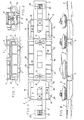
- the vehicle shown in the drawing comprises a central part constituted by a shell (2) of generally parallelepiped shape. This hull is fitted with motorized and retractable wheels (3), allowing the vehicle to travel on land.
- two ramps (5) are articulated, each of which comprises a first part (6) articulated directly on the hull (2) and a second part ( 7) articulated only on the ramp section (6).
- two propulsion units each of which comprises a vertical suction zone for the water bringing the latter to a helix ensuring the compression of the fluid, then projecting the propellant jet onto the hull with an angle of about 15 °.
- the front panels of the hull are practically vertical over their entire height, allowing the provision in these of doors (10) for access to the cabins.
- the lateral vision from the cabs forming the cockpit is ensured by means of fixed portholes (12) formed in the side walls, near the ends of the latter.
- the hull (2) of the vehicle is equipped along its two longitudinal walls with two inflatable longitudinal floats (13).
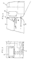
- Each float (13) is associated with a flap (14) which, of length slightly less than that of the hull so as to release the portholes (12) in the position of movement on the road, is arranged vertically along a longitudinal wall of the hull and covers the corresponding float (13), as shown in particular on the left-hand side of FIG. 7, and which, in the navigation position, occupies a horizontal position in the extension of the upper wall of the hull and prevents deformation vertical to the top of the corresponding float, under the effect of hydrostatic pressure.
- the flaps (14) are actuated using hydraulic cylinders (15), while the floats (13) fold back into the closed position under the action of elastic return straps.
- Each section (6) of a ramp (5) is equipped, for its part, with two lateral and longitudinal floats (16), each of which has a length substantially corresponding to that of the section of ramp considered, so as to come into abutment against the hull float (13) located on the same side.
- each of these is associated with a flap (17) produced in two parts, respectively (18) and (19), articulated around a longitudinal axis ( 20).
- the part (18) is actuated by hydraulic cylinders (22), while the part (19) folds automatically under the effect of the elastic return of the floats (16) in the deflated position.
- This arrangement makes it possible to have floats lateral ramps, of large section, without the flaps (17) of support thereof forming an annoying widening of the vehicle during the period of overland travel thereof.
- Each section (6) of ramp (5) is also equipped with a central float (23) which, disposed between the two lateral floats (16), comes, in the inflated position, to bear against the front wall (4) of the shell.
- This central float (23) is associated a flap (24) which, articulated on the ramp (6), and foldable along the latter in the deflated position of the float, serves as a vertical support for the upper part thereof. ci, in the area between the ramp section (6) considered and the front wall of the hull (2).
- the central float (23) and the two lateral floats (16) are housed in the same envelope (21), thus providing a one-piece assembly ensuring good continuity of the water lines.
- each float As shown in the drawing, air is supplied to the various compartments of each float from a compressor-decompressor group, by means of a double-acting valve (25), each compartment also comprising a pressure relief valve. discharge (26) tared at a value of the order of 0.2 x 10 5 Pa. It is thus possible to ensure a constant pressure inside the floats, despite the different movements of the vehicle likely to occur during the period navigation, and despite possible leaks that may be due to tears.
- the vehicle anchors (27) are housed in the sections of end ramps (7) closed by removable flaps (28).
- the invention brings a great improvement to the existing technique by providing an amphibious vehicle which, in particular because of its mode of aquatic propulsion, has very many advantages compared to existing vehicles.
- the capacity of movement of the vehicle in water is improved due to the size of the surface of the floats which, made of a synthetic material, have a better coefficient of slip than the hull which is, for its hand, made of metal.
Landscapes
- Engineering & Computer Science (AREA)
- Architecture (AREA)
- Civil Engineering (AREA)
- Structural Engineering (AREA)
- Chemical & Material Sciences (AREA)
- Combustion & Propulsion (AREA)
- Transportation (AREA)
- Mechanical Engineering (AREA)
- Body Structure For Vehicles (AREA)
- Bridges Or Land Bridges (AREA)
- Vehicle Step Arrangements And Article Storage (AREA)
Claims (9)
Priority Applications (1)
| Application Number | Priority Date | Filing Date | Title |
|---|---|---|---|
| AT84401651T ATE26140T1 (de) | 1983-09-19 | 1984-08-08 | Amphibisches fahrzeug verwendbar als eine selbstaendige faehre und als eine schwimmbruecke. |
Applications Claiming Priority (2)
| Application Number | Priority Date | Filing Date | Title |
|---|---|---|---|
| FR8314859 | 1983-09-19 | ||
| FR8314859A FR2552031B1 (fr) | 1983-09-19 | 1983-09-19 | Vehicule amphibie pouvant servir de bac autonome et pouvant former un pont flottant |
Publications (2)
| Publication Number | Publication Date |
|---|---|
| EP0143009A1 EP0143009A1 (de) | 1985-05-29 |
| EP0143009B1 true EP0143009B1 (de) | 1987-03-25 |
Family
ID=9292319
Family Applications (1)
| Application Number | Title | Priority Date | Filing Date |
|---|---|---|---|
| EP84401651A Expired EP0143009B1 (de) | 1983-09-19 | 1984-08-08 | Amphibisches Fahrzeug verwendbar als eine selbständige Fähre und als eine Schwimmbrücke |
Country Status (5)
| Country | Link |
|---|---|
| US (1) | US4621385A (de) |
| EP (1) | EP0143009B1 (de) |
| AT (1) | ATE26140T1 (de) |
| DE (1) | DE3462809D1 (de) |
| FR (1) | FR2552031B1 (de) |
Families Citing this family (20)
| Publication number | Priority date | Publication date | Assignee | Title |
|---|---|---|---|---|
| FI91429C (fi) * | 1988-04-11 | 1994-06-27 | Esko Poentynen | Tie- tai lentokenttärakenne |
| US5018630A (en) * | 1988-11-21 | 1991-05-28 | Mcghie James R | High-capacity lift crane assembly |
| FR2649426B1 (fr) * | 1989-07-06 | 1992-03-20 | Mediterranee Const Navales Ind | Systeme de pontage permettant a des vehicules de franchir des breches |
| IT1254155B (it) * | 1991-03-20 | 1995-09-11 | Giovanni Miglietti | Ponte girevole per autopropulsione. |
| FR2680144A1 (fr) * | 1991-08-05 | 1993-02-12 | Arifon Philippe | Structure de concept polyvalent, tractable, insubmersible ou submersible, de dimensions modifiables pouvant s'adapter a des terrains tres divers. |
| GB2287910A (en) * | 1994-03-28 | 1995-10-04 | William Mctaggart | An amphibious vehicle |
| DE19746293A1 (de) * | 1997-10-20 | 1999-04-22 | Krupp Foerdertechnik Gmbh | Schwimmbrücke oder Fähre |
| US6000358A (en) * | 1998-05-14 | 1999-12-14 | Dickenson; Robert P. | Beaching bow for floating platforms and watercraft |
| CA2354229A1 (en) | 2000-07-28 | 2002-01-28 | Donald R. Redman | Amphibious vehicle having an inflatable pontoon |
| US6502523B1 (en) * | 2000-11-27 | 2003-01-07 | Gary K. Robb | Road-towed heavy ferry |
| US7021228B2 (en) * | 2000-11-27 | 2006-04-04 | Robb Gary K | Road towed ferry |
| ATE311301T1 (de) * | 2002-01-30 | 2005-12-15 | Gen Dynamics Santa Barbara Sis | Amphibisches brücken- und übersetzfahrzeug |
| US6651578B1 (en) | 2002-03-27 | 2003-11-25 | Patrick Henry Gorman | Floating structures |
| RU2272740C1 (ru) * | 2004-08-12 | 2006-03-27 | Виктор Николаевич Треножкин | Понтон для транспортного средства |
| FR2889213B1 (fr) * | 2005-07-27 | 2007-09-07 | Mediterranee Const Ind | Systeme de transport d'une travure par un vehicule routier pouvant etre transforme en vehicule amphibie pour permettre a tout vehicule routier de franchir une breche seche ou remplie d'eau |
| GB0523226D0 (en) * | 2005-11-15 | 2005-12-21 | Ardern Fergus J | Bridging system |
| EP2650205A1 (de) * | 2012-04-13 | 2013-10-16 | Schmidt, Frédéric | Modul für die Herstellung eines Roll-On/Roll-off-Amphibiengeräts |
| NO337411B1 (no) * | 2013-11-20 | 2016-04-11 | Cruise Ventures As | Et nytt konsept for ilandføring av personell og materiell fra skip |
| US10731305B2 (en) * | 2017-11-01 | 2020-08-04 | Dinh Chinh Nguyen | Fast installing self-propelled pontoon bridge |
| CN110497750A (zh) * | 2019-07-02 | 2019-11-26 | 刘璐 | 一种两栖多用途高速渡船 |
Family Cites Families (12)
| Publication number | Priority date | Publication date | Assignee | Title |
|---|---|---|---|---|
| US2403436A (en) * | 1941-09-30 | 1946-07-09 | Specialties Dev Corp | Inflation device |
| US2321677A (en) * | 1942-02-24 | 1943-06-15 | Higgins Andrew Jackson | Amphibian bridge |
| US2981221A (en) * | 1956-06-04 | 1961-04-25 | Hermann Walter Gehlen Dipl Ing | Self propelled amphibious vehicles |
| DE1556958B1 (de) * | 1964-03-28 | 1969-12-11 | Gehlen Dipl Ing Dr Rer Pol Her | Amphibienfahrzeug |
| US3543713A (en) * | 1967-11-24 | 1970-12-01 | White & Co Ltd Samuel | Propulsion unit for a vessel |
| DE1556451B2 (de) * | 1968-02-27 | 1971-12-16 | Gehlen, Hermann Walter, Dipl.-Ing. Dr.Rer.Pol., 6750 Kaiserslautern | Amphibienfahrzeug zum einsatz als brueckenfahrzeug |
| FR2013032A1 (de) * | 1968-07-16 | 1970-03-27 | Mambretti Riccardo | |
| FR2271117A1 (en) * | 1974-05-17 | 1975-12-12 | France Etat | Inflatable buoyancy bags for amphibious vehicle - are mounted under hinged flaps on sides of vehicle and raised by rams |
| FR2358314A1 (fr) * | 1976-07-16 | 1978-02-10 | Pronal Sa | Engin utilisable notamment comme vehicule amphibie |
| US4145786A (en) * | 1978-02-27 | 1979-03-27 | Myers James S | Portable floating apparatus |
| US4328601A (en) * | 1979-12-26 | 1982-05-11 | Fmc Corporation | Inflatable bow |
| FR2500504B1 (fr) * | 1981-02-20 | 1985-12-27 | Goeppner Kaiserslautern Eisen | Pont flottant motorise |
-
1983
- 1983-09-19 FR FR8314859A patent/FR2552031B1/fr not_active Expired
-
1984
- 1984-08-08 EP EP84401651A patent/EP0143009B1/de not_active Expired
- 1984-08-08 DE DE8484401651T patent/DE3462809D1/de not_active Expired
- 1984-08-08 AT AT84401651T patent/ATE26140T1/de not_active IP Right Cessation
- 1984-09-04 US US06/646,927 patent/US4621385A/en not_active Expired - Lifetime
Also Published As
| Publication number | Publication date |
|---|---|
| EP0143009A1 (de) | 1985-05-29 |
| FR2552031B1 (fr) | 1987-04-10 |
| US4621385A (en) | 1986-11-11 |
| ATE26140T1 (de) | 1987-04-15 |
| FR2552031A1 (fr) | 1985-03-22 |
| DE3462809D1 (en) | 1987-04-30 |
Similar Documents
| Publication | Publication Date | Title |
|---|---|---|
| EP0143009B1 (de) | Amphibisches Fahrzeug verwendbar als eine selbständige Fähre und als eine Schwimmbrücke | |
| US4522143A (en) | Folding boat with bow and stern sections | |
| FR2499934A1 (fr) | Engin nautique flottant et insubmersible | |
| EP0165192A1 (de) | Halbabsinkbares Wasserfahrzeug | |
| EP3936383B1 (de) | Modulierbares deckenbett für ausgestatteten kastenwagen | |
| EP0527897B1 (de) | Mehrrumpf wasserfahrzeug | |
| CA2354229A1 (en) | Amphibious vehicle having an inflatable pontoon | |
| FR2463049A1 (fr) | Engin nautique flottant et insubmersible | |
| ES2323734T3 (es) | Sistema de transporte de una viga de tramo sobre un vehiculo de carretera que se puede transformar en vehiculo anfibio para permitir que cualquier vehiculo de carretera atraviese un tajo seco o lleno de agua. | |
| EP2836421B1 (de) | Modul für die herstellung einer roll-on/roll-off-schwimmbrücke | |
| FR2950567A1 (fr) | Vehicule amphibie | |
| LU84437A1 (fr) | Vehicule amphibie a deux roues | |
| FR2538773A1 (fr) | Canot pneumatique semi-rigide | |
| EP1910161B1 (de) | Hochgeschwindigkeits-mehrrumpfboot | |
| FR2756809A1 (fr) | Radeau de sauvetage de grande capacite | |
| EP0014830A1 (de) | Motorisierter schwimmender Ponton für einen aufsetzbaren Wohnwagen | |
| US11772439B2 (en) | Amphibious vehicle with retractable floaters | |
| FR2576868A1 (fr) | Navire transbordeur pour le transport de vehicules et de passagers | |
| CA3113512C (en) | Amphibious vehicle with retractable floaters | |
| EP0241620B1 (de) | Rumpfform für ein Bodeneffektschiff mit Seitenkielen für zwei Fahrweisen | |
| FR2615476A1 (fr) | Bateau de sauvetage insubmersible, a vidage automatique, comportant un poste integre pour un brancard | |
| FR2546124A1 (fr) | Canot pneumatique semi-rigide | |
| EP1900626A1 (de) | Schwimmeranordnung eines Schlauchboots mit starrem Rumpf und damit ausgestattetes Boot | |
| FR2680747A1 (fr) | Structure a usages multiples pour bateau. | |
| FR2523044A1 (fr) | Habitacle du type caravane transformable en bateau |
Legal Events
| Date | Code | Title | Description |
|---|---|---|---|
| PUAI | Public reference made under article 153(3) epc to a published international application that has entered the european phase |
Free format text: ORIGINAL CODE: 0009012 |
|
| AK | Designated contracting states |
Designated state(s): AT BE CH DE FR GB IT LI LU NL SE |
|
| 17P | Request for examination filed |
Effective date: 19850709 |
|
| 17Q | First examination report despatched |
Effective date: 19860326 |
|
| GRAA | (expected) grant |
Free format text: ORIGINAL CODE: 0009210 |
|
| AK | Designated contracting states |
Kind code of ref document: B1 Designated state(s): AT BE CH DE FR GB IT LI LU NL SE |
|
| REF | Corresponds to: |
Ref document number: 26140 Country of ref document: AT Date of ref document: 19870415 Kind code of ref document: T |
|
| ITF | It: translation for a ep patent filed | ||
| REF | Corresponds to: |
Ref document number: 3462809 Country of ref document: DE Date of ref document: 19870430 |
|
| PLBE | No opposition filed within time limit |
Free format text: ORIGINAL CODE: 0009261 |
|
| STAA | Information on the status of an ep patent application or granted ep patent |
Free format text: STATUS: NO OPPOSITION FILED WITHIN TIME LIMIT |
|
| 26N | No opposition filed | ||
| ITTA | It: last paid annual fee | ||
| EPTA | Lu: last paid annual fee | ||
| EAL | Se: european patent in force in sweden |
Ref document number: 84401651.9 |
|
| PGFP | Annual fee paid to national office [announced via postgrant information from national office to epo] |
Ref country code: AT Payment date: 20010803 Year of fee payment: 18 |
|
| PGFP | Annual fee paid to national office [announced via postgrant information from national office to epo] |
Ref country code: SE Payment date: 20010806 Year of fee payment: 18 Ref country code: DE Payment date: 20010806 Year of fee payment: 18 |
|
| PGFP | Annual fee paid to national office [announced via postgrant information from national office to epo] |
Ref country code: GB Payment date: 20010808 Year of fee payment: 18 Ref country code: BE Payment date: 20010808 Year of fee payment: 18 |
|
| PGFP | Annual fee paid to national office [announced via postgrant information from national office to epo] |
Ref country code: LU Payment date: 20010827 Year of fee payment: 18 |
|
| PGFP | Annual fee paid to national office [announced via postgrant information from national office to epo] |
Ref country code: NL Payment date: 20010831 Year of fee payment: 18 |
|
| PGFP | Annual fee paid to national office [announced via postgrant information from national office to epo] |
Ref country code: CH Payment date: 20011101 Year of fee payment: 18 |
|
| REG | Reference to a national code |
Ref country code: GB Ref legal event code: IF02 |
|
| PG25 | Lapsed in a contracting state [announced via postgrant information from national office to epo] |
Ref country code: LU Free format text: LAPSE BECAUSE OF NON-PAYMENT OF DUE FEES Effective date: 20020808 Ref country code: GB Free format text: LAPSE BECAUSE OF NON-PAYMENT OF DUE FEES Effective date: 20020808 Ref country code: AT Free format text: LAPSE BECAUSE OF NON-PAYMENT OF DUE FEES Effective date: 20020808 |
|
| PG25 | Lapsed in a contracting state [announced via postgrant information from national office to epo] |
Ref country code: SE Free format text: LAPSE BECAUSE OF NON-PAYMENT OF DUE FEES Effective date: 20020809 |
|
| PG25 | Lapsed in a contracting state [announced via postgrant information from national office to epo] |
Ref country code: LI Free format text: LAPSE BECAUSE OF NON-PAYMENT OF DUE FEES Effective date: 20020831 Ref country code: CH Free format text: LAPSE BECAUSE OF NON-PAYMENT OF DUE FEES Effective date: 20020831 Ref country code: BE Free format text: LAPSE BECAUSE OF NON-PAYMENT OF DUE FEES Effective date: 20020831 |
|
| BERE | Be: lapsed |
Owner name: CHAUDRONNERIE ET FORGES D'ALSACE *C.E.F.A. Effective date: 20020831 |
|
| PG25 | Lapsed in a contracting state [announced via postgrant information from national office to epo] |
Ref country code: NL Free format text: LAPSE BECAUSE OF NON-PAYMENT OF DUE FEES Effective date: 20030301 Ref country code: DE Free format text: LAPSE BECAUSE OF NON-PAYMENT OF DUE FEES Effective date: 20030301 |
|
| EUG | Se: european patent has lapsed | ||
| GBPC | Gb: european patent ceased through non-payment of renewal fee |
Effective date: 20020808 |
|
| REG | Reference to a national code |
Ref country code: CH Ref legal event code: PL |
|
| NLV4 | Nl: lapsed or anulled due to non-payment of the annual fee |
Effective date: 20030301 |
|
| PGFP | Annual fee paid to national office [announced via postgrant information from national office to epo] |
Ref country code: FR Payment date: 20030710 Year of fee payment: 20 |