EP0143057A2 - Entladevorrichtung insbesondere für Behälter mit rundem Boden - Google Patents
Entladevorrichtung insbesondere für Behälter mit rundem Boden Download PDFInfo
- Publication number
- EP0143057A2 EP0143057A2 EP84402376A EP84402376A EP0143057A2 EP 0143057 A2 EP0143057 A2 EP 0143057A2 EP 84402376 A EP84402376 A EP 84402376A EP 84402376 A EP84402376 A EP 84402376A EP 0143057 A2 EP0143057 A2 EP 0143057A2
- Authority
- EP
- European Patent Office
- Prior art keywords
- screw
- motor
- silo
- central
- integral
- Prior art date
- Legal status (The legal status is an assumption and is not a legal conclusion. Google has not performed a legal analysis and makes no representation as to the accuracy of the status listed.)
- Granted
Links
Images



Classifications
-
- B—PERFORMING OPERATIONS; TRANSPORTING
- B65—CONVEYING; PACKING; STORING; HANDLING THIN OR FILAMENTARY MATERIAL
- B65G—TRANSPORT OR STORAGE DEVICES, e.g. CONVEYORS FOR LOADING OR TIPPING, SHOP CONVEYOR SYSTEMS OR PNEUMATIC TUBE CONVEYORS
- B65G65/00—Loading or unloading
- B65G65/30—Methods or devices for filling or emptying bunkers, hoppers, tanks, or like containers, of interest apart from their use in particular chemical or physical processes or their application in particular machines, e.g. not covered by a single other subclass
- B65G65/34—Emptying devices
- B65G65/40—Devices for emptying otherwise than from the top
- B65G65/46—Devices for emptying otherwise than from the top using screw conveyors
- B65G65/466—Devices for emptying otherwise than from the top using screw conveyors arranged to be movable
Definitions
- the present invention relates to an extraction device using an endless screw driven in a sweeping movement along an angular path of 360 ° and making it possible to cover the circular base of a silo containing a loose material, for example grainy or powdery.
- the worm drive motor is positioned directly above the discharge funnel and the screw motor is sheltered by an upper protective cone on which the bulk material rests.
- the invention relates to an extraction device for silos with a circular base and discharge from an opening in the form of a central funnel and taken up by a conveyor in the lower position relative to the floor of the silo, of the type comprising a worm driven by a motor in a substantially central position and capable of angularly sweeping the base of the pile close to the floor by bringing the product towards the discharge funnel, and the device is characterized in that it comprises a central pivot fixed resting on a lower fulcrum coming from the fixed structure of the silo and this pivot supports a protective cover of generally conical shape fixed and integral with said pivot, said cover, substantially concentric with the central pivot, being able to house said motor drive of the screw and the orifice constituting the discharge funnel.
- the assembly constituted by the screw and its motorization is mounted integral with a rotating structure in the form of a crown and rotatably mounted on a fixed crown integral with the fixed structure of the silo, the rotating crown, integral with the assembly live and motorization, being able to undergo the action of a drive member such as a pinion or roller coming from a second motor capable of rotating the assembly constituted by the rotating structure carrying the screw and its motorization, in its horizontal angular scanning movement of the bottom of the silo.
- a drive member such as a pinion or roller coming from a second motor capable of rotating the assembly constituted by the rotating structure carrying the screw and its motorization, in its horizontal angular scanning movement of the bottom of the silo.
- the rotating structure consists of a protective casing of generally cylindrical shape, substantially concentric with the central pivot and provided with an opening on its wall for the passage of the screw and of the material entrained by it towards the central discharge funnel, the cylindrical casing being integral with a crown, such as a toothed crown, receiving the action of a drive pinion from the second motor and thus capable of causing the rotation of the cylindrical carrier casing of the screw and motorization assembly.
- the fixed crown is mounted integral with the lower edges of the cover or protective cone and the rotating structure is thus rotatably mounted, being suspended by means of a bearing such as a ball bearing, at lower edge of said protective cover, the second drive motor of the rotating structure being mounted integral with the wall of this cover.
- the fixed crown is mounted integral with the slab constituting the floor of the silo and it substantially surrounds the periphery of the discharge orifice or funnel, the rotating structure carrying the screw and motorization assembly thus rests on the fixed crown on which it is rotatably mounted by means of rolling means, such as ball bearings or rollers, and the second drive motor of the rotating structure is integral with the slab, being mounted on the internal wall of the orifice or discharge funnel.
- the protective cover or cone resting on the central pivot is itself secured to a radial beam joining the wall of the silo, said beam being provided with an inverted V section.
- the radial beam with inverted V section is provided with a dimension allowing it to constitute a member for protecting the extraction screw in the rest position and it internally contains the second motor driving the rotating structure carrying the 'screw and motorization assembly.
- the beam prefferably house at least one coolant conduit opening on one side to the outside and accessing the zone constituted by the space arranged in line with the protective cone, this conduit allowing the evacuation of calories released by the worm drive motor and the second motor driving the rotating structure.
- the screw can be powered by an electric motor connected to the supply circuit by rotary contacts mounted on the fixed pivot.
- the central pivot carrying the cover or protective cone itself is constituted by a hollow cylindrical axis and it internally contains the supply circuits respectively of the drive motor of the worm and the second motor causing the rotation of the rotating structure, the cylindrical pivot being provided with members allowing the connection between said fixed circuits and the rotary connections joining the screw drive motor, such as conctacts or rotary joints.
- the central pivot is connected to the walls of the funnel or discharge orifice by means of crosspieces mounted at right angles and forming a cross-piece whose ends are sealed in the thickness of the slab forming the floor. from the silo.
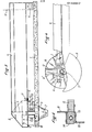
- a central pivot or vertical shaft 5 rests on a cross 6 anchored at the top of the central evacuation funnel 7.
- the cross 6 allows a firm anchoring of the central pivot 5. But the pivot could be erected from the infrastructure without pressing on the walls of the funnel.
- the pivot 5 is secured, in a manner known per se, to a protective cover or cone 8, and this cone is itself held firmly by the radial beam 9.
- This beam 9 is, in a manner known per se, provided with a profile in the form of an inverted V consequently allowing the flow of the material on either side of the radial beam. It joins the peripheral wall 10 of the silo and it is anchored at its outer end on a cement base 11.
- central pivot 5 is held at its base and at its top, which provides it with a firm positioning and anchoring allowing it to resist the forces and stresses of the movement of the screw both in its rotation along its axis for training. of the material only in its horizontal scanning movement traversing; angularly the base of the silo flush with the floor 1.
- the screw and motorization assembly is positioned tangentially with respect to the fixed central pivot 5, the tangential axis of the motorized screw itself being driven in its horizontal scanning movement around the central axis occupied by the pivot 5.
- the screw assembly 2 and its motorization 4 in the example produced is mounted integral with a rotating cylindrical casing 18, by means of the crosspieces 12, 12 '.
- the cylindrical casing 18 is integral at its top with the external toothed crown 13 mounted, by means of a roller bearing, on a fixed concentric crown 14, itself integral with the fixed structure constituted by the base of the cover conical 8.
- a drive member for example a pinion 15 driven by an electric motorization unit 16 or hydraulic 17.
- the pinion 15 causes the rotation of the ring gear 13 which consequently causes the rotation along a horizontal plane of the assembly of the rotating structure formed by the cylindrical casing 18 supporting the screw 2 and its motorization thus ensuring the angular sweeping, along the vertical axis of the pivot 5, of the base of the silo at the level of the floor 1, this movement being accompanied by the rotation of the screw on itself driven by its electric motorization 3 or hydraulic 4.
- the beam also houses the pipes bringing the driving force from the outside to the motorization system of the screw and made up either of electric cables joining the motor 3 via rotary contacts 6; in the context of the use of a hydraulic motor unit 4 ( Figures 3 and 4), the passage between the motor 4 rotating around the axis 5 and the supply and fixed return of hydraulic fluid can be obtained from conventionally by the use of rotary joints.
- FIGS. 7 and 6 relate to an alternative embodiment in which the protective cone 8 ′ which is here in the form of a cover with a bottom of a generally parabolic profile extended by cylindrical edges, is mounted on the fixed central pivot 5 ′ of which it is integral, without being otherwise connected to the wall of the silo by a beam as in the previous examples.
- the screw 2 ' is powered by a hydraulic motor 4' mounted in a rotating structure constituted by the cylindrical casing 18 'to which the motor 4' is connected by crosspieces 12,12 'joining two diametrically opposite edges of the cylinder 18; it will be noted that in Figure 7 we distinguish the two upper and lower halves of the figure; the plan view of the figure corresponds to a horizontal section taken along the line VII-VII of Figure 6; while the sectional view of FIG. 6 represents a vertical section along the line VI-VI of FIG. 7.
- the supply lines 21 and 21 ′ corresponding for example to the arrival and return of the hydraulic fluid, pass through the silo infrastructure and open into the internal pipes at the pivot 5 ′ and constituted by the sheath 21 ′ and the space 22 'within the cylindrical pivot 5'; beyond the rotary joint 20, the hoses 23 and 24 join the motor 4 '.
- the cylinder 18 ′ constituting the rotary casing carrying the screw 2 ′ and motorization 4 ′ assembly is here in rotary support on a lower bearing.
- the toothed ring 25 is mounted at the base of the cylinder 18 'via the ring 25 and it is rotatably mounted on the fixed outer ring 26, for example by means of a bearing or ball bearing or with known type of rollers.
- the fixed crown is positioned in the peripheral position relative to the edge of the funnel 7 'and it is integral with the slab constituting the floor of the silo.
- the movable ring 25, supporting the rotating cylindrical casing 18 ' can be driven in rotation by the pinion 15', itself driven from the motor 17 'which can be a hydraulic motor; and as the motor 17' is fixed, it can be supplied by fixed pipes (not shown).
- the motor 17 'thus rotates the roller 15' which causes the rotary movement of the structure constituted by the cylindrical casing 18 'carrying the screw assembly 2' and the motorization 4 'and thus causing the sweeping movement of the silo base by bringing back the granular or pulverulent matters entrained by the screw 2 'towards the center and their evacuation by the funnel 7'.
- the cylinder 18 ' has a passage or opening 27 in its wall to allow the rotation of the screw 2' and the centripetal drive of the materials.
- central cylindrical pivot 5 'could internally contain pipes conveying the supply currents in the case of an electric motor driving the screw and in this case, the passage from the fixed central pivot 5' to the motor s '' effect by rotating contacts; the central pivot 5 'could also internally contain pipes ensuring the arrival of fresh air flow to cool the motors.
- the pivot 5 rests on the cross made up of the crosspieces 28,28 ', 29,29'.
- FIG. 8 represents a variant in which the central pivot 30 is anchored at its base in the structure which constitutes the base of the silot.
- the pivot 30 is thus firmly held by a set of crosspieces 31, 31 ′ which together form a cross-piece which ensures firm and correct positioning and the anchoring of the central tubular pillar or pivot 30.
- the pillar 30 is effectively erected from its base to the top carrying the protective cone 32 and it is held firmly by its anchoring on the crosspieces 31 and 31 'themselves integral with the walls 33 of the well of 'central evacuation; this avoids cluttering the passage area which allows the evacuation of the products supplied by the screw 34; in this case the materials pass through the opening 35 to pour into the evacuation well defined by the cylindrical wall 33.
- the well defined by the cylinder 33 is itself divided by the central partition 36 into two semi-cylindrical beds 37 and 37 'each served by a screw which conveys the discharged materials from the upper part to outside.
- the circuits serving the hydraulic motor 39 pass, as previously described, inside the central pivot 30 to reach the rotary joint 40.
- the motor 41 provided for driving the casing 42 is disposed in an external position relative to the well 33, which makes it possible to clear the evacuation passage area; in this case, the crown 42 secured to the cylindrical casing 43 and driven by the pinion 44 from the drive motor 41, rests on the inner crown 45 by means of a ball bearing.
Landscapes
- Engineering & Computer Science (AREA)
- Mechanical Engineering (AREA)
- Filling Or Emptying Of Bunkers, Hoppers, And Tanks (AREA)
Priority Applications (1)
| Application Number | Priority Date | Filing Date | Title |
|---|---|---|---|
| AT84402376T ATE44274T1 (de) | 1983-11-22 | 1984-11-21 | Entladevorrichtung insbesondere fuer behaelter mit rundem boden. |
Applications Claiming Priority (2)
| Application Number | Priority Date | Filing Date | Title |
|---|---|---|---|
| FR8318560A FR2555148B1 (fr) | 1983-11-22 | 1983-11-22 | Dispositif d'extraction notamment pour silos a base circulaire |
| FR8318560 | 1983-11-22 |
Publications (3)
| Publication Number | Publication Date |
|---|---|
| EP0143057A2 true EP0143057A2 (de) | 1985-05-29 |
| EP0143057A3 EP0143057A3 (en) | 1986-12-30 |
| EP0143057B1 EP0143057B1 (de) | 1989-06-28 |
Family
ID=9294379
Family Applications (1)
| Application Number | Title | Priority Date | Filing Date |
|---|---|---|---|
| EP84402376A Expired EP0143057B1 (de) | 1983-11-22 | 1984-11-21 | Entladevorrichtung insbesondere für Behälter mit rundem Boden |
Country Status (6)
| Country | Link |
|---|---|
| US (1) | US4655666A (de) |
| EP (1) | EP0143057B1 (de) |
| AT (1) | ATE44274T1 (de) |
| DE (1) | DE3478805D1 (de) |
| FR (1) | FR2555148B1 (de) |
| OA (1) | OA07869A (de) |
Cited By (3)
| Publication number | Priority date | Publication date | Assignee | Title |
|---|---|---|---|---|
| FR2646413A1 (fr) * | 1989-04-28 | 1990-11-02 | Ramboz Maurice | Groupe moto-red ucteur a renvoi d'angle, notamment pour l'extracteur a vis equipant la base d'un silo de stockage |
| FR2686328A1 (fr) * | 1992-01-17 | 1993-07-23 | Starvrac Sa | Dispositif d'extraction de matieres pulverulentes ou granuleuses, notamment depuis un silo circulaire. |
| FR2778394A1 (fr) * | 1998-05-07 | 1999-11-12 | Starvrac | Ensemble extracteur a vis pour matieres solides |
Families Citing this family (23)
| Publication number | Priority date | Publication date | Assignee | Title |
|---|---|---|---|---|
| FR2626262A1 (fr) * | 1988-01-25 | 1989-07-28 | Starvrac | Extracteur pour silo de stockage |
| FR2686076B1 (fr) * | 1992-01-15 | 1994-04-08 | Starvrac Sa | Dispositif pour l'evacuation de matieres granuleuses ou pulverulentes depuis un silo circulaire de stockage. |
| US7127854B2 (en) * | 2003-02-13 | 2006-10-31 | Hedrick Thomas W | Bulk material storage facilities with access chases and/or internal filling structures |
| US8177470B2 (en) * | 2009-02-27 | 2012-05-15 | Laidig Systems, Inc. | Cutter dome for reclaim system |
| US8616823B1 (en) | 2010-02-19 | 2013-12-31 | Alan G. Hoogestraat | Bin sweep collector ring assembly |
| US10676294B2 (en) | 2011-09-09 | 2020-06-09 | Sioux Steel Company | Modular storage bin sweep system |
| US8967937B2 (en) | 2011-09-09 | 2015-03-03 | Sioux Steel Company | Modular storage bin sweep system |
| US8770388B1 (en) | 2011-10-19 | 2014-07-08 | Duane Cyril Chaon | Sweep conveyor for removal of grain and other materials from bins |
| US9288946B1 (en) | 2012-07-26 | 2016-03-22 | Sioux Steel Company | Bin sweep with inclined portion |
| US9199807B1 (en) | 2012-12-14 | 2015-12-01 | Sioux Steel Company | Bin sweep with drive slippage capability |
| US9290335B1 (en) | 2012-12-14 | 2016-03-22 | Sioux Steel Company | Bin sweep with multiple branches |
| CA2927760A1 (en) | 2013-10-16 | 2015-04-23 | Sioux Steel Company | System and method for multiple sweep proximity sensing and control |
| US10011442B2 (en) | 2014-02-10 | 2018-07-03 | Sioux Steel Company | Bin sweep support |
| WO2016057264A1 (en) | 2014-10-06 | 2016-04-14 | Sioux Steel Company | Segmented bin sweep system |
| US10442641B2 (en) | 2014-12-02 | 2019-10-15 | Sioux Steel Company | Bin sweep system |
| WO2016141083A1 (en) | 2015-03-02 | 2016-09-09 | Sioux Steel Company | Bin sweep power transmission system |
| RU169064U1 (ru) * | 2016-07-11 | 2017-03-02 | Федеральное государственное бюджетное образовательное учреждение высшего образования "Брянский государственный аграрный университет" | Устройство для загрузки емкости сыпучим материалом |
| US10703588B1 (en) | 2017-04-25 | 2020-07-07 | Sioux Steel Company | Bin sweep system with particle agglomeration breakup capability |
| US11299358B1 (en) | 2019-03-08 | 2022-04-12 | Sioux Steel Company | Storage bin sweep system with enhanced peripheral sweep capability |
| US11267664B1 (en) | 2019-03-08 | 2022-03-08 | Sioux Steel Company | Bin sweep system with drive apparatus having enhanced slippage capability |
| US11618639B1 (en) | 2019-03-08 | 2023-04-04 | Sioux Steel Company | Storage bin sweep system with enhanced peripheral sweep capability |
| US11104528B1 (en) | 2019-03-08 | 2021-08-31 | Sioux Steel Company | Bin sweep system with contoured paddles |
| US11454444B1 (en) | 2019-03-08 | 2022-09-27 | Sioux Steel Company | Storage bin ventilation system and apparatus |
Family Cites Families (15)
| Publication number | Priority date | Publication date | Assignee | Title |
|---|---|---|---|---|
| US3127032A (en) * | 1964-03-31 | roberts | ||
| US3064831A (en) * | 1960-12-27 | 1962-11-20 | Butler Manufacturing Co | Unloader for storage containers |
| US3237788A (en) * | 1964-03-04 | 1966-03-01 | Richard L Weaver | Silo unloader |
| US3338434A (en) * | 1965-02-25 | 1967-08-29 | Melvin W Kolze | Sweep arm bin unloader |
| GB1185121A (en) * | 1968-03-05 | 1970-03-18 | Boythorpe Cropstores Ltd | Improvements in or relating to Auger Discharge of Material from Storage Silos |
| US3519152A (en) * | 1968-10-10 | 1970-07-07 | Smith Harvestore Products | Rotary cutter means having positive indexing drive |
| FR2156504B1 (de) * | 1971-10-19 | 1976-03-26 | Cantenot Paul | |
| NO131716C (de) * | 1972-09-27 | 1975-07-16 | Saxlund As | |
| US3817407A (en) * | 1972-10-13 | 1974-06-18 | P Cantenot | Silo for granular or pulverulent materials |
| FR2341506A1 (fr) * | 1976-02-23 | 1977-09-16 | Cantenot Paul | Dispositif pour extraction de materiaux solides |
| FR2379968A7 (fr) * | 1977-02-04 | 1978-09-01 | Pouplard Marc | Perfectionnements aux dispositifs d'extraction des cellules de stockage de produits poudreux ou granuleux |
| FR2424209A1 (fr) * | 1978-04-28 | 1979-11-23 | Pouplard Marc | Dispositif d'entrainement de la vis d'extraction d'une cellule de stockage de produits poudreux ou granuleux |
| FR2463085A1 (fr) * | 1979-08-13 | 1981-02-20 | Gamma Stockage Manutention | Perfectionnements aux extracteurs a au moins une vis d'archimede a axe horizontal tournant autour d'un axe vertical au fond d'un silo |
| US4386695A (en) * | 1980-11-10 | 1983-06-07 | A. O. Smith Harvestore Products, Inc. | Sweep auger construction for a bottom unloading mechanism |
| FR2539723A1 (fr) * | 1983-01-26 | 1984-07-27 | Merillou Michel | Systeme d'extraction de produits pulverulents et granuleux a partir d'un silo ou d'une aire de stockage |
-
1983
- 1983-11-22 FR FR8318560A patent/FR2555148B1/fr not_active Expired
-
1984
- 1984-11-20 US US06/673,397 patent/US4655666A/en not_active Expired - Lifetime
- 1984-11-21 AT AT84402376T patent/ATE44274T1/de not_active IP Right Cessation
- 1984-11-21 EP EP84402376A patent/EP0143057B1/de not_active Expired
- 1984-11-21 DE DE8484402376T patent/DE3478805D1/de not_active Expired
- 1984-11-22 OA OA58446A patent/OA07869A/xx unknown
Cited By (3)
| Publication number | Priority date | Publication date | Assignee | Title |
|---|---|---|---|---|
| FR2646413A1 (fr) * | 1989-04-28 | 1990-11-02 | Ramboz Maurice | Groupe moto-red ucteur a renvoi d'angle, notamment pour l'extracteur a vis equipant la base d'un silo de stockage |
| FR2686328A1 (fr) * | 1992-01-17 | 1993-07-23 | Starvrac Sa | Dispositif d'extraction de matieres pulverulentes ou granuleuses, notamment depuis un silo circulaire. |
| FR2778394A1 (fr) * | 1998-05-07 | 1999-11-12 | Starvrac | Ensemble extracteur a vis pour matieres solides |
Also Published As
| Publication number | Publication date |
|---|---|
| OA07869A (fr) | 1986-11-20 |
| EP0143057B1 (de) | 1989-06-28 |
| ATE44274T1 (de) | 1989-07-15 |
| US4655666A (en) | 1987-04-07 |
| EP0143057A3 (en) | 1986-12-30 |
| FR2555148B1 (fr) | 1989-12-29 |
| DE3478805D1 (en) | 1989-08-03 |
| FR2555148A1 (fr) | 1985-05-24 |
Similar Documents
| Publication | Publication Date | Title |
|---|---|---|
| EP0143057B1 (de) | Entladevorrichtung insbesondere für Behälter mit rundem Boden | |
| WO1992006777A1 (fr) | Godet melangeur pour un malaxeur centrifuge planetaire, et malaxeur recevant de tels godets | |
| EP0513529B1 (de) | Vorrichtung zur Beschickung eines Schachtofens | |
| EP0006805B1 (de) | Vorrichtung zum Verteilen von festen Teilchen | |
| WO2000020647A1 (fr) | Dispositif de repartition de matieres en vrac | |
| FR2665648A1 (fr) | Machine a broyer amelioree. | |
| FR2502595A1 (fr) | Appareil pour la mise en tas de materiaux deversables | |
| FR2463085A1 (fr) | Perfectionnements aux extracteurs a au moins une vis d'archimede a axe horizontal tournant autour d'un axe vertical au fond d'un silo | |
| CA1205753A (fr) | Tamiseur pour la separation de particules solides contenues dans un liquide | |
| FR2693710A1 (fr) | Dispositif pour la reprise en tas et l'évacuation de matière en vrac. | |
| FR2686076A1 (fr) | Dispositif pour l'evacuation de matieres granuleuses ou pulverulentes depuis un silo circulaire de stockage. | |
| FR2535374A1 (fr) | Silo pour produits en vrac | |
| FR2572061A1 (fr) | Dispositif de manutention mecanique pour matiere divisee en fragments allonges facilement compressibles tels que des copeaux | |
| EP0466559A1 (de) | Kontinuierlich arbeitende Zentrifuge | |
| CH454029A (fr) | Silo pour matières en vrac | |
| FR2749836A1 (fr) | Perfectionnement aux silos cylindriques en forme de tours et a leur systeme d'extraction des produits stockes a l'interieur | |
| EP0955255A1 (de) | Schneckenaustragsvorrichtung mit verbesserten Drehantrieb | |
| CH337776A (fr) | Appareil pour le transport de matière pulvérulente | |
| FR2507118A1 (fr) | Appareil de distribution orientee de petites pieces en vue de leur assemblage ou montage ulterieurs | |
| FR2646413A1 (fr) | Groupe moto-red ucteur a renvoi d'angle, notamment pour l'extracteur a vis equipant la base d'un silo de stockage | |
| FR2686075A1 (fr) | Dispositif pour l'evacuation de matieres granuleuses, pulverulentes en vrac depuis un silo circulaire de stockage. | |
| FR2811653A1 (fr) | Dispositif a relevage vertical pour l'extraction de matieres stockees dans un silo | |
| FR2686328A1 (fr) | Dispositif d'extraction de matieres pulverulentes ou granuleuses, notamment depuis un silo circulaire. | |
| FR2587010A1 (fr) | Gratteur de reprise pour aire de stockage circulaire | |
| BE1001088A7 (fr) | Appareil de dechargement. |
Legal Events
| Date | Code | Title | Description |
|---|---|---|---|
| PUAI | Public reference made under article 153(3) epc to a published international application that has entered the european phase |
Free format text: ORIGINAL CODE: 0009012 |
|
| AK | Designated contracting states |
Designated state(s): AT BE CH DE GB IT LI LU NL SE |
|
| PUAL | Search report despatched |
Free format text: ORIGINAL CODE: 0009013 |
|
| AK | Designated contracting states |
Kind code of ref document: A3 Designated state(s): AT BE CH DE GB IT LI LU NL SE |
|
| 17P | Request for examination filed |
Effective date: 19870409 |
|
| 17Q | First examination report despatched |
Effective date: 19880204 |
|
| GRAA | (expected) grant |
Free format text: ORIGINAL CODE: 0009210 |
|
| AK | Designated contracting states |
Kind code of ref document: B1 Designated state(s): AT BE CH DE GB IT LI LU NL SE |
|
| REF | Corresponds to: |
Ref document number: 44274 Country of ref document: AT Date of ref document: 19890715 Kind code of ref document: T |
|
| REF | Corresponds to: |
Ref document number: 3478805 Country of ref document: DE Date of ref document: 19890803 |
|
| GBT | Gb: translation of ep patent filed (gb section 77(6)(a)/1977) | ||
| ITF | It: translation for a ep patent filed | ||
| PG25 | Lapsed in a contracting state [announced via postgrant information from national office to epo] |
Ref country code: LU Free format text: LAPSE BECAUSE OF NON-PAYMENT OF DUE FEES Effective date: 19891130 |
|
| PLBE | No opposition filed within time limit |
Free format text: ORIGINAL CODE: 0009261 |
|
| STAA | Information on the status of an ep patent application or granted ep patent |
Free format text: STATUS: NO OPPOSITION FILED WITHIN TIME LIMIT |
|
| 26N | No opposition filed | ||
| PGFP | Annual fee paid to national office [announced via postgrant information from national office to epo] |
Ref country code: AT Payment date: 19901127 Year of fee payment: 7 |
|
| ITTA | It: last paid annual fee | ||
| PGFP | Annual fee paid to national office [announced via postgrant information from national office to epo] |
Ref country code: LU Payment date: 19901130 Year of fee payment: 7 |
|
| EPTA | Lu: last paid annual fee | ||
| PG25 | Lapsed in a contracting state [announced via postgrant information from national office to epo] |
Ref country code: AT Effective date: 19911121 |
|
| GBPC | Gb: european patent ceased through non-payment of renewal fee | ||
| REG | Reference to a national code |
Ref country code: GB Ref legal event code: 728C |
|
| REG | Reference to a national code |
Ref country code: GB Ref legal event code: 732E |
|
| REG | Reference to a national code |
Ref country code: GB Ref legal event code: 728A |
|
| EAL | Se: european patent in force in sweden |
Ref document number: 84402376.2 |
|
| PGFP | Annual fee paid to national office [announced via postgrant information from national office to epo] |
Ref country code: CH Payment date: 19981110 Year of fee payment: 15 |
|
| PGFP | Annual fee paid to national office [announced via postgrant information from national office to epo] |
Ref country code: SE Payment date: 19981111 Year of fee payment: 15 Ref country code: GB Payment date: 19981111 Year of fee payment: 15 |
|
| PGFP | Annual fee paid to national office [announced via postgrant information from national office to epo] |
Ref country code: DE Payment date: 19981127 Year of fee payment: 15 |
|
| PGFP | Annual fee paid to national office [announced via postgrant information from national office to epo] |
Ref country code: NL Payment date: 19981130 Year of fee payment: 15 |
|
| PGFP | Annual fee paid to national office [announced via postgrant information from national office to epo] |
Ref country code: BE Payment date: 19990111 Year of fee payment: 15 |
|
| PG25 | Lapsed in a contracting state [announced via postgrant information from national office to epo] |
Ref country code: GB Free format text: LAPSE BECAUSE OF NON-PAYMENT OF DUE FEES Effective date: 19991121 |
|
| PG25 | Lapsed in a contracting state [announced via postgrant information from national office to epo] |
Ref country code: SE Free format text: LAPSE BECAUSE OF NON-PAYMENT OF DUE FEES Effective date: 19991122 |
|
| PG25 | Lapsed in a contracting state [announced via postgrant information from national office to epo] |
Ref country code: LI Free format text: LAPSE BECAUSE OF NON-PAYMENT OF DUE FEES Effective date: 19991130 Ref country code: CH Free format text: LAPSE BECAUSE OF NON-PAYMENT OF DUE FEES Effective date: 19991130 Ref country code: BE Free format text: LAPSE BECAUSE OF NON-PAYMENT OF DUE FEES Effective date: 19991130 |
|
| BERE | Be: lapsed |
Owner name: CANTENOT LAURENCE Effective date: 19991130 |
|
| PG25 | Lapsed in a contracting state [announced via postgrant information from national office to epo] |
Ref country code: NL Free format text: LAPSE BECAUSE OF NON-PAYMENT OF DUE FEES Effective date: 20000601 |
|
| GBPC | Gb: european patent ceased through non-payment of renewal fee |
Effective date: 19991121 |
|
| REG | Reference to a national code |
Ref country code: CH Ref legal event code: PL |
|
| EUG | Se: european patent has lapsed |
Ref document number: 84402376.2 |
|
| NLV4 | Nl: lapsed or anulled due to non-payment of the annual fee |
Effective date: 20000601 |
|
| PG25 | Lapsed in a contracting state [announced via postgrant information from national office to epo] |
Ref country code: DE Free format text: LAPSE BECAUSE OF NON-PAYMENT OF DUE FEES Effective date: 20000901 |