EP0143098A2 - Procédé de fabrication d'une boîte et dispositif permettant la fixation sûre mais séparable d'un bord d'un premier élément au bord adjacent d'un deuxième élément - Google Patents
Procédé de fabrication d'une boîte et dispositif permettant la fixation sûre mais séparable d'un bord d'un premier élément au bord adjacent d'un deuxième élément Download PDFInfo
- Publication number
- EP0143098A2 EP0143098A2 EP84850344A EP84850344A EP0143098A2 EP 0143098 A2 EP0143098 A2 EP 0143098A2 EP 84850344 A EP84850344 A EP 84850344A EP 84850344 A EP84850344 A EP 84850344A EP 0143098 A2 EP0143098 A2 EP 0143098A2
- Authority
- EP
- European Patent Office
- Prior art keywords
- edge part
- component
- accordance
- arrangement
- strip
- Prior art date
- Legal status (The legal status is an assumption and is not a legal conclusion. Google has not performed a legal analysis and makes no representation as to the accuracy of the status listed.)
- Granted
Links
- 238000004519 manufacturing process Methods 0.000 title claims abstract description 17
- 210000000056 organ Anatomy 0.000 claims description 43
- 239000002184 metal Substances 0.000 claims description 23
- 238000000034 method Methods 0.000 claims description 12
- 230000003466 anti-cipated effect Effects 0.000 claims description 9
- 230000002787 reinforcement Effects 0.000 claims description 6
- 238000010276 construction Methods 0.000 claims description 4
- XLYOFNOQVPJJNP-UHFFFAOYSA-N water Substances O XLYOFNOQVPJJNP-UHFFFAOYSA-N 0.000 claims description 4
- 238000005452 bending Methods 0.000 claims description 3
- 230000003993 interaction Effects 0.000 description 6
- 230000001747 exhibiting effect Effects 0.000 description 3
- 239000011120 plywood Substances 0.000 description 2
- 238000003860 storage Methods 0.000 description 2
- 238000009825 accumulation Methods 0.000 description 1
- 238000009826 distribution Methods 0.000 description 1
- 230000000694 effects Effects 0.000 description 1
- 238000007689 inspection Methods 0.000 description 1
- 238000012986 modification Methods 0.000 description 1
- 230000004048 modification Effects 0.000 description 1
- 238000007789 sealing Methods 0.000 description 1
- 239000002699 waste material Substances 0.000 description 1
Images
Classifications
-
- B—PERFORMING OPERATIONS; TRANSPORTING
- B65—CONVEYING; PACKING; STORING; HANDLING THIN OR FILAMENTARY MATERIAL
- B65D—CONTAINERS FOR STORAGE OR TRANSPORT OF ARTICLES OR MATERIALS, e.g. BAGS, BARRELS, BOTTLES, BOXES, CANS, CARTONS, CRATES, DRUMS, JARS, TANKS, HOPPERS, FORWARDING CONTAINERS; ACCESSORIES, CLOSURES, OR FITTINGS THEREFOR; PACKAGING ELEMENTS; PACKAGES
- B65D9/00—Containers having bodies formed by interconnecting or uniting two or more rigid, or substantially rigid, components made wholly or mainly of wood or substitutes therefor
- B65D9/12—Containers having bodies formed by interconnecting or uniting two or more rigid, or substantially rigid, components made wholly or mainly of wood or substitutes therefor collapsible, e.g. with all parts detachable
- B65D9/22—Fastening devices for holding collapsible containers in erected state, e.g. integral with container walls
Definitions
- the present invention relates to a method of manufacturing a box, consisting of a number of components capable of being connected together, in which amongst other things an edge part of one component shall be capable of being connected to an edge part of an adjacent component, and in which the connection is made via means designed to produce the connection attached to each edge part, in which case each component is manufactured so as to exhibit a dimension corresponding to the expected volume of the box, and in which case the edge part intended to be capable of interacting in a secure but separable fashion with an adjacent edge part shall be provided with a number of the means intended to produce the connection.
- the invention also extends to an arrangement permitting the secure but separable connection of an edge part of a first component to an adjacent edge part of a second component, in which each edge part is provided with a number of the means intended to produce the connection.
- Previously disclosed is a method of manufacturing a box in which the box consists of a number of components capable of being connected together, and in which an edge part of one component must be capable of being connected to an edge part of an adjacent component, and in which the connection takes place via means designed to provide the connection attached to each edge part.
- German Offenlegungsschrift 21 02 033 is the application to an edge part of a metal strip bent to an angle and provided with a number of slots, said slots being of identical length and width, and with the distance between adjacent slots exhibiting a fixed value.
- To the other edge part are applied metal flaps exhibiting a width slightly less than the width of each slot.
- a number of other previously disclosed methods and arrangements for manufacturing boxes utilize metal strips as the securing means.
- a technical problem has also been encountered in connection with the ability to create conditions such as to permit the use of a strip of a kind which exhibits a number of first securing means arranged one after the other, and such that said strip is capable of being secured to an edge part without being fitted to corresponding means, and such that other securing means which are separate from the first securing means of the first strip are capable of being secured to an adjacent edge part without being fitted to corresponding securing means, and such that said securing means may be executed in the form of projections or slots, on the understanding that a separate connecting organ shall be capable of being so arranged as to connect together corresponding securing means.
- a further technical problem is encountered in connection with the appreciation and creation of securing means such that on the one hand the strength of the box may be high in relation to the manufacturing cost, at the same time as measures have been implemented in order to reduce not only the production cost of the securing means but also the cost of attaching the securing means to the component parts of the box.
- a further technical problem is encountered in connection with the creation of conditions such that the number of corresponding securing means can be selected at will in relation to the anticipated weight of the contents of the box and in relation to the anticipated size of the contents.
- a further technical problem is encountered in connection with the creation of conditions such that a strip utilized with securing means formed in it may be used in continuous Lengths without waste.
- a technical problem is also encountered in connection with the ability to create a method for the manufacture of a box capable of being folded up, in that case making use of such means intended for producing the connection between adjacent edge parts as are fully protected by the component parts of the box, in this way enabling previously projecting flaps to be eliminated during storage.
- a further technical problem is encountered in connection with the creation of securing means such as will permit corresponding securing means to be brought in a simple fashion into engagement with each other, including in the case of large boxes.
- a further technical problem is encountered in connection with the creation of conditions such that a fully assembled box, with its lid removed, will exhibit an upper edge free from securing means.
- a further technical problem is encountered in connection with the creation of an arrangement permitting the secure but separable connection of an edge part of a first component to an adjacent edge part of a second component, of which the separability has been simplified and in which any breakage of a connecting organ can be repaired easily by replacing the connecting organ concerned.
- a further technical problem is encountered in connection with the creation of an arrangement enabling in a simple fashion a lid and a base to be sealed to the side components of a box in accordance with the objectives outlined above.
- a further technical problem is encountered in connection with the creation of an arrangement with securing means such that the securing means do not contribute to the ingress of water and/or the accumulation of water, yet do not constitute a waterproof seal.
- a further technical problem is encountered in connection with the creation of conditions such that the securing means may be specified only for the central parts of the components and may extend a certain distance towards the corners, in this way creating conditions permitting the fixing to the lid and the base of separately manufactured corners having dimensions usually exceeding the dimensions of the securing means.
- the present invention thus proposes a method of manufacturing a box, consisting of a number of components capable of being connected together, in which amongst other things an edge part of one component shall be capable of being connected to an edge part of an adjacent component, and in which the connection is made via means designed to produce the connection attached to each edge part.
- a method of this kind proposes that each component (side components, base and/or lid) be cut to size and manufactured so as to exhibit a dimension corresponding to the expected volume of the box, in which case an edge part intended to be capable of interacting in a secure but separable fashion with the adjacent edge part is provided with a number of the means intended to produce the connection.
- the invention proposes that securing means for the edge part be so arranged as to interact with a securing means on the adjacent edge part, said securing means being clearly intended to interact with each other.
- the invention also proposes a novel feature to the effect that a strip of first securing means shaLL be secured to one edge part, and that other securing means separate from the first securing means of the first strip shall be secured to an adjacent edge part.
- the second securing means may consist of discrete securing organs, positioned along the edge part, and a separate connecting organ may be provided for the purpose of connecting together corresponding securing means.
- the invention also proposes an arrangement permitting the secure but separable connection of a first edge part for a first component with an adjacent edge part for a second component, with each of the edge parts being provided with a number of means intended to produce the connection.
- the arrangement may be utilized with advantage in the manufacture of a box.
- the means for the one edge part and the means for the second edge part be so executed in relation to each other as to exhibit, irrespective of their direction or positioning lengthwise along the respective edge part, means which correspond to each other and are capable of interacting with each other.
- a separate connecting organ is proposed for the purpose of interacting with means which correspond to each other, and only certain means for the one edge part are so arranged as to correspond to discrete means for the second edge part.
- the strips should be in the form of metal strips having embossed areas or stamped depressions to form projections or slots, and having securing organs to secure the strip to the edge part.
- the invention also proposes an arrangement which is used for the construction of a box or similar, in which one side component is provided along one edge part with an edge strip having along its length a number of projections or slots arranged at a certain distance from each other, and in which a second side component is provided along one edge part with a number of projections or slots arranged at a certain distance from each other, and in which a connecting organ in the form of an angled plate or a wire or similar is so arranged as to connect together the corresponding projections.
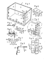
- FIG. 1 With reference to Figure 1 is illustrated in perspective view a box 1 , having four side components 2, 3, 4 and 5 and a base 6 .
- the box 1 may very well be provided with a lid, said lid not being shown in Figure 1, however.
- FIG. 1 and 2 What is thus illustrated in Figures 1 and 2 is an arrangement permitting the secure but separable connection of an edge part 4a of the first side component 4 of a box to an adjacent edge part 5a of the second side component 5 of a box.
- Each edge part is provided with a number of means intended to produce the connection.
- the means 7 for one of the edge parts 4a and the means 8 for the second edge part 5a are so executed in relation to each other that, irrespective of their direction or position lengthwise along the respective edge part, said edge parts will exhibit means which correspond to each other and which are capable of interacting with each other.
- These means have been allocated the reference designations 7a and 8a in Figure 2.
- a separate connecting organ 9 is so arranged as to be capable of interacting with means 7a, 8a which correspond to each other by inserting the connecting organ in the form of an angled plate into the means 8a executed in the form of a projection and the means 7a executed in the form of a projection.
- the means 7b does not consititute a corresponding means of this kind, but that the means 7c , on the other hand, does constitute a means which corresponds to the means 8a .
- the means of the first edge part 4a will thus be in the form of a number of projections or slots arranged one after the other so as to form a strip.
- the strip is in the form of a metal strip with embossed areas or stamped depressions to form projections or slots, and with securing organs (not shown in the Figure) formed on the part 7' so as to secure the strip 7 to the edge part 4a .
- a side component 4 is provided along an edge part 4a with an edge strip which is in turn provided along its length with a number of projections or slots arranged at a certain distance from each other
- a second side component 5 is provided along an edge part 5a with a number of projections or slots arranged at a certain distance from each other
- a connecting organ in the form of an angled plate 9 which could be replaced by a wire or similar, connects corresponding projections to each other.
- the edge strip 7 is bent in such a way that a component 7' is secured via securing organs not shown in the Figure to the edge part 4a of the side component and a component 7" forms an angle thereto and is so arranged as to extend beyond the end 4a' of the side component and for a certain distance along the edge part 5a of an adjacent side component.
- the projections or the slots are also formed at a certain distance from the Line of bending 10 and in the component which is so arranged as to extend along the edge part 5a of an adjacent side component 5 .
- Figure 2 also shows that the projections 7a, 7b or the slots in the strip are so executed as to be of identical length and as to exhibit an identical distance between adjacent projections or slots.
- Corresponding projections 8a or slots have a length which is identical with or greater than the distance 7a' between the projections 7a, 7c or the slots in the strip and are twice the width of the separate connecting organ 9 .
- bent edge strip 7 can also be secured with advantage to a base and/or lid, when the securing means 8 in the form of projections or slots 8a can be arranged along the side parts.
- the projections or slots are also so arranged as to reduce or prevent the ingress of water. This may be achieved most easily by causing the slots on the component 7" to be situated next to the end surface 4a' but at a certain distance from the line of bending 10 . These requirements are particularly applicable to the base and the lid, in respect of which it is also essential for adjacent edge parts to be straight.
- Figure 3 With reference to Figure 3 is illustrated in plan view the arrangement in accordance with Figure 2 in which the connecting organ 9 is shown to be bent around the securing means 7a and the securing means 8a , in such a way that the end parts 9a and 9b are situated above the securing means.
- Figure 3 also shows that the securing means 8a can assume a position other than that illustrated in Figure 2, but without jeopardizing the interaction between the means 7a and the securing means 8a via the connecting organ 9 .
- Figure 4 shows a section IV-IV in Figure 3
- Figure 5 shows a section V-V in Figure 3. Similar components have been allocated similar reference designations.
- FIG. 6 With reference to Figure 6 is illustrated an alternative connecting organ 9' having a metal strip bent to a right angle at one end 9a' and bent through only a small angle at the other end 9b' .
- Conditions are created in this way permitting the connecting organ 9' to be introduced in a simple fashion through the projection 8a and the projection 7a and permitting the component 9a' to be bent over the projection 8a and the component 9b' over the projection 7a .
- the embodiment in accordance with Figure 6 facilitates the introduction of the connecting organ, at the same time as conditions are created in this way permitting simple assembly, since the connecting organ will, on being bent, force the projections 8a and 7a together, in so doing improving the holding together of the edge parts.
- a separate corner reinforcement which is so arranged as to be capable of being secured either to the lid or to the base and to one or more of the corners of the box. Conditions are created in this way permitting the corner reinforcement to be dimensioned more strongly than the metal strips with their securing means. All that is required here is to ensure that the metal strips do not run all the way to the corner, and that a certain distance is left in this area which corresponds more or less to the size of the corner reinforcement.
- the corner reinforcement 11 is provided with two arms 12, 13 , the free ends 12a and 13a of which are provided with an overhanging part capable of enclosing one end of a metal strip. Also illustrated in Figure 7 is the manner in which the corner fitting is provided with an additional tongue 14, 14a , although this could, of course, be omitted.
- FIG. 8 is shown an alternative embodiment of a metal strip similar to the metal strip 7 .
- This metal strip exhibits a smooth surface 15 intended to be secured to the side component 4 via securing organs not shown in the Figure, and is also executed with an angled component 16 .
- the edge part in this case consists of an angled strip having a first component secured to the edge part 4 and a second component extending towards the adjacent edge part 5a .
- the second component is executed with an overhanging part 17 intended to form a slot to accommodate a depression 18 designed to provide the connection.
- the slot has been allocated the reference designation 19 .
- the strip is bent through an angle of 180 0 to provide reinforcement at the point indicated by the reference designation 20 . This provides an opportunity to stack one or more lids or bases one on top of the other.
- the construction is also so arranged that, even in the case of Large* boxes, the connecting organs may be brought simply into interaction with corresponding securing means.
- the securing means are also so executed as not to exhibit any component which extends beyond the upper edge part of the box.
- the embodiment of the connecting organ in accordance with Figure 6 can be provided with holes 21, 22 , through which holes can be introduced a wire for sealing the box, thus enabling the box to be sealed in a simple fashion.
- the invention also proposes a method of manufacturing a box consisting of a number of components capable of being connected together, in which amongst other things an edge part of one component must be capable of being connected to an edge part of an adjacent component, said connection being effected via means designed to produce the connection secured to each edge part, and said components (side components and base and/or lid) being cut to size and manufactured, for example from plywood, to a dimension corresponding to the expected volume of the box, and said edge part which is intended to be able to interact in a secure but separable fashion with an adjacent edge part being provided with a number of the means intended to produce the connection.
- the invention proposes in particular that the means intended for one edge part shall be secured irrespective of the expected direction or position of the means intended for an adjacent edge part, whereas the means intended for the adjacent edge part shall be secured irrespective of the expected direction or position of the means for the edge part.
- the means 8 will be applied to the edge part in relation to the anticipated load and the size of the box, and not in relation to the securing means present on the strip 7 .
- a number of components must accordingly be arranged next to each other in a-previously disclosed fashion, in such a way that amongst other things edge parts provided with securing means are positioned next to each other.
- each of the securing means for the edge part shall be so arranged as to interact with such securing means on an adjacent edge part as are found to correspond to each other.
- a strip provided with first securing means shall be secured to an edge part, and that other securing means separate from the first securing means on the strip shall be secured to an adjacent edge part.
- a strip may be bent to an angle, with one part attached to the edge part and so arranged that its other part will cover and extend towards the end surface of the component. It has been found to be particuLarLy desirable to cause the second securing means to be in the form of discrete securing means positioned along the edge piece.
- discrete securing means is used in this context to denote the presence of a certain distance between individual securing organs situated next to each other, within which space no corresponding securing means are present.
- a separate connecting organ shall be capable of being arranged for the purpose of connecting together corresponding securing means.
- FIG. 9 is shown an alternative embodiment of a metal strip similar to the metal strip 7 .
- This metal strip exhibits a smooth surface 15 intended to be secured to the side component 4 via securing organs 25 shown in the Figure and is also executed with an angled component 16'.
- the edge part in this case consists of an angled strip having a first component secured to the edge part 4 and a second component extending towards the adjacent edge part 5a .
- the second component is executed with an overhanging part 17' intended to form a slot to accommodate a depression 18' designed to provide the connection.
Landscapes
- Engineering & Computer Science (AREA)
- Wood Science & Technology (AREA)
- Mechanical Engineering (AREA)
- Life Sciences & Earth Sciences (AREA)
- Cartons (AREA)
- Rigid Containers With Two Or More Constituent Elements (AREA)
- Bending Of Plates, Rods, And Pipes (AREA)
- Connection Of Plates (AREA)
- Making Paper Articles (AREA)
- Accessory Devices And Overall Control Thereof (AREA)
- Details Of Rigid Or Semi-Rigid Containers (AREA)
- Acyclic And Carbocyclic Compounds In Medicinal Compositions (AREA)
- Medicines Containing Antibodies Or Antigens For Use As Internal Diagnostic Agents (AREA)
- Saccharide Compounds (AREA)
- Containers And Packaging Bodies Having A Special Means To Remove Contents (AREA)
- Connection Or Junction Boxes (AREA)
- Detergent Compositions (AREA)
- Design And Manufacture Of Integrated Circuits (AREA)
- Coupling Device And Connection With Printed Circuit (AREA)
- Connections Effected By Soldering, Adhesion, Or Permanent Deformation (AREA)
Priority Applications (1)
| Application Number | Priority Date | Filing Date | Title |
|---|---|---|---|
| AT84850344T ATE39902T1 (de) | 1983-11-09 | 1984-11-08 | Verfahren zum herstellen eines kastens und vorrichtung zur sicheren aber loesbaren verbindung eines randteils eines ersten bauteils mit einem angrenzenden randteil eines zweiten bauteils. |
Applications Claiming Priority (2)
| Application Number | Priority Date | Filing Date | Title |
|---|---|---|---|
| SE8306155 | 1983-11-09 | ||
| SE8306155A SE442823B (sv) | 1983-11-09 | 1983-11-09 | Sett att framstella en lada samt anordning for att fast men lostagbart forena ett kantparti for en forsta del med ett intillvarande kantparti for en andra del |
Publications (3)
| Publication Number | Publication Date |
|---|---|
| EP0143098A2 true EP0143098A2 (fr) | 1985-05-29 |
| EP0143098A3 EP0143098A3 (en) | 1986-08-27 |
| EP0143098B1 EP0143098B1 (fr) | 1989-01-11 |
Family
ID=20353242
Family Applications (1)
| Application Number | Title | Priority Date | Filing Date |
|---|---|---|---|
| EP84850344A Expired EP0143098B1 (fr) | 1983-11-09 | 1984-11-08 | Procédé de fabrication d'une boîte et dispositif permettant la fixation sûre mais séparable d'un bord d'un premier élément au bord adjacent d'un deuxième élément |
Country Status (11)
| Country | Link |
|---|---|
| US (1) | US4671422A (fr) |
| EP (1) | EP0143098B1 (fr) |
| JP (1) | JPS60123343A (fr) |
| AT (1) | ATE39902T1 (fr) |
| CA (1) | CA1227108A (fr) |
| DE (1) | DE3476050D1 (fr) |
| DK (1) | DK160476C (fr) |
| ES (1) | ES293423Y (fr) |
| FI (1) | FI75317C (fr) |
| NO (1) | NO165669C (fr) |
| SE (1) | SE442823B (fr) |
Cited By (1)
| Publication number | Priority date | Publication date | Assignee | Title |
|---|---|---|---|---|
| EP0457118A1 (fr) * | 1990-05-08 | 1991-11-21 | V-Link Systems Handelsbolag | Emballage de transport |
Families Citing this family (4)
| Publication number | Priority date | Publication date | Assignee | Title |
|---|---|---|---|---|
| WO1987005582A1 (fr) * | 1986-03-19 | 1987-09-24 | Graham Andrew S Jr | Systeme d'interconnection de panneaux de conteneurs |
| US5875910A (en) * | 1997-08-28 | 1999-03-02 | Advance Wire Products Ltd. | Orchard bin corners and joining brackets |
| SE521235C2 (sv) * | 2001-11-13 | 2003-10-14 | Foldy Pac Nordic Ab | Sätt att framställa en låda, förbindningsanordning härför, låda samt förbindningselement |
| CN104085598A (zh) * | 2014-07-16 | 2014-10-08 | 常熟市天力包装有限公司 | 一种固定卡扣结构 |
Family Cites Families (19)
| Publication number | Priority date | Publication date | Assignee | Title |
|---|---|---|---|---|
| DE40709C (de) * | L. FINK in Berlin, Bernauerstr. 40/41 | Zerlegbare Pappkasten | ||
| DE450693C (de) * | 1924-12-15 | 1927-10-13 | Garrett Russell | Beschlag aus zwei Teilen zum loesbaren Verbinden, insbesondere von Moebelteilen, mittls eines in die Beschlagteile einsteckbaren Bolzens |
| US1737186A (en) * | 1928-03-06 | 1929-11-26 | William H Champlin | Box |
| GB407961A (en) * | 1931-09-22 | 1934-03-22 | Hermann Elting | Improvements in collapsible containers such as packing cases |
| GB513675A (en) * | 1938-01-10 | 1939-10-19 | Jacob Mouchly | Improvements in and relating to collapsible containers for the transport of fruit, vegetables, poultry and the like |
| GB510660A (en) * | 1938-12-12 | 1939-08-04 | Arduino Uderzo | Dismountable case of wood for transport or storage of goods |
| FR911753A (fr) * | 1945-02-02 | 1946-07-19 | Procédé d'assemblage de panneaux pour la confection de caisses démontables et produit nouveau en résultant | |
| US2801761A (en) * | 1952-05-30 | 1957-08-06 | Pigatti Antonio | Knockdown container |
| US2896808A (en) * | 1958-04-30 | 1959-07-28 | Hugh R Papy | Box-like structure |
| US3047183A (en) * | 1959-09-03 | 1962-07-31 | Papa Rene | Container constituting a dismantlable flower pot |
| US3144951A (en) * | 1962-03-15 | 1964-08-18 | Rohr Corp | Demountable self-locking container |
| US3246787A (en) * | 1964-02-27 | 1966-04-19 | Gay Bell Corp | Knockdown shipping container |
| US3477604A (en) * | 1967-03-15 | 1969-11-11 | Charles E Kridle | Demountable containers and bases and panel joints thereof |
| US3403641A (en) * | 1967-11-24 | 1968-10-01 | Richard J Smith | Brackets for assembling knockdown cabinets |
| DK143223B (da) * | 1970-01-19 | 1981-07-27 | Nefab Plywoodemballage Ab | Sammenklappelig emballage |
| GB1310962A (en) * | 1970-06-26 | 1973-03-21 | Presnick M C | Containers and to wall sections therefor |
| US3990599A (en) * | 1975-08-05 | 1976-11-09 | Mary Edwin Thorpe Rowley | Reusable shipping container |
| JPS532205U (fr) * | 1976-06-24 | 1978-01-11 | ||
| JPS54703A (en) * | 1977-06-03 | 1979-01-06 | Hitachi Ltd | Electric machine winding |
-
1983
- 1983-11-09 SE SE8306155A patent/SE442823B/sv not_active IP Right Cessation
-
1984
- 1984-11-07 JP JP59235930A patent/JPS60123343A/ja active Pending
- 1984-11-07 NO NO844429A patent/NO165669C/no unknown
- 1984-11-08 DE DE8484850344T patent/DE3476050D1/de not_active Expired
- 1984-11-08 FI FI844397A patent/FI75317C/fi not_active IP Right Cessation
- 1984-11-08 EP EP84850344A patent/EP0143098B1/fr not_active Expired
- 1984-11-08 CA CA000467300A patent/CA1227108A/fr not_active Expired
- 1984-11-08 AT AT84850344T patent/ATE39902T1/de not_active IP Right Cessation
- 1984-11-08 ES ES1984293423U patent/ES293423Y/es not_active Expired
- 1984-11-09 DK DK534684A patent/DK160476C/da active
-
1986
- 1986-04-09 US US06/850,085 patent/US4671422A/en not_active Expired - Fee Related
Cited By (1)
| Publication number | Priority date | Publication date | Assignee | Title |
|---|---|---|---|---|
| EP0457118A1 (fr) * | 1990-05-08 | 1991-11-21 | V-Link Systems Handelsbolag | Emballage de transport |
Also Published As
| Publication number | Publication date |
|---|---|
| ES293423Y (es) | 1987-08-16 |
| NO844429L (no) | 1985-05-10 |
| SE442823B (sv) | 1986-02-03 |
| JPS60123343A (ja) | 1985-07-02 |
| FI844397A0 (fi) | 1984-11-08 |
| SE8306155D0 (sv) | 1983-11-09 |
| DK534684D0 (da) | 1984-11-09 |
| EP0143098A3 (en) | 1986-08-27 |
| DE3476050D1 (en) | 1989-02-16 |
| DK534684A (da) | 1985-05-10 |
| FI75317B (fi) | 1988-02-29 |
| ATE39902T1 (de) | 1989-01-15 |
| SE8306155L (sv) | 1985-05-10 |
| DK160476B (da) | 1991-03-18 |
| EP0143098B1 (fr) | 1989-01-11 |
| FI844397L (fi) | 1985-05-10 |
| US4671422A (en) | 1987-06-09 |
| NO165669B (no) | 1990-12-10 |
| FI75317C (fi) | 1988-06-09 |
| DK160476C (da) | 1991-09-09 |
| CA1227108A (fr) | 1987-09-22 |
| NO165669C (no) | 1991-03-20 |
| ES293423U (es) | 1987-01-01 |
Similar Documents
| Publication | Publication Date | Title |
|---|---|---|
| US4637544A (en) | Process for the manufacture of boxes, the boxes which result therefrom and the elements for their composition | |
| EP0675056A1 (fr) | Boîte à couvercle rabattant pour des cigarettes ou similaire | |
| US7246737B2 (en) | Stackable box for perishable products | |
| CA2133274A1 (fr) | Boite electrique pliable | |
| EP0143098B1 (fr) | Procédé de fabrication d'une boîte et dispositif permettant la fixation sûre mais séparable d'un bord d'un premier élément au bord adjacent d'un deuxième élément | |
| US3941305A (en) | Containers with reclosable opening means | |
| US4131229A (en) | Lock top for folding carton | |
| GB1570525A (en) | Packets | |
| JPH059303Y2 (fr) | ||
| FI78435B (fi) | Av ett aemne framstaellbar ask. | |
| US4149666A (en) | Packet, especially to contain cigarettes | |
| ITTO990638A1 (it) | Scatola ad incasso suscettibile di essere accoppiata con un'altra in particolare per apparecchiatura elettrica. | |
| EP0656294A1 (fr) | Boîte en carton matricé | |
| JPS6116983Y2 (fr) | ||
| JPH0136739Y2 (fr) | ||
| JPH0222292Y2 (fr) | ||
| JPS6339943Y2 (fr) | ||
| JPH0315463Y2 (fr) | ||
| JPH0437071Y2 (fr) | ||
| JPH06321232A (ja) | 包装箱 | |
| JPS6340425Y2 (fr) | ||
| JPH0716585Y2 (ja) | 包装用箱 | |
| JPH0118521Y2 (fr) | ||
| JPS594891Y2 (ja) | 包装箱の組立用素板 | |
| JP2548997Y2 (ja) | プルボックス |
Legal Events
| Date | Code | Title | Description |
|---|---|---|---|
| PUAI | Public reference made under article 153(3) epc to a published international application that has entered the european phase |
Free format text: ORIGINAL CODE: 0009012 |
|
| AK | Designated contracting states |
Designated state(s): AT BE CH DE FR GB IT LI NL SE |
|
| PUAL | Search report despatched |
Free format text: ORIGINAL CODE: 0009013 |
|
| AK | Designated contracting states |
Kind code of ref document: A3 Designated state(s): AT BE CH DE FR GB IT LI NL SE |
|
| 17P | Request for examination filed |
Effective date: 19860915 |
|
| 17Q | First examination report despatched |
Effective date: 19870916 |
|
| GRAA | (expected) grant |
Free format text: ORIGINAL CODE: 0009210 |
|
| AK | Designated contracting states |
Kind code of ref document: B1 Designated state(s): AT BE CH DE FR GB IT LI NL SE |
|
| PG25 | Lapsed in a contracting state [announced via postgrant information from national office to epo] |
Ref country code: SE Effective date: 19890111 |
|
| REF | Corresponds to: |
Ref document number: 39902 Country of ref document: AT Date of ref document: 19890115 Kind code of ref document: T |
|
| REF | Corresponds to: |
Ref document number: 3476050 Country of ref document: DE Date of ref document: 19890216 |
|
| ET | Fr: translation filed | ||
| ITF | It: translation for a ep patent filed | ||
| PLBE | No opposition filed within time limit |
Free format text: ORIGINAL CODE: 0009261 |
|
| STAA | Information on the status of an ep patent application or granted ep patent |
Free format text: STATUS: NO OPPOSITION FILED WITHIN TIME LIMIT |
|
| 26N | No opposition filed | ||
| ITTA | It: last paid annual fee | ||
| PGFP | Annual fee paid to national office [announced via postgrant information from national office to epo] |
Ref country code: NL Payment date: 19921130 Year of fee payment: 9 |
|
| PGFP | Annual fee paid to national office [announced via postgrant information from national office to epo] |
Ref country code: GB Payment date: 19930427 Year of fee payment: 9 |
|
| PGFP | Annual fee paid to national office [announced via postgrant information from national office to epo] |
Ref country code: AT Payment date: 19930429 Year of fee payment: 9 |
|
| PGFP | Annual fee paid to national office [announced via postgrant information from national office to epo] |
Ref country code: FR Payment date: 19930526 Year of fee payment: 9 |
|
| PGFP | Annual fee paid to national office [announced via postgrant information from national office to epo] |
Ref country code: BE Payment date: 19930603 Year of fee payment: 9 |
|
| PG25 | Lapsed in a contracting state [announced via postgrant information from national office to epo] |
Ref country code: GB Effective date: 19931108 Ref country code: AT Effective date: 19931108 |
|
| PG25 | Lapsed in a contracting state [announced via postgrant information from national office to epo] |
Ref country code: BE Effective date: 19931130 |
|
| BERE | Be: lapsed |
Owner name: BJORKLUND GUNNAR EVERT Effective date: 19931130 |
|
| PG25 | Lapsed in a contracting state [announced via postgrant information from national office to epo] |
Ref country code: NL Effective date: 19940601 |
|
| GBPC | Gb: european patent ceased through non-payment of renewal fee |
Effective date: 19931108 |
|
| NLV4 | Nl: lapsed or anulled due to non-payment of the annual fee | ||
| PG25 | Lapsed in a contracting state [announced via postgrant information from national office to epo] |
Ref country code: FR Effective date: 19940729 |
|
| REG | Reference to a national code |
Ref country code: FR Ref legal event code: ST |
|
| PGFP | Annual fee paid to national office [announced via postgrant information from national office to epo] |
Ref country code: CH Payment date: 19941109 Year of fee payment: 11 |
|
| PG25 | Lapsed in a contracting state [announced via postgrant information from national office to epo] |
Ref country code: LI Effective date: 19951130 Ref country code: CH Effective date: 19951130 |
|
| REG | Reference to a national code |
Ref country code: CH Ref legal event code: PL |
|
| PGFP | Annual fee paid to national office [announced via postgrant information from national office to epo] |
Ref country code: DE Payment date: 20040127 Year of fee payment: 20 |