EP0143108A1 - Dispositif transporteur pour le réservoir d'une récolteuse - Google Patents
Dispositif transporteur pour le réservoir d'une récolteuse Download PDFInfo
- Publication number
- EP0143108A1 EP0143108A1 EP83111398A EP83111398A EP0143108A1 EP 0143108 A1 EP0143108 A1 EP 0143108A1 EP 83111398 A EP83111398 A EP 83111398A EP 83111398 A EP83111398 A EP 83111398A EP 0143108 A1 EP0143108 A1 EP 0143108A1
- Authority
- EP
- European Patent Office
- Prior art keywords
- conveyor
- screw
- drive
- collecting container
- screw conveyors
- Prior art date
- Legal status (The legal status is an assumption and is not a legal conclusion. Google has not performed a legal analysis and makes no representation as to the accuracy of the status listed.)
- Granted
Links
- 238000003306 harvesting Methods 0.000 claims abstract description 7
- 230000005540 biological transmission Effects 0.000 description 1
- 238000002485 combustion reaction Methods 0.000 description 1
- 238000000034 method Methods 0.000 description 1
Images

Classifications
-
- A—HUMAN NECESSITIES
- A01—AGRICULTURE; FORESTRY; ANIMAL HUSBANDRY; HUNTING; TRAPPING; FISHING
- A01D—HARVESTING; MOWING
- A01D41/00—Combines, i.e. harvesters or mowers combined with threshing devices
- A01D41/12—Details of combines
- A01D41/1208—Tanks for grain or chaff
- A01D41/1217—Unloading mechanisms
-
- A—HUMAN NECESSITIES
- A01—AGRICULTURE; FORESTRY; ANIMAL HUSBANDRY; HUNTING; TRAPPING; FISHING
- A01D—HARVESTING; MOWING
- A01D41/00—Combines, i.e. harvesters or mowers combined with threshing devices
- A01D41/12—Details of combines
- A01D41/1208—Tanks for grain or chaff
-
- B—PERFORMING OPERATIONS; TRANSPORTING
- B65—CONVEYING; PACKING; STORING; HANDLING THIN OR FILAMENTARY MATERIAL
- B65G—TRANSPORT OR STORAGE DEVICES, e.g. CONVEYORS FOR LOADING OR TIPPING, SHOP CONVEYOR SYSTEMS OR PNEUMATIC TUBE CONVEYORS
- B65G65/00—Loading or unloading
- B65G65/30—Methods or devices for filling or emptying bunkers, hoppers, tanks, or like containers, of interest apart from their use in particular chemical or physical processes or their application in particular machines, e.g. not covered by a single other subclass
- B65G65/34—Emptying devices
- B65G65/40—Devices for emptying otherwise than from the top
- B65G65/46—Devices for emptying otherwise than from the top using screw conveyors
Definitions
- the invention relates to a conveyor device for the collecting container of a harvesting machine, in particular a combine harvester, with a plurality of screw conveyors which can be driven by at least one drive device, at least one screw conveyor being arranged transversely to the other screw conveyors.
- a conveyor device for the collecting container of a combine harvester is known (US Pat. No. 4,100,720), which is formed from a continuous worm shaft with numerous worm helices, part of the worm helices being omitted for accommodating a gear housing, so that the gear housing for accommodating the shaft can serve.
- the gearbox there are two bevel gears, one of which is connected to the shaft of the screw conveyor and the other to a drive shaft which has a sprocket at the end for driving the screw conveyor.
- the gear housing is connected to a pipe extension for receiving the drive shaft, which is connected to a wall part of the combine harvester via a flange.
- a conveyor device for the collecting container of a combine harvester is known (DE-GM 6 601 149), which consists of three screw conveyors which are arranged parallel to one another in troughs in the bottom of the collecting container and which are used to feed a discharge screw conveyor.
- the discharge screw is connected at the end to a height conveyor and is driven by a chain gear.
- the three screw conveyors running parallel to each other each have a sprocket at the end, so that they can be connected to one another by means of chains.
- One of the three screw conveyors is connected to another drive device via a further sprocket.
- Such a device for A ⁇ drive of the three conveyor screws running parallel to each other and the discharge screw running transversely to it is complex and expensive due to the use of two separate drive systems.
- the invention has for its object to design and arrange the conveyor device for driving the individual screw conveyors in such a way that a minimum of drive elements and components for mounting the screw conveyors can be used.
- This object has been achieved in that only one drive device is provided for all screw conveyors and the drive is in each case directed from one screw conveyor to the other screw conveyors, the screw conveyors being able to be supported, at least in part, via the bearings or housing parts accommodating the drive elements in the collecting container. Since only one drive device is provided for all screw conveyors, a very inexpensive conveyor device is obtained for the collecting container of the harvesting machine or the combine harvester. A reduction in the cost of the conveyor device is also achieved in that the drive elements are accommodated in bearings or housing parts which can simultaneously serve to support the individual screw conveyors or the entire conveyor device. In addition to a very inexpensive drive device, this also provides simple storage of the individual screw conveyors in the collecting container.
- At least two screw conveyors run parallel to one another and are connected at the end to bevel gears with a transverse screw conveyor, the bevel gears being received in pairs in a gear housing which can be supported on the bottom or on the walls of the collecting container.
- the screw conveyors running parallel to one another in troughs in the bottom of the collecting container are supported at their drive-free end via bearings in the collecting container and the drivable ends can be supported via the gear housing on the transverse screw conveyor, each of which ends in the Side walls stored and can be drive-connectable with another emptying device.
- the two parallel screw conveyors can be supported like a bridge.
- the drive of screw conveyors, which are arranged transversely to the other screw conveyor can be easily passed on from one screw conveyor to the other screw conveyor.
- the screw conveyor connected to the emptying device for receiving the one bearing housing is divided or made in one piece.
- the screw conveyor connected to the emptying device has a drive pulley for driving all screw conveyors and the emptying device and that the gear housing is formed from two housing parts which can be joined together and at least one housing part via struts to the floor or the walls of the Collection container is detachably connected. Since the gear housing is formed from two housing parts, the one screw conveyor can be connected to the transverse screw in a very short time and supported on the struts provided on the housing part on the floor or on the side walls of the collecting container. Should the individual gear wheels be replaced, then only one housing part needs to be removed in order to gain access to the drive elements.
- 10 in FIG. 1 denotes a combine harvester which is equipped with front wheels 12 and rear wheels 14.
- a harvesting device 16 which consists of a reel 18, a cutting device 20 and an auger 22 and which is connected to a vertically pivotable inclined conveyor housing 24.
- the crop is fed via the harvesting device 16 and the inclined conveyor housing 24 to a threshing drum, not shown in the drawing.
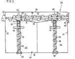
- the driver platform 26 In the front area of the combine 10 there is the driver platform 26 and behind this there is a collecting container 28 with an emptying device 30, which is connected to the lower end of the collecting container and can be fed via a (Fig. 2) transverse conveyor screw 76.
- the collecting container 28 consists of two side walls 32 and 34 which extend in the direction of travel, as well as a front wall 36 and a rear wall 38.
- the collecting container has a bottom 40 which consists of two obliquely running, mutually roof-shaped bottom parts 42 and 44 is formed, each of which merges into a depression 46 and 48 in the region of the side wall 32 and 34 and which are connected to the corresponding side wall 32 and 34, respectively.
- the two base parts 42 and 44 also abut a transverse, also inclined base part 50, which also merges into a depression 52 which abuts the front wall 36.
- the gear housing 62 or 64 which is only indicated schematically in FIG. 3, can consist of two housing parts releasably connected to one another, in each of which bevel gear pairs 70 and 72 are arranged.
- the bevel gear 70 of the gear housing 62 on the left with reference to the drawing is arranged at the end of the shaft 66 and is in engagement with the bevel gear 72 which is arranged in the region of the end of a further transverse shaft 74 of a screw conveyor 76.
- the conveyor screw 76 extends just above the trough 52 and is fed with crop material via the two conveyor screws 56 and 58 extending in the direction of travel.
- the bevel gear 72 arranged in the right gear housing 64 is pushed onto the shaft 74 and is in drive connection with the bevel gear 70 of the shaft 68.
- the shaft 74 is extended beyond the bevel gear 72 and is rotatably received in a bearing 78 arranged in the side wall 34.
- a drive pulley 80 which can be designed as a traction means pulley and is drive-connected via appropriate traction mechanism drives to an internal combustion engine (not shown in the drawing) of the combine harvester 10.
- the left gear housing 62 is connected to a strut 82 which ends at one end .
- the front wall 36 is firmly connected at the other end to a bracket 84 which is supported on the floor 40 and thereby surrounds the screw conveyor 56 in a fork-shaped manner.
- the right gear housing 64 is supported in the same way via a strut 88 and a bracket 90.
- the brackets 84 and 90 can advantageously also serve to accommodate cover plates, not shown in the drawing.
- gear housing 62 or 64 By using the gear housing 62 or 64 with the associated bevel gears 70 and 72, an advantageous drive connection is thus obtained between the conveyor screws 56 and 58 extending in the direction of travel with the transverse screw conveyor 76.
- the gear housing 62, 64 can simultaneously support the corresponding ends of the shafts 66 and 68 and serve to support the shaft 74, so that the support of the shaft 74 in the side walls 32, 34 is not necessary.
- an advantageous, inexpensive support of all working elements can be achieved.
- the screw conveyor 76 and thus the two screw conveyors 56 and 58 are driven, which serve to empty the collecting container 28 and feed the crop to the transverse screw conveyor 76, which is not used for loading one in the drawing screw conveyor of the emptying device 30 serves.
- the corresponding emptying device must be fed via a vertical conveyor 92 (FIG. 2), which can be equipped with a screw conveyor, which is also driven by the shaft 74.
- the screw conveyor of the vertical conveyor 92 can be drive-connected to the shaft 74 via bevel gears, also not shown. In this way, all shafts in the collecting container 28 can be driven by a single drive device.
- the vertical conveyor 92 it is also possible to enable the drive connection between the screw conveyor 76 and the screw conveyor of the vertical conveyor 92 via a chain transmission.
- the shaft 74 according to FIG. 2 is driven similarly to FIG. 3 via a V-belt pulley (not shown), which can be provided at the left end of the shaft 74.
- the shaft 74 is guided through the left side wall 32.
- the crop is fed in the direction of the arrows 100 and 102 to the transverse screw conveyor 76, which feeds the crop in the direction of the arrow 104 to the vertical conveyor 92, via which the crop can be discharged to the outside in a loading wagon.
Landscapes
- Life Sciences & Earth Sciences (AREA)
- Environmental Sciences (AREA)
- Engineering & Computer Science (AREA)
- Mechanical Engineering (AREA)
- Threshing Machine Elements (AREA)
- Harvester Elements (AREA)
Priority Applications (2)
| Application Number | Priority Date | Filing Date | Title |
|---|---|---|---|
| DE8383111398T DE3379861D1 (en) | 1983-11-15 | 1983-11-15 | Conveyor device for the container of a crop harvester |
| EP83111398A EP0143108B1 (fr) | 1983-11-15 | 1983-11-15 | Dispositif transporteur pour le réservoir d'une récolteuse |
Applications Claiming Priority (1)
| Application Number | Priority Date | Filing Date | Title |
|---|---|---|---|
| EP83111398A EP0143108B1 (fr) | 1983-11-15 | 1983-11-15 | Dispositif transporteur pour le réservoir d'une récolteuse |
Publications (2)
| Publication Number | Publication Date |
|---|---|
| EP0143108A1 true EP0143108A1 (fr) | 1985-06-05 |
| EP0143108B1 EP0143108B1 (fr) | 1989-05-17 |
Family
ID=8190807
Family Applications (1)
| Application Number | Title | Priority Date | Filing Date |
|---|---|---|---|
| EP83111398A Expired EP0143108B1 (fr) | 1983-11-15 | 1983-11-15 | Dispositif transporteur pour le réservoir d'une récolteuse |
Country Status (2)
| Country | Link |
|---|---|
| EP (1) | EP0143108B1 (fr) |
| DE (1) | DE3379861D1 (fr) |
Cited By (5)
| Publication number | Priority date | Publication date | Assignee | Title |
|---|---|---|---|---|
| EP0528310A1 (fr) * | 1991-08-16 | 1993-02-24 | Deere & Company | Système transporteur |
| CN103640905A (zh) * | 2013-12-16 | 2014-03-19 | 唐理舟 | 平房仓颗粒类物料自动化进出仓方法 |
| CN107444921A (zh) * | 2017-08-21 | 2017-12-08 | 安徽信息工程学院 | 一种谷物翻晒收集机 |
| US9907229B2 (en) | 2012-07-31 | 2018-03-06 | Agco A/S | Granule conveying apparatus |
| CN117416699A (zh) * | 2023-09-11 | 2024-01-19 | 安徽聚力粮机科技股份有限公司 | 基于大处理量的智能出仓机 |
Citations (7)
| Publication number | Priority date | Publication date | Assignee | Title |
|---|---|---|---|---|
| BE669961A (fr) * | 1964-09-24 | 1966-01-17 | ||
| BE757359R (nl) * | 1970-10-12 | 1971-03-16 | Clayson Nv | Verbeteringen aan maaidorsers |
| US3650052A (en) * | 1969-02-24 | 1972-03-21 | White Motor Canada | Crop harvesting combine |
| FR2157303A7 (fr) * | 1971-10-21 | 1973-06-01 | Laverda Spa Pietro | |
| DE2455246A1 (de) * | 1974-11-22 | 1976-05-26 | Bernhard Ruberg | Hochbunker mit austragsvorrichtung |
| BE841281A (nl) * | 1976-04-29 | 1976-08-16 | Opslagtank voor poedervorming materiaal en inrichting voor het ledigen ervan gebruikt bij deze opslagtank | |
| FR2355747A1 (fr) * | 1976-06-24 | 1978-01-20 | Finot Jean | Dispositif pour l'extraction de produits ensiles dans une capacite de stockage et capacite equipee dudit dispositif |
Family Cites Families (1)
| Publication number | Priority date | Publication date | Assignee | Title |
|---|---|---|---|---|
| DE2839841C2 (de) * | 1978-09-13 | 1987-03-05 | Klöckner-Humboldt-Deutz AG Zweigniederlassung Fahr, 7702 Gottmadingen | Mähwerk |
-
1983
- 1983-11-15 EP EP83111398A patent/EP0143108B1/fr not_active Expired
- 1983-11-15 DE DE8383111398T patent/DE3379861D1/de not_active Expired
Patent Citations (7)
| Publication number | Priority date | Publication date | Assignee | Title |
|---|---|---|---|---|
| BE669961A (fr) * | 1964-09-24 | 1966-01-17 | ||
| US3650052A (en) * | 1969-02-24 | 1972-03-21 | White Motor Canada | Crop harvesting combine |
| BE757359R (nl) * | 1970-10-12 | 1971-03-16 | Clayson Nv | Verbeteringen aan maaidorsers |
| FR2157303A7 (fr) * | 1971-10-21 | 1973-06-01 | Laverda Spa Pietro | |
| DE2455246A1 (de) * | 1974-11-22 | 1976-05-26 | Bernhard Ruberg | Hochbunker mit austragsvorrichtung |
| BE841281A (nl) * | 1976-04-29 | 1976-08-16 | Opslagtank voor poedervorming materiaal en inrichting voor het ledigen ervan gebruikt bij deze opslagtank | |
| FR2355747A1 (fr) * | 1976-06-24 | 1978-01-20 | Finot Jean | Dispositif pour l'extraction de produits ensiles dans une capacite de stockage et capacite equipee dudit dispositif |
Cited By (7)
| Publication number | Priority date | Publication date | Assignee | Title |
|---|---|---|---|---|
| EP0528310A1 (fr) * | 1991-08-16 | 1993-02-24 | Deere & Company | Système transporteur |
| US5443352A (en) * | 1991-08-16 | 1995-08-22 | Deere & Company | Combine grain tank discharge system |
| US9907229B2 (en) | 2012-07-31 | 2018-03-06 | Agco A/S | Granule conveying apparatus |
| CN103640905A (zh) * | 2013-12-16 | 2014-03-19 | 唐理舟 | 平房仓颗粒类物料自动化进出仓方法 |
| CN103640905B (zh) * | 2013-12-16 | 2016-06-29 | 唐理舟 | 平房仓颗粒类物料自动化进出仓方法 |
| CN107444921A (zh) * | 2017-08-21 | 2017-12-08 | 安徽信息工程学院 | 一种谷物翻晒收集机 |
| CN117416699A (zh) * | 2023-09-11 | 2024-01-19 | 安徽聚力粮机科技股份有限公司 | 基于大处理量的智能出仓机 |
Also Published As
| Publication number | Publication date |
|---|---|
| EP0143108B1 (fr) | 1989-05-17 |
| DE3379861D1 (en) | 1989-06-22 |
Similar Documents
| Publication | Publication Date | Title |
|---|---|---|
| EP0528310B1 (fr) | Système transporteur | |
| DE3029424A1 (de) | Reihenschneid-anbaugeraet | |
| DE2652162C2 (fr) | ||
| DE3125659A1 (de) | Selbstfahrender maehdrescher | |
| DE2037447C3 (de) | Mähdrescherkorntank | |
| EP0143108A1 (fr) | Dispositif transporteur pour le réservoir d'une récolteuse | |
| DE3016903C2 (fr) | ||
| DE2922796A1 (de) | Aufnahmevorrichtung bei einem selbstladewagen | |
| DE2743602B2 (de) | Vorrichtung zur Entnahme von Silage aus einem Silo | |
| DE2830069A1 (de) | Maehdrescher, der nach dem axialflussprinzip arbeitet | |
| DE873168C (de) | Maehhaecksler | |
| DE2058549A1 (de) | Erntemaschine,insbesondere selbstfahrender Maehdrescher | |
| DE2834782A1 (de) | Silagefraeser mit vorratsbehaelter | |
| DE2908268C2 (de) | Vorrichtung zur Verhinderung der Brückenbildung | |
| DE1958756C3 (de) | Aufladeeinrichtung für auf dem Boden liegendes Halmgut | |
| DE1221480B (de) | Selbstfahrender Maehdrescher | |
| DE2348817C3 (de) | Erntemaschine für Hackfrüchte | |
| DE814732C (de) | Schraemlademaschine | |
| DE2700577A1 (de) | Selbstfahrende erntemaschine, insbesondere maehdrescher mit einem von zwei seiten von den maehdrescherseitenwaenden begrenzten korntank | |
| DE2261440A1 (de) | Wurzelfruchterntemaschine | |
| DE2647469B2 (de) | Antriebsanordnung für die Fräswalze an sog. Silofräsen | |
| DE2851127A1 (de) | Futterautomat | |
| DE3034295C2 (de) | Vorrichtung zur Entnahme von Silage o.dgl. aus einem Silo o.dgl. | |
| DE102006040132A1 (de) | Mähgerät | |
| DD145487A1 (de) | Erntemaschine fuer kamilleblueten und andere drogenpflanzen |
Legal Events
| Date | Code | Title | Description |
|---|---|---|---|
| PUAI | Public reference made under article 153(3) epc to a published international application that has entered the european phase |
Free format text: ORIGINAL CODE: 0009012 |
|
| 17P | Request for examination filed |
Effective date: 19841026 |
|
| AK | Designated contracting states |
Designated state(s): AT BE CH DE FR GB IT LI LU NL SE |
|
| RBV | Designated contracting states (corrected) |
Designated state(s): BE DE FR GB IT SE |
|
| ITCL | It: translation for ep claims filed |
Representative=s name: LENZI & C. |
|
| EL | Fr: translation of claims filed | ||
| 17Q | First examination report despatched |
Effective date: 19860415 |
|
| ITF | It: translation for a ep patent filed | ||
| GRAA | (expected) grant |
Free format text: ORIGINAL CODE: 0009210 |
|
| AK | Designated contracting states |
Kind code of ref document: B1 Designated state(s): BE DE FR GB IT SE |
|
| PG25 | Lapsed in a contracting state [announced via postgrant information from national office to epo] |
Ref country code: SE Effective date: 19890517 Ref country code: GB Effective date: 19890517 Ref country code: FR Free format text: THE PATENT HAS BEEN ANNULLED BY A DECISION OF A NATIONAL AUTHORITY Effective date: 19890517 |
|
| REF | Corresponds to: |
Ref document number: 3379861 Country of ref document: DE Date of ref document: 19890622 |
|
| EN | Fr: translation not filed | ||
| PGFP | Annual fee paid to national office [announced via postgrant information from national office to epo] |
Ref country code: BE Payment date: 19891116 Year of fee payment: 7 |
|
| GBV | Gb: ep patent (uk) treated as always having been void in accordance with gb section 77(7)/1977 [no translation filed] | ||
| ITTA | It: last paid annual fee | ||
| PLBE | No opposition filed within time limit |
Free format text: ORIGINAL CODE: 0009261 |
|
| STAA | Information on the status of an ep patent application or granted ep patent |
Free format text: STATUS: NO OPPOSITION FILED WITHIN TIME LIMIT |
|
| 26N | No opposition filed | ||
| PG25 | Lapsed in a contracting state [announced via postgrant information from national office to epo] |
Ref country code: DE Effective date: 19900801 |
|
| PG25 | Lapsed in a contracting state [announced via postgrant information from national office to epo] |
Ref country code: BE Effective date: 19901130 |
|
| BERE | Be: lapsed |
Owner name: DEERE & CY Effective date: 19901130 |