EP0143145A2 - Etagère pour le stockage des boîtes de vernis - Google Patents
Etagère pour le stockage des boîtes de vernis Download PDFInfo
- Publication number
- EP0143145A2 EP0143145A2 EP84103215A EP84103215A EP0143145A2 EP 0143145 A2 EP0143145 A2 EP 0143145A2 EP 84103215 A EP84103215 A EP 84103215A EP 84103215 A EP84103215 A EP 84103215A EP 0143145 A2 EP0143145 A2 EP 0143145A2
- Authority
- EP
- European Patent Office
- Prior art keywords
- paint
- guide housing
- shaped guide
- drive
- base
- Prior art date
- Legal status (The legal status is an assumption and is not a legal conclusion. Google has not performed a legal analysis and makes no representation as to the accuracy of the status listed.)
- Granted
Links
Images


Classifications
-
- B—PERFORMING OPERATIONS; TRANSPORTING
- B44—DECORATIVE ARTS
- B44D—PAINTING OR ARTISTIC DRAWING, NOT OTHERWISE PROVIDED FOR; PRESERVING PAINTINGS; SURFACE TREATMENT TO OBTAIN SPECIAL ARTISTIC SURFACE EFFECTS OR FINISHES
- B44D3/00—Accessories or implements for use in connection with painting or artistic drawing, not otherwise provided for; Methods or devices for colour determination, selection, or synthesis, e.g. use of colour tables
- B44D3/06—Implements for stirring or mixing paints
-
- B—PERFORMING OPERATIONS; TRANSPORTING
- B01—PHYSICAL OR CHEMICAL PROCESSES OR APPARATUS IN GENERAL
- B01F—MIXING, e.g. DISSOLVING, EMULSIFYING OR DISPERSING
- B01F27/00—Mixers with rotary stirring devices in fixed receptacles; Kneaders
- B01F27/80—Mixers with rotary stirring devices in fixed receptacles; Kneaders with stirrers rotating about a substantially vertical axis
- B01F27/88—Mixers with rotary stirring devices in fixed receptacles; Kneaders with stirrers rotating about a substantially vertical axis with a separate receptacle-stirrer unit that is adapted to be coupled to a drive mechanism
-
- B—PERFORMING OPERATIONS; TRANSPORTING
- B01—PHYSICAL OR CHEMICAL PROCESSES OR APPARATUS IN GENERAL
- B01F—MIXING, e.g. DISSOLVING, EMULSIFYING OR DISPERSING
- B01F35/00—Accessories for mixers; Auxiliary operations or auxiliary devices; Parts or details of general application
- B01F35/30—Driving arrangements; Transmissions; Couplings; Brakes
- B01F35/32—Driving arrangements
- B01F35/323—Driving arrangements for vertical stirrer shafts
- B01F35/3231—Driving several stirrer shafts, e.g. about the same axis
-
- B—PERFORMING OPERATIONS; TRANSPORTING
- B01—PHYSICAL OR CHEMICAL PROCESSES OR APPARATUS IN GENERAL
- B01F—MIXING, e.g. DISSOLVING, EMULSIFYING OR DISPERSING
- B01F35/00—Accessories for mixers; Auxiliary operations or auxiliary devices; Parts or details of general application
- B01F35/40—Mounting or supporting mixing devices or receptacles; Clamping or holding arrangements therefor
- B01F35/42—Clamping or holding arrangements for mounting receptacles on mixing devices
-
- B—PERFORMING OPERATIONS; TRANSPORTING
- B65—CONVEYING; PACKING; STORING; HANDLING THIN OR FILAMENTARY MATERIAL
- B65G—TRANSPORT OR STORAGE DEVICES, e.g. CONVEYORS FOR LOADING OR TIPPING, SHOP CONVEYOR SYSTEMS OR PNEUMATIC TUBE CONVEYORS
- B65G1/00—Storing articles, individually or in orderly arrangement, in warehouses or magazines
- B65G1/02—Storage devices
Definitions
- the invention relates to a shelf and paint cans for inclusion in the shelf.
- the shelf consists of side vertical brackets and support plates extending between the supports at different vertical distances and a drive device with a drive motor and a drive transmission on each support plate to a series of first drive members on one side of each support plate, each for engagement with a second drive member is formed on a paint can.
- the paint can for inclusion in the shelf contains a lid in which a stirrer shaft is mounted, which carries an agitator on the inside of the lid and a second drive member on the outside of the lid.
- the lid is provided with a closure member for a pouring opening and with an opening lever which can be actuated against the force of a spring in the opening sense for the closure member.
- the support plates made of sheet steel and according to the dimensions of the various paint cans are arranged at different distances from one another on the supports.
- the drive transmission takes place by means of V-belts in the support plates, through which drive shafts extend downward, at the ends of which first drive members are pivotally arranged in the form of plates which extend downward on opposite sides of the drive shaft.
- the drive shafts and the first drive elements are arranged at a distance from one another which is determined by the diameter of the paint cans which are placed on the next lower support plate.
- Each paint can is sealed with a removable lid, on which a pouring opening can be closed by a spring-loaded closure member and in which a stirrer shaft is rotatably mounted.
- a second drive member is arranged in the form of a fork with upstanding ends adapted to the first drive member.
- the plates grip the upstanding ends of the fork and take them with them, so that the stirrer shaft is rotated. This rotation is necessary to ensure the homogeneity of the paint contained in the can over a long period of time.
- the drive elements which bring about the drive connection between the V-belt in the support plates and the agitators inside the paint cans, are freely accessible during operation, which is a considerable disadvantage for the occupational safety of these shelves.
- the paint cans can be moved freely on the support plates, so that when the paint can is placed on the shelf, it is not readily possible to achieve a perfect alignment between the first and second drive members and thus trouble-free power transmission.
- the object of the invention is to provide a shelf for paint cans of the type mentioned, which offers a high level of work and operational safety.
- this object is achieved in that on the side of the support plate from which the first drive members protrude, generally U-shaped guide housings are arranged for each one paint can, each of which encloses the first drive member.
- the inclusion of the drive members in the guide housing makes the drive connection and its moving parts inaccessible to external intervention. At the same time, the great advantage is achieved by the guide housing that the paint cans are guided into the shelf when they are set and that the drive elements of the drive connection are always perfectly aligned with one another.
- the U-shaped guide housing is preferably formed with a guide part which determines the position of the paint can on the shelf and a starting from the base of the U-shaped guide housing and at a distance from the edges of the side walls of the U- facing away from the support plate.
- shaped guide housing extending guide plate with a central and towards the base of the guide housing guide slot.
- each U-shaped guide housing also contains a latching element which extends on a side facing away from the base and at a distance from the protective wall between the side walls.
- the latch holds the paint can in a position in which the first and second drive elements are engaged.
- the aforementioned object is achieved in that a generally U-shaped guide member projecting from the outside of the lid is provided and a latching device is arranged on the opening lever.
- the base of the U-shaped guide member is advantageously arranged on the cover and the legs of the U-shaped guide member form guide elements that interact with the guide housing on the support plate.
- the latching device is preferably arranged on the side of the opening lever facing away from the cover and can form a latching member which projects from the opening lever and which cooperates with the latching element on the guide housing in order to drive the paint can in it secure aligned position.
- Such a design of the paint can achieves extensive and thus particularly effective guidance even with large-volume paint cans.
- the formation of the locking member on the opening lever enables the locking in the operating position against the spring of the opening lever, so that the paint can can only be removed from its operating position by actuating the opening lever and thus not inadvertently.
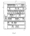
- side supports 1 and 2 can be seen, which are connected at the bottom by a base plate 3 and at the top by a cross member 4.
- the bottom plate 3 can, if necessary extend even further forward and the supports 1, 2 can optionally be provided with correspondingly projecting side parts; A table can be built over this part of the base plate.
- the cross member 4 can be provided with a lamp for illuminating the shelf.
- the supports 1 and 2, the base plate 3 and the cross member 4 can be made of any suitable material and are preferably made of sheet steel.
- rows of paint cans 41 of different sizes can be arranged standing on the support plates 5 of the shelf.
- further support plates for holding paint cans 41 can also be arranged under the table, if present.
- a control box 10 for a main drive motor in the form of an electric motor is attached to the carrier 1;
- a main drive shaft extends over the height of the carrier 1 and is in drive connection with the electric motor.
- drive disks for drive transmission to first drive members 11 are arranged on the main drive shaft by means of V-belts.
- the generally U-shaped guide housing 20 consist of two side walls 22 which are arranged parallel to one another and at a distance from one another such that they enclose the first drive member 11 between them.
- the side walls 22 are connected by a semicircular base 23. From the free ends of the side walls 22, laterally angled insertion members 24 extend (see FIG. 3) so far down that they force the paint cans 41 to run.
- a guide plate 26 extends from the base 23 with a guide slot 27. This guide slot 27 is arranged and designed such that it receives the stirrer shaft 42 protruding from the cover 40 of a paint can 41 when a paint can 41 is inserted into the guide housing 20.
- a protective wall 28 extends between the side walls 22, so that the first drive member 11 is enclosed between the base 23 and the protective wall 28.
- a slot with a stop 29 is formed on each side, on which the guide member described below, located on the outside of the lid of the paint can, rests when the paint can is in its operating position.
- a fastening part 30 runs close to the insertion members 24 and connects the edges of the opposite side walls 22 to one another and serves to fasten the U-shaped guide housing 20 to the support plate 5.
- a locking element 31 runs underneath the fastening part 30 between the side walls 22 of the U-shaped guide housing 20.
- This locking element 31 can form a cylindrical rod or pin and be arranged and designed so that it interacts with a correspondingly formed on the cover 40 of a paint can 41 and arranged locking member, as described below.
- the locking element 31 can also be provided with a projection directed towards one side or can also form a sprue or a bolt secured with a nut.
- the fastening part 30 forms a web, on the lower edge of which the latching element 31 is attached in the form of an adapter sleeve.
- the U-shaped guide housing 20 are arranged on the support plates 5 in such a way that there is only a small lateral distance between the insertion members 24 of adjacent guide housing 20. In this way, the correct insertion of the paint can 41 into the respective guide housing 20 is ensured by the insertion members 24, the correct positioning being ensured by the stops 29 and the latching element 31.
- a lid 40 and a paint can 41 are shown in different views.
- a stirrer shaft 42 is rotatably mounted in the usual manner, which carries an agitator (not shown) on the inside of the cover 40 and a second drive member 44 on the outside of the cover 40.
- the lid 40 is provided with a pouring opening 45 which is closed by a closure member 46 which can be actuated by a spring-loaded opening lever 47.
- a generally U-shaped guide member 48 which projects from its outside and is fastened with its base to the cover 40 and its leg 49 form laterally offset guide elements 50 at the ends.
- the guide elements 50 on the cover 40 are designed and arranged such that they come to rest on the side walls 22 and the stops 29 of the U-shaped guide housing 20.
- a locking member 51 protrudes upward from the opening lever 47 and forms an inclined surface 52 on the side facing the second drive member 44.
- the locking member 51 is dimensioned and arranged such that it interacts with the locking element 31 on the guide housing 20.
- the cover 40 is provided with conventionally designed conical surfaces and clamping members 53 for the sealing closure of the paint can 41 and with a handle 54.
- the paint can 41 is pushed into the guide housing 20 by means of the handle 54 in such a way that the guide elements 50 come to rest on the side walls 22.
- the paint can 41 is then positioned on the relevant support plate 5 without first having a drive connection to the stirrer shaft 42.
- the locking member 51 must first be moved with its inclined surface 52 past the locking element 31, which is possible in that the spring-loaded opening lever 47 is briefly opened against the force of its spring.
- the paint can 41 is then pushed so far into the guide housing 20 that the front edges of the guide elements 50 on the paint can 41 rest against the stops 29 of the guide housing 20.
- the first and second drive members 11 and 44 are thereby brought into drive connection.
- the drive members 11, 44 are in the installed state of the paint can 41 between the side walls 22 of the U-shaped guide housing 20 and the guide elements 50 of the guide member 48 on the cover 40 of the paint can 41.
- the drive members 11, 44 are between the base 23 and the protective wall 28 of the U-shaped guide housing 20, which is arranged close to the support plate 5. The drive elements are thereby protected against external interference, and a particularly high level of work safety is achieved, since the rotating drive elements 11 and 44 are practically inaccessible during operation.
Landscapes
- Chemical & Material Sciences (AREA)
- Chemical Kinetics & Catalysis (AREA)
- Engineering & Computer Science (AREA)
- Mechanical Engineering (AREA)
- Coating Apparatus (AREA)
Priority Applications (1)
| Application Number | Priority Date | Filing Date | Title |
|---|---|---|---|
| AT84103215T ATE29862T1 (de) | 1983-11-26 | 1984-03-23 | Regal zur aufnahme von lackdosen. |
Applications Claiming Priority (4)
| Application Number | Priority Date | Filing Date | Title |
|---|---|---|---|
| DE19838334015 DE8334015U1 (de) | 1983-11-26 | 1983-11-26 | Regal zur aufnahme von lackdosen |
| DE8334015U | 1983-11-26 | ||
| DE8334016U | 1983-11-26 | ||
| DE8334016U DE8334016U1 (de) | 1983-11-26 | 1983-11-26 | Lackdose zur Halterung in einem Regal |
Publications (3)
| Publication Number | Publication Date |
|---|---|
| EP0143145A2 true EP0143145A2 (fr) | 1985-06-05 |
| EP0143145A3 EP0143145A3 (en) | 1986-03-19 |
| EP0143145B1 EP0143145B1 (fr) | 1987-09-23 |
Family
ID=25949713
Family Applications (1)
| Application Number | Title | Priority Date | Filing Date |
|---|---|---|---|
| EP84103215A Expired EP0143145B1 (fr) | 1983-11-26 | 1984-03-23 | Etagère pour le stockage des boîtes de vernis |
Country Status (2)
| Country | Link |
|---|---|
| EP (1) | EP0143145B1 (fr) |
| DE (1) | DE3466375D1 (fr) |
Cited By (8)
| Publication number | Priority date | Publication date | Assignee | Title |
|---|---|---|---|---|
| EP0440000A1 (fr) * | 1989-12-12 | 1991-08-07 | FAST S.p.A. | Dispositif pour la rÀ©tention de boîtes de peinture sur un agitateur de peintures |
| US5160198A (en) * | 1989-07-18 | 1992-11-03 | Fillon-Pichon S.A. | Modular structure cabinet for stirrers of paints and similar products |
| US7160022B2 (en) * | 2001-11-30 | 2007-01-09 | Fillon Technologies | Paint stirring machine and method for mounting same |
| USRE39732E1 (en) | 1995-12-08 | 2007-07-17 | Fillon Investissement | Driving head for stirrer cans |
| EP1808677A1 (fr) * | 2005-12-15 | 2007-07-18 | Logic Art Automatic Co., Ltd. | Dispositif de régulation automatique de la densité d'un liquide |
| US7922383B2 (en) * | 2003-06-19 | 2011-04-12 | Fillon Investissement | Modular cabinet for storing and driving stirrer cans |
| US20150023129A1 (en) * | 2012-01-10 | 2015-01-22 | Aeml | System for stirring or storing paints |
| CN107738850A (zh) * | 2017-10-19 | 2018-02-27 | 罗赛洛(温州)明胶有限公司 | 一种明胶自动混配方法及装置 |
Family Cites Families (4)
| Publication number | Priority date | Publication date | Assignee | Title |
|---|---|---|---|---|
| US2760761A (en) * | 1953-07-27 | 1956-08-28 | Melvin W Woodman | Agitator bearing for paint drums |
| US3162338A (en) * | 1962-07-25 | 1964-12-22 | Nicholas T Grubelic | Closure device for liquid containers such as paint cans |
| FR2279633A1 (fr) * | 1974-07-24 | 1976-02-20 | Sablons Fonderies Atel | Perfectionnement aux couvercles a bec verseur pour pots de peintures, vernis et produits similaires |
| IT8121723U1 (it) * | 1981-05-12 | 1982-11-12 | Lechler Finishing Syst Srl | Carosello agitatore per il deposito e la mescolazione di tinte, vernici e simili |
-
1984
- 1984-03-23 EP EP84103215A patent/EP0143145B1/fr not_active Expired
- 1984-03-23 DE DE8484103215T patent/DE3466375D1/de not_active Expired
Cited By (9)
| Publication number | Priority date | Publication date | Assignee | Title |
|---|---|---|---|---|
| US5160198A (en) * | 1989-07-18 | 1992-11-03 | Fillon-Pichon S.A. | Modular structure cabinet for stirrers of paints and similar products |
| EP0440000A1 (fr) * | 1989-12-12 | 1991-08-07 | FAST S.p.A. | Dispositif pour la rÀ©tention de boîtes de peinture sur un agitateur de peintures |
| USRE39732E1 (en) | 1995-12-08 | 2007-07-17 | Fillon Investissement | Driving head for stirrer cans |
| US7160022B2 (en) * | 2001-11-30 | 2007-01-09 | Fillon Technologies | Paint stirring machine and method for mounting same |
| US7922383B2 (en) * | 2003-06-19 | 2011-04-12 | Fillon Investissement | Modular cabinet for storing and driving stirrer cans |
| EP1808677A1 (fr) * | 2005-12-15 | 2007-07-18 | Logic Art Automatic Co., Ltd. | Dispositif de régulation automatique de la densité d'un liquide |
| US20150023129A1 (en) * | 2012-01-10 | 2015-01-22 | Aeml | System for stirring or storing paints |
| US9227163B2 (en) * | 2012-01-10 | 2016-01-05 | Aeml | System for stirring or storing paints with roller drive arrangement |
| CN107738850A (zh) * | 2017-10-19 | 2018-02-27 | 罗赛洛(温州)明胶有限公司 | 一种明胶自动混配方法及装置 |
Also Published As
| Publication number | Publication date |
|---|---|
| EP0143145B1 (fr) | 1987-09-23 |
| DE3466375D1 (en) | 1987-10-29 |
| EP0143145A3 (en) | 1986-03-19 |
Similar Documents
| Publication | Publication Date | Title |
|---|---|---|
| DE19540877C2 (de) | Modulare Reagenzienkartusche | |
| DE69010179T2 (de) | Vorrichtung zum Festhalten von Lackdosen auf einem Rührapparat. | |
| DE29504734U1 (de) | Verdampfervorrichtung | |
| EP0143145B1 (fr) | Etagère pour le stockage des boîtes de vernis | |
| DE4416593C1 (de) | Biaxialmischer | |
| DE3313802C2 (de) | Behälter für eine Speicherkassette | |
| DE2649878A1 (de) | Mixer fuer den haushalt | |
| CH615402A5 (fr) | ||
| DE2504352C3 (de) | Vorrichtung zum Einschieben und Stapeln von leeren Getränkeflaschen in einen Behälter | |
| EP0225635A2 (fr) | Dispositif pour appliquer une matière de revêtement fluide | |
| DE3830376A1 (de) | Einrichtung zur befestigung von elektronischen modulen an einem basisteil | |
| DE8334015U1 (de) | Regal zur aufnahme von lackdosen | |
| DE3404104C1 (de) | Nachfüllvorrichtung für ein chirurgisches Magen- oder Darmnähgerät | |
| DE8334016U1 (de) | Lackdose zur Halterung in einem Regal | |
| DE19816835C2 (de) | Computergehäusebausatz | |
| DE3412427A1 (de) | Montageeinrichtung fuer axialsicherungen | |
| DE4135774C2 (de) | Aufnahmevorrichtung für transportable Geldkassetten von Registrierkassen | |
| EP0023977A1 (fr) | Dispositif pour ranger des objets, notamment des cassettes à bande d'enregistrement | |
| DE3013736C2 (de) | Auf einem Tastenkopf einer Taste befestigbare Tastenkappe | |
| DE3002408A1 (de) | Vorrichtung zur sicherung von schubladen in schubladenschraenken | |
| DE2446087C3 (de) | Diaprojektor für Rund- und Langmagazine | |
| DE1532498C3 (de) | Dosenöffner zum AnschlieBen an einen elektromotorischen Antrieb | |
| DE3543191C1 (de) | Vorrichtung zum Stapeln von gleichformatigen Flächenbauteilen | |
| DE2717096C2 (de) | Schrankelement mit einer Kipplade | |
| DE3935158C2 (fr) |
Legal Events
| Date | Code | Title | Description |
|---|---|---|---|
| PUAI | Public reference made under article 153(3) epc to a published international application that has entered the european phase |
Free format text: ORIGINAL CODE: 0009012 |
|
| AK | Designated contracting states |
Designated state(s): AT BE CH DE FR GB IT LI LU NL SE |
|
| PUAL | Search report despatched |
Free format text: ORIGINAL CODE: 0009013 |
|
| AK | Designated contracting states |
Kind code of ref document: A3 Designated state(s): AT BE CH DE FR GB IT LI LU NL SE |
|
| 17P | Request for examination filed |
Effective date: 19860314 |
|
| 17Q | First examination report despatched |
Effective date: 19860825 |
|
| GRAA | (expected) grant |
Free format text: ORIGINAL CODE: 0009210 |
|
| AK | Designated contracting states |
Kind code of ref document: B1 Designated state(s): AT BE CH DE FR GB IT LI LU NL SE |
|
| REF | Corresponds to: |
Ref document number: 29862 Country of ref document: AT Date of ref document: 19871015 Kind code of ref document: T |
|
| PG25 | Lapsed in a contracting state [announced via postgrant information from national office to epo] |
Ref country code: SE Effective date: 19870930 |
|
| REF | Corresponds to: |
Ref document number: 3466375 Country of ref document: DE Date of ref document: 19871029 |
|
| ITF | It: translation for a ep patent filed | ||
| ET | Fr: translation filed | ||
| PLBE | No opposition filed within time limit |
Free format text: ORIGINAL CODE: 0009261 |
|
| STAA | Information on the status of an ep patent application or granted ep patent |
Free format text: STATUS: NO OPPOSITION FILED WITHIN TIME LIMIT |
|
| 26N | No opposition filed | ||
| ITTA | It: last paid annual fee | ||
| EPTA | Lu: last paid annual fee | ||
| PGFP | Annual fee paid to national office [announced via postgrant information from national office to epo] |
Ref country code: LU Payment date: 19970404 Year of fee payment: 14 |
|
| PG25 | Lapsed in a contracting state [announced via postgrant information from national office to epo] |
Ref country code: LU Free format text: LAPSE BECAUSE OF NON-PAYMENT OF DUE FEES Effective date: 19980323 |
|
| PGFP | Annual fee paid to national office [announced via postgrant information from national office to epo] |
Ref country code: BE Payment date: 20000327 Year of fee payment: 17 |
|
| PGFP | Annual fee paid to national office [announced via postgrant information from national office to epo] |
Ref country code: NL Payment date: 20000330 Year of fee payment: 17 |
|
| PGFP | Annual fee paid to national office [announced via postgrant information from national office to epo] |
Ref country code: AT Payment date: 20000331 Year of fee payment: 17 |
|
| PGFP | Annual fee paid to national office [announced via postgrant information from national office to epo] |
Ref country code: CH Payment date: 20000511 Year of fee payment: 17 |
|
| PGFP | Annual fee paid to national office [announced via postgrant information from national office to epo] |
Ref country code: GB Payment date: 20010312 Year of fee payment: 18 |
|
| PG25 | Lapsed in a contracting state [announced via postgrant information from national office to epo] |
Ref country code: AT Free format text: LAPSE BECAUSE OF NON-PAYMENT OF DUE FEES Effective date: 20010323 |
|
| PG25 | Lapsed in a contracting state [announced via postgrant information from national office to epo] |
Ref country code: LI Free format text: LAPSE BECAUSE OF NON-PAYMENT OF DUE FEES Effective date: 20010331 Ref country code: CH Free format text: LAPSE BECAUSE OF NON-PAYMENT OF DUE FEES Effective date: 20010331 Ref country code: BE Free format text: LAPSE BECAUSE OF NON-PAYMENT OF DUE FEES Effective date: 20010331 |
|
| BERE | Be: lapsed |
Owner name: HEINZ WULFERT MASCHINENBAU G.M.B.H. & CO. K.G. Effective date: 20010331 |
|
| PG25 | Lapsed in a contracting state [announced via postgrant information from national office to epo] |
Ref country code: NL Free format text: LAPSE BECAUSE OF NON-PAYMENT OF DUE FEES Effective date: 20011001 |
|
| REG | Reference to a national code |
Ref country code: CH Ref legal event code: PL |
|
| NLV4 | Nl: lapsed or anulled due to non-payment of the annual fee |
Effective date: 20011001 |
|
| REG | Reference to a national code |
Ref country code: GB Ref legal event code: IF02 |
|
| PGFP | Annual fee paid to national office [announced via postgrant information from national office to epo] |
Ref country code: FR Payment date: 20020318 Year of fee payment: 19 |
|
| PG25 | Lapsed in a contracting state [announced via postgrant information from national office to epo] |
Ref country code: GB Free format text: LAPSE BECAUSE OF NON-PAYMENT OF DUE FEES Effective date: 20020323 |
|
| PGFP | Annual fee paid to national office [announced via postgrant information from national office to epo] |
Ref country code: DE Payment date: 20020529 Year of fee payment: 19 |
|
| GBPC | Gb: european patent ceased through non-payment of renewal fee |
Effective date: 20020323 |
|
| PG25 | Lapsed in a contracting state [announced via postgrant information from national office to epo] |
Ref country code: DE Free format text: LAPSE BECAUSE OF NON-PAYMENT OF DUE FEES Effective date: 20031001 |
|
| PG25 | Lapsed in a contracting state [announced via postgrant information from national office to epo] |
Ref country code: FR Free format text: LAPSE BECAUSE OF NON-PAYMENT OF DUE FEES Effective date: 20031127 |
|
| REG | Reference to a national code |
Ref country code: FR Ref legal event code: ST |