EP0143177B1 - Tandem-Servomotor - Google Patents
Tandem-Servomotor Download PDFInfo
- Publication number
- EP0143177B1 EP0143177B1 EP84109200A EP84109200A EP0143177B1 EP 0143177 B1 EP0143177 B1 EP 0143177B1 EP 84109200 A EP84109200 A EP 84109200A EP 84109200 A EP84109200 A EP 84109200A EP 0143177 B1 EP0143177 B1 EP 0143177B1
- Authority
- EP
- European Patent Office
- Prior art keywords
- chamber
- output
- wall
- fulcrum
- brake booster
- Prior art date
- Legal status (The legal status is an assumption and is not a legal conclusion. Google has not performed a legal analysis and makes no representation as to the accuracy of the status listed.)
- Expired
Links
- 239000012530 fluid Substances 0.000 claims description 7
- 238000006243 chemical reaction Methods 0.000 claims description 4
- 230000000717 retained effect Effects 0.000 claims description 3
- 239000011324 bead Substances 0.000 description 5
- 239000000654 additive Substances 0.000 description 1
- 230000000996 additive effect Effects 0.000 description 1
- 238000002485 combustion reaction Methods 0.000 description 1
- 230000000694 effects Effects 0.000 description 1
Images
Classifications
-
- B—PERFORMING OPERATIONS; TRANSPORTING
- B60—VEHICLES IN GENERAL
- B60T—VEHICLE BRAKE CONTROL SYSTEMS OR PARTS THEREOF; BRAKE CONTROL SYSTEMS OR PARTS THEREOF, IN GENERAL; ARRANGEMENT OF BRAKING ELEMENTS ON VEHICLES IN GENERAL; PORTABLE DEVICES FOR PREVENTING UNWANTED MOVEMENT OF VEHICLES; VEHICLE MODIFICATIONS TO FACILITATE COOLING OF BRAKES
- B60T13/00—Transmitting braking action from initiating means to ultimate brake actuator with power assistance or drive; Brake systems incorporating such transmitting means, e.g. air-pressure brake systems
- B60T13/10—Transmitting braking action from initiating means to ultimate brake actuator with power assistance or drive; Brake systems incorporating such transmitting means, e.g. air-pressure brake systems with fluid assistance, drive, or release
- B60T13/24—Transmitting braking action from initiating means to ultimate brake actuator with power assistance or drive; Brake systems incorporating such transmitting means, e.g. air-pressure brake systems with fluid assistance, drive, or release the fluid being gaseous
- B60T13/46—Vacuum systems
- B60T13/52—Vacuum systems indirect, i.e. vacuum booster units
- B60T13/563—Vacuum systems indirect, i.e. vacuum booster units with multiple booster units, e.g. tandem booster units
Definitions
- This invention relates to a tandem brake booster having a lever arrangement whereby an output force produced by movement of a second wall in one direction is transmitted to a first wall and combined therein with an output force produced by the movement of the first wall in an opposite direction to create an operational force.
- This invention is an improvement over US-A-4 387 626, corresponding to the preamble of claim 1, wherein a tandem brake booster is disclosed which has a lever arrangement through which the force produced by a first wall is combined with the force produced by a second wall moving in an opposite direction.
- the housing of the input member is part of the first wall.
- a tandem brake booster of the kind having first and second walls that move in opposite directions within a cavity to produce first and second output forces in response to an input force applied to a control member and a lever arrangement through which said second output force is presented to an output member and combined therein with said first output force to create a joint output force
- said lever arrangement comprising lever arm means having a first end connected to said second wall, an intermediate point of engagement with a fixed fulcrum, and a second end engaging said output member, thanks to the fact that said control member engages said lever arm means between said second end and the fulcrum, said lever arm means pivoting about said fulcrum to provide said output member and control member with different relative movements to correspondingly reduce the relative travel of said control member with respect to said output member.
- the relative movement of the input member to the output member is thus a function of the ratio of the distances between the fulcrum and engagement of the output member and the fulcrum and engagement of the input member.
- Another advantage of this invention occurs through the use of the conical-shaped walls that are substantially parallel to the end walls which results in a compact tandem brake booster.
- the conical-shaped end walls resist axial deflection which occurs when one end of the housing is fixed and the other is free to move during the development of an operational output force.
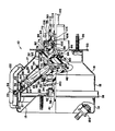
- the tandem brake booster 10 shown in the drawing has a housing 12 made of a front shell 14 and a rear shell 16 joined together by a twist lock connection 18.
- the front shell 14 has an integral end plate 15 with a conical section which is substantially parallel to integral end plate 17 on rear shell 16.
- the interior of the housing 12 is divided into a first chamber 20 whose limits are defined by the housing 12 and a first wall 24, a second chamber 26 whose limits are defined by the first wall 24, housing 12 and a second wall 28, and a third chamber 30 whose limits are defined by the second wall 28, housing 12 and a cylindrical projection 32 extending from the rear shell 16.
- the rear shell 16 is fixed to a stationary member 33 of a vehicle by a plurality of bolts 35.
- the first wall 24 includes a diaphragm 22, a backing plate 21 and a hub member 34.
- a first bead 23 on diaphragm 22 is retained by band 18 and a second bead 25 which is located in groove 27 on hub member 34 holds backing plate 21 against a shoulder 29.
- Hub member 34 has a cylindrical projection 38 that extends through an opening 40 in end plate 15.
- a push rod 41 connects projection 38 with a master cylinder, not shown.
- Hub member 34 has a central flange 42 with a plurality of slots 44, 44'... located therein for receiving ends 46, 46'... of lever arrangement 48 which connects the second wall 28 with the first wall 24.
- the second wall 28 includes a disc member 50, a diaphragm 52, and seal member 54.
- Diaphragm 52 has a first bead 56 that snaps over the end of disc member 50 and a second bead 58 is held against bead 23 by the connection 18.
- Fastener members 60 are attached to the disc member 50.
- Arms 62 of the lever arrangement 48 have one end 64 pivotally attached to fastener member 60 by pins 66.
- Projection 32 has a series of slots 68, only one of which is shown, with a lip 70 located at the bottom of each slot 68. Arms 62 engage lips 70 such that a fulcrum is produced in order to transfer force between the second wall 28 and central flange 42.
- a control mechanism 72 has a cylindrical body 74 with a seal 76 that engages projection 32 and an annular surface 78 that engages arms 62 between end 46, 46'... 46" and fulcrum lips 70.
- a bore 80 in the cylindrical body 74 has passages 82 and 84 that connect chamber 30 with chamber 26.
- a concentric cylindrical member 86 located in bore 80 has a seal 88 that engages bore 80 to extend passage 84 to an interior bore 90.
- Bore 90 is connected to passage 82 by passage 92.
- a reaction disc 94 is located between the bottom of bore 80 and the end of cylindrical member 86.
- a plunger 96 located in bore 90 has a series of slots 98 that provide for communication between passage 92 and vacuum seat 100. Plunger 96 has an atmospheric seat 102.
- a poppet valve 104 located in bore 90 has a first end 106 secured to cylindrical member 86 and a second end 108 that is free to move within bore 90.
- a first spring 110 acts on push rod 112 attached to plunger 96 to urge atmospheric seal 102 into engagement with free end 108.
- a second spring 114 located on piston rod 112 acts on the free end 108 to assist in establishing an atmospheric seal between plunger 96 and poppet 104.
- An internal combustion engine vacuum is produced at the intake manifold and as a result such vacuum is used in conjunction with air at atmospheric pressure as a motive force for operating many components of a vehicle.
- vacuum is communicated through check valve 120 into chamber 20.
- Vacuum in chamber 20 evacuates air from chamber 26 by way of passage 82, passage 92, bore 90, passage 84, chamber 30 and conduit 122.
- Movement of wall 28 which is in the opposite direction of movement of wall 24 causes lever arms 62 to pivot about fulcrum lip 70 and provide hub 34 with an additional or additive force to produce the operational force for push rod 41.
- the resistance to movement of push rod 41 produces a reaction force that is carried through annular surface 78 and into disc 94 to balance the input force applied to push rod 112. Since the annular surface 78 engages arms 62 at a position between fulcrum 70 and end 46, the movement of control member 72 as compared with the total movement of push rod 41 is equal to the ratio of the distance between end 46 and fulcrum 70 and between the annular surface 78 and fulcrum 70.
- the tandem brake booster 10 Depending on the desired operational force, with end plate 17 fixed to stationary support, and axial deflection force is produced in the tandem brake booster 10.
- the conical-shaped end members 15 and 17 tend to resist such axial deflection.
- the conical-shaped walls 24 and 28 nestle into the end member 15 and 17 to provide for a most efficient use of space.
- spring 110 On termination of the input force to push rod 112, spring 110 initially moves atmospheric seat 102 into engagement with free end 108 to interrupt communication of air to chamber 26. Further movement of plunger 96 by spring 110 moves free end 108 away from vacuum seat 100. With vacuum seat 100 opened, vacuum in chambers 30 and 20 evacuate air from chamber 26. As the pressure differential across walls 24 and 28 equalizes, spring 140 acts on hub member 34 to move wall 24 toward end plate 17. At the same time, a force acting on end 46 of lever 62 moves wall 28 toward end plate 15. When the fluid in chambers 20, 26, and 30 are equalized as shown in the drawing, cylindrical member 74 engages end plate 17 to limit the movement of walls 24 and 28 toward each other.
Landscapes
- Engineering & Computer Science (AREA)
- Transportation (AREA)
- Mechanical Engineering (AREA)
- Braking Systems And Boosters (AREA)
Claims (10)
Applications Claiming Priority (2)
| Application Number | Priority Date | Filing Date | Title |
|---|---|---|---|
| US529171 | 1983-09-02 | ||
| US06/529,171 US4475439A (en) | 1983-09-02 | 1983-09-02 | Tandem brake booster |
Publications (2)
| Publication Number | Publication Date |
|---|---|
| EP0143177A1 EP0143177A1 (de) | 1985-06-05 |
| EP0143177B1 true EP0143177B1 (de) | 1987-10-28 |
Family
ID=24108812
Family Applications (1)
| Application Number | Title | Priority Date | Filing Date |
|---|---|---|---|
| EP84109200A Expired EP0143177B1 (de) | 1983-09-02 | 1984-08-03 | Tandem-Servomotor |
Country Status (8)
| Country | Link |
|---|---|
| US (1) | US4475439A (de) |
| EP (1) | EP0143177B1 (de) |
| JP (1) | JPS6071363A (de) |
| AU (1) | AU568566B2 (de) |
| BR (1) | BR8404394A (de) |
| CA (1) | CA1229864A (de) |
| DE (1) | DE3466964D1 (de) |
| ES (1) | ES8505876A1 (de) |
Families Citing this family (7)
| Publication number | Priority date | Publication date | Assignee | Title |
|---|---|---|---|---|
| US4632015A (en) * | 1984-10-29 | 1986-12-30 | Allied Corporation | Tandem brake booster |
| US4649802A (en) * | 1984-10-29 | 1987-03-17 | Allied Corporation | Control valve |
| US4679491A (en) * | 1985-11-04 | 1987-07-14 | Allied Corporation | Reaction mechanism for tandem brake booster |
| US4672883A (en) * | 1985-12-02 | 1987-06-16 | Allied Corporation | Reaction mechanism for brake booster |
| KR20080025366A (ko) * | 2005-04-29 | 2008-03-20 | 텐딕스 디벨롭먼트, 엘엘씨 | 래디얼 임펄스 엔진, 펌프 및 압축기 시스템과 관련 동작방법 |
| US20100242891A1 (en) * | 2008-10-30 | 2010-09-30 | Timber Dick | Radial impulse engine, pump, and compressor systems, and associated methods of operation |
| KR102596574B1 (ko) * | 2021-11-16 | 2023-10-31 | 한국생산기술연구원 | 프레스 금형에서 펀치의 재연삭 시기를 실시간으로 결정하는 방법 및 장치 |
Family Cites Families (13)
| Publication number | Priority date | Publication date | Assignee | Title |
|---|---|---|---|---|
| US787421A (en) * | 1904-06-17 | 1905-04-18 | Leo Woerner | Fluid-pressure device. |
| US2042906A (en) * | 1935-07-23 | 1936-06-02 | Henry N Greis | Balanced pressure regulator |
| US3143929A (en) * | 1962-01-02 | 1964-08-11 | Bendix Corp | Full power fluid pressure servomotor construction |
| US3373662A (en) * | 1965-04-15 | 1968-03-19 | Gen Motors Corp | Zero travel vacuum suspended brake booster |
| FR1442138A (fr) * | 1965-08-05 | 1966-06-10 | Bendix Corp | Servomoteur à pression de fluide |
| US3411414A (en) * | 1966-06-27 | 1968-11-19 | Midland Ross Corp | Servomotor requiring minimum movement of actuator |
| DE2304834A1 (de) * | 1973-02-01 | 1974-08-08 | Felix Kaiser | Hebelanordnung zur verstaerkung von bremsgeraeten |
| GB1508613A (en) * | 1975-03-11 | 1978-04-26 | Automotive Prod Co Ltd | Fluid pressure servomotors |
| US4086842A (en) * | 1976-10-28 | 1978-05-02 | The Bendix Corporation | Internal force multiplier for a servomotor |
| US4148247A (en) * | 1977-05-31 | 1979-04-10 | General Motors Corporation | Dual power brake booster |
| JPS5746678Y2 (de) * | 1978-08-01 | 1982-10-14 | ||
| US4387626A (en) * | 1981-03-09 | 1983-06-14 | The Bendix Corporation | Tandem brake booster |
| DE3112343A1 (de) * | 1981-03-28 | 1982-10-14 | Alfred Teves Gmbh, 6000 Frankfurt | Bremskraftverstaerker fuer kraftfahrzeuge |
-
1983
- 1983-09-02 US US06/529,171 patent/US4475439A/en not_active Expired - Fee Related
-
1984
- 1984-08-03 DE DE8484109200T patent/DE3466964D1/de not_active Expired
- 1984-08-03 EP EP84109200A patent/EP0143177B1/de not_active Expired
- 1984-08-13 CA CA000460894A patent/CA1229864A/en not_active Expired
- 1984-08-23 AU AU32323/84A patent/AU568566B2/en not_active Ceased
- 1984-08-30 BR BR8404394A patent/BR8404394A/pt not_active IP Right Cessation
- 1984-08-31 ES ES535583A patent/ES8505876A1/es not_active Expired
- 1984-08-31 JP JP59180898A patent/JPS6071363A/ja active Pending
Also Published As
| Publication number | Publication date |
|---|---|
| ES535583A0 (es) | 1985-06-16 |
| DE3466964D1 (en) | 1987-12-03 |
| BR8404394A (pt) | 1985-07-30 |
| AU3232384A (en) | 1985-03-07 |
| JPS6071363A (ja) | 1985-04-23 |
| CA1229864A (en) | 1987-12-01 |
| AU568566B2 (en) | 1988-01-07 |
| ES8505876A1 (es) | 1985-06-16 |
| US4475439A (en) | 1984-10-09 |
| EP0143177A1 (de) | 1985-06-05 |
Similar Documents
| Publication | Publication Date | Title |
|---|---|---|
| US4069742A (en) | Power brake booster system | |
| US3972191A (en) | Balanced servomotor valve | |
| US4387626A (en) | Tandem brake booster | |
| EP0110740B1 (de) | Bremsbetätigungsaufbau | |
| US4487022A (en) | Brake actuator | |
| EP0143177B1 (de) | Tandem-Servomotor | |
| US4072014A (en) | Control means for a two stage servomotor | |
| US3442080A (en) | Dual hydraulic brake systems and brake booster mechanisms therefor | |
| US4475444A (en) | Brake apparatus | |
| US4553470A (en) | Assistor for reducing stepping force | |
| US3914941A (en) | Metering valve for proportioning an input force between concentric pistons | |
| US4571943A (en) | Tandem brake booster with hydraulic mechanism for rear diaphragm force reversal | |
| US4718327A (en) | Reaction mechanism for brake booster | |
| US4690034A (en) | Pneumatic booster | |
| CA1251252A (en) | Control valve | |
| US4754604A (en) | Hydraulic brake booster with tubular conduit return spring | |
| EP0143270B1 (de) | Bremsaufbau | |
| US4632015A (en) | Tandem brake booster | |
| US4672883A (en) | Reaction mechanism for brake booster | |
| US5848827A (en) | Braking assistance pneumatic servomotor with improved valve | |
| US3321917A (en) | Motor vehicle braking system | |
| US4679491A (en) | Reaction mechanism for tandem brake booster | |
| US4665800A (en) | Tandem brake booster | |
| GB2175660A (en) | Braking pressure generator | |
| CA1277694C (en) | Reaction mechanism for a tandem brake booster |
Legal Events
| Date | Code | Title | Description |
|---|---|---|---|
| PUAI | Public reference made under article 153(3) epc to a published international application that has entered the european phase |
Free format text: ORIGINAL CODE: 0009012 |
|
| AK | Designated contracting states |
Designated state(s): DE FR GB IT |
|
| 17P | Request for examination filed |
Effective date: 19851121 |
|
| 17Q | First examination report despatched |
Effective date: 19860807 |
|
| RAP1 | Party data changed (applicant data changed or rights of an application transferred) |
Owner name: ALLIED CORPORATION |
|
| ITF | It: translation for a ep patent filed | ||
| GRAA | (expected) grant |
Free format text: ORIGINAL CODE: 0009210 |
|
| AK | Designated contracting states |
Kind code of ref document: B1 Designated state(s): DE FR GB IT |
|
| REF | Corresponds to: |
Ref document number: 3466964 Country of ref document: DE Date of ref document: 19871203 |
|
| ET | Fr: translation filed | ||
| PLBE | No opposition filed within time limit |
Free format text: ORIGINAL CODE: 0009261 |
|
| STAA | Information on the status of an ep patent application or granted ep patent |
Free format text: STATUS: NO OPPOSITION FILED WITHIN TIME LIMIT |
|
| 26N | No opposition filed | ||
| PGFP | Annual fee paid to national office [announced via postgrant information from national office to epo] |
Ref country code: GB Payment date: 19900720 Year of fee payment: 7 |
|
| PGFP | Annual fee paid to national office [announced via postgrant information from national office to epo] |
Ref country code: FR Payment date: 19900807 Year of fee payment: 7 |
|
| ITTA | It: last paid annual fee | ||
| PGFP | Annual fee paid to national office [announced via postgrant information from national office to epo] |
Ref country code: DE Payment date: 19900927 Year of fee payment: 7 |
|
| PG25 | Lapsed in a contracting state [announced via postgrant information from national office to epo] |
Ref country code: GB Effective date: 19910803 |
|
| GBPC | Gb: european patent ceased through non-payment of renewal fee | ||
| PG25 | Lapsed in a contracting state [announced via postgrant information from national office to epo] |
Ref country code: FR Effective date: 19920430 |
|
| PG25 | Lapsed in a contracting state [announced via postgrant information from national office to epo] |
Ref country code: DE Effective date: 19920501 |
|
| REG | Reference to a national code |
Ref country code: FR Ref legal event code: ST |