EP0143183A2 - Dispenser for active materials - Google Patents
Dispenser for active materials Download PDFInfo
- Publication number
- EP0143183A2 EP0143183A2 EP84109706A EP84109706A EP0143183A2 EP 0143183 A2 EP0143183 A2 EP 0143183A2 EP 84109706 A EP84109706 A EP 84109706A EP 84109706 A EP84109706 A EP 84109706A EP 0143183 A2 EP0143183 A2 EP 0143183A2
- Authority
- EP
- European Patent Office
- Prior art keywords
- piston
- pump
- cylinder
- dispenser
- storage space
- Prior art date
- Legal status (The legal status is an assumption and is not a legal conclusion. Google has not performed a legal analysis and makes no representation as to the accuracy of the status listed.)
- Granted
Links
- 239000011149 active material Substances 0.000 title 1
- 239000013543 active substance Substances 0.000 claims description 40
- 239000004480 active ingredient Substances 0.000 claims description 15
- 210000002445 nipple Anatomy 0.000 claims description 14
- 230000006835 compression Effects 0.000 claims description 12
- 238000007906 compression Methods 0.000 claims description 12
- 230000007423 decrease Effects 0.000 claims description 3
- 238000007789 sealing Methods 0.000 claims description 2
- 230000002093 peripheral effect Effects 0.000 claims 1
- 238000005086 pumping Methods 0.000 description 7
- 230000002349 favourable effect Effects 0.000 description 3
- 239000003795 chemical substances by application Substances 0.000 description 2
- 230000009194 climbing Effects 0.000 description 2
- QVGXLLKOCUKJST-UHFFFAOYSA-N atomic oxygen Chemical compound [O] QVGXLLKOCUKJST-UHFFFAOYSA-N 0.000 description 1
- 238000000889 atomisation Methods 0.000 description 1
- 230000003247 decreasing effect Effects 0.000 description 1
- 238000007599 discharging Methods 0.000 description 1
- 238000006073 displacement reaction Methods 0.000 description 1
- 229940079593 drug Drugs 0.000 description 1
- 239000003814 drug Substances 0.000 description 1
- 230000000694 effects Effects 0.000 description 1
- 239000013013 elastic material Substances 0.000 description 1
- 239000007788 liquid Substances 0.000 description 1
- 238000004519 manufacturing process Methods 0.000 description 1
- 229910052760 oxygen Inorganic materials 0.000 description 1
- 239000001301 oxygen Substances 0.000 description 1
- 235000011837 pasties Nutrition 0.000 description 1
- 230000037452 priming Effects 0.000 description 1
- 230000000069 prophylactic effect Effects 0.000 description 1
- 238000004904 shortening Methods 0.000 description 1
- 230000001225 therapeutic effect Effects 0.000 description 1
- 229940034610 toothpaste Drugs 0.000 description 1
- 239000000606 toothpaste Substances 0.000 description 1
Images

Classifications
-
- B—PERFORMING OPERATIONS; TRANSPORTING
- B65—CONVEYING; PACKING; STORING; HANDLING THIN OR FILAMENTARY MATERIAL
- B65D—CONTAINERS FOR STORAGE OR TRANSPORT OF ARTICLES OR MATERIALS, e.g. BAGS, BARRELS, BOTTLES, BOXES, CANS, CARTONS, CRATES, DRUMS, JARS, TANKS, HOPPERS, FORWARDING CONTAINERS; ACCESSORIES, CLOSURES, OR FITTINGS THEREFOR; PACKAGING ELEMENTS; PACKAGES
- B65D83/00—Containers or packages with special means for dispensing contents
- B65D83/76—Containers or packages with special means for dispensing contents for dispensing fluent contents by means of a piston
- B65D83/765—Containers or packages with special means for dispensing contents for dispensing fluent contents by means of a piston the piston being a follower-piston and the dispensing means comprising a hand-operated pressure device at the opposite part of the container
-
- B—PERFORMING OPERATIONS; TRANSPORTING
- B05—SPRAYING OR ATOMISING IN GENERAL; APPLYING FLUENT MATERIALS TO SURFACES, IN GENERAL
- B05B—SPRAYING APPARATUS; ATOMISING APPARATUS; NOZZLES
- B05B11/00—Single-unit hand-held apparatus in which flow of contents is produced by the muscular force of the operator at the moment of use
- B05B11/01—Single-unit hand-held apparatus in which flow of contents is produced by the muscular force of the operator at the moment of use characterised by the means producing the flow
- B05B11/02—Membranes or pistons acting on the contents inside the container, e.g. follower pistons
- B05B11/028—Pistons separating the content remaining in the container from the atmospheric air to compensate underpressure inside the container
-
- B—PERFORMING OPERATIONS; TRANSPORTING
- B05—SPRAYING OR ATOMISING IN GENERAL; APPLYING FLUENT MATERIALS TO SURFACES, IN GENERAL
- B05B—SPRAYING APPARATUS; ATOMISING APPARATUS; NOZZLES
- B05B11/00—Single-unit hand-held apparatus in which flow of contents is produced by the muscular force of the operator at the moment of use
- B05B11/01—Single-unit hand-held apparatus in which flow of contents is produced by the muscular force of the operator at the moment of use characterised by the means producing the flow
- B05B11/10—Pump arrangements for transferring the contents from the container to a pump chamber by a sucking effect and forcing the contents out through the dispensing nozzle
- B05B11/1001—Piston pumps
- B05B11/1004—Piston pumps comprising a movable cylinder and a stationary piston
-
- B—PERFORMING OPERATIONS; TRANSPORTING
- B05—SPRAYING OR ATOMISING IN GENERAL; APPLYING FLUENT MATERIALS TO SURFACES, IN GENERAL
- B05B—SPRAYING APPARATUS; ATOMISING APPARATUS; NOZZLES
- B05B11/00—Single-unit hand-held apparatus in which flow of contents is produced by the muscular force of the operator at the moment of use
- B05B11/01—Single-unit hand-held apparatus in which flow of contents is produced by the muscular force of the operator at the moment of use characterised by the means producing the flow
- B05B11/10—Pump arrangements for transferring the contents from the container to a pump chamber by a sucking effect and forcing the contents out through the dispensing nozzle
- B05B11/1042—Components or details
- B05B11/1066—Pump inlet valves
- B05B11/107—Gate valves; Sliding valves
-
- B—PERFORMING OPERATIONS; TRANSPORTING
- B05—SPRAYING OR ATOMISING IN GENERAL; APPLYING FLUENT MATERIALS TO SURFACES, IN GENERAL
- B05B—SPRAYING APPARATUS; ATOMISING APPARATUS; NOZZLES
- B05B11/00—Single-unit hand-held apparatus in which flow of contents is produced by the muscular force of the operator at the moment of use
- B05B11/01—Single-unit hand-held apparatus in which flow of contents is produced by the muscular force of the operator at the moment of use characterised by the means producing the flow
- B05B11/10—Pump arrangements for transferring the contents from the container to a pump chamber by a sucking effect and forcing the contents out through the dispensing nozzle
- B05B11/1042—Components or details
- B05B11/1073—Springs
- B05B11/1074—Springs located outside pump chambers
-
- B—PERFORMING OPERATIONS; TRANSPORTING
- B05—SPRAYING OR ATOMISING IN GENERAL; APPLYING FLUENT MATERIALS TO SURFACES, IN GENERAL
- B05B—SPRAYING APPARATUS; ATOMISING APPARATUS; NOZZLES
- B05B11/00—Single-unit hand-held apparatus in which flow of contents is produced by the muscular force of the operator at the moment of use
- B05B11/01—Single-unit hand-held apparatus in which flow of contents is produced by the muscular force of the operator at the moment of use characterised by the means producing the flow
- B05B11/10—Pump arrangements for transferring the contents from the container to a pump chamber by a sucking effect and forcing the contents out through the dispensing nozzle
- B05B11/1042—Components or details
- B05B11/1073—Springs
- B05B11/1077—Springs characterised by a particular shape or material
Definitions
- the invention relates to an active substance dispenser with a storage container, a sliding piston which can be displaced therein and which seals the storage space at one end and a piston pump which is provided on the opposite end of the container and is connected on the outlet side to an active substance discharge opening, the pump cylinder receiving a sliding pump piston on the inlet side is connected to the pantry.
- Known active ingredient dispensers of this type are generally used for pasty active ingredients, for example toothpaste.
- the known dispensers are not suitable for atomizing, for example, low-viscosity active substances, such as medical therapeutic and prophylactic active substances or the like. They are also relatively difficult to operate and the discharge pressure is relatively low.
- the invention has for its object to provide an active ingredient dispenser of the type mentioned, in which guidance of the active substance which is as linear as possible from the storage space to the vicinity of the discharge opening, favorable flow conditions and thus high discharge pressures can be achieved, so that the dispenser can also be used for those active substances which are to be atomized during discharge.
- an active substance dispenser of the type described at the outset according to the invention in that the pump cylinder of the piston pump lies essentially axially parallel to the trailing piston.
- the pump cylinder is expediently of the type that its end remote from the storage space, only closed by the pump piston and otherwise open end forms the outlet opening of the pump cylinder for the active substance, while the inner end correspondingly forms the inlet opening to the storage space.
- the pump cylinder is arranged coaxially with the trailing piston and in particular protrudes into the storage space and preferably has a suction nozzle which is also coaxial with the pump piston as the end section projecting furthest into the storage space.
- the active ingredient is taken over deeply from the storage space by the pump cylinder, so that the active ingredient has to carry out only very slight internal flow movements within the storage space.
- the suction port is overhung in the storage room.
- a particularly advantageous development of the subject matter of the invention is that an axially biased outlet valve, mechanically positively opened at the end of the piston stroke, is provided in the conduit path between the pump piston and the discharge opening, the closing part of which is preferably formed by an elastic compression sleeve, the outer end of which is attached to one Piston shaft attached and in particular forms the annular piston with the inner end adjacent to the annular closing part.
- This makes it possible to put the active substance in the pump cylinder under increased pressure during the pump stroke of the pump piston without the active substance already escaping, after which the active substance compressed in this way is suddenly released and exits at the associated end of the pump cylinder by mechanical opening of the outlet valve.
- this also makes it possible to design the dispenser in such a way that the active substance inside the dispenser can under no circumstances come into contact with air, which is of great importance for some medicinal active substances.
- the last-mentioned advantages are further improved in that the pump piston abuts a stop shoulder at the end of the piston stroke and that the piston shaft can be moved beyond the stop position of the pump piston by opening the exhaust valve.
- the annular closing part of the outlet valve has a valve closing surface which is located on the inner circumferential surface and is associated with the piston skirt, and an abutment surface which is located on the outer circumference and which, when reset Pump piston with prestress sealingly rests on a counter shoulder of the pump cylinder.
- the outlet valve is mechanically positively closed when the pump piston is reset.
- the pump cylinder is also hermetically sealed to the storage space when the pump piston is reset.
- the valve closing pressure of the According to the invention, the outlet valve is higher than the maximum pressure in the storage space, so that under no circumstances can active ingredient escape from the dispenser unintentionally, that is to say without actuating the pump.
- the trailing piston is cup-shaped to the piston pump open hollow and that the inner cross sections of the trailing piston are essentially exactly adapted to the, in particular stepped tapered, outer shape of the portion of the piston pump protruding into the reservoir, such that this section fills the cavity of the trailing piston when the storage space is empty.
- the dispenser according to the invention also makes it possible to meter the amount of active substance applied per piston stroke very precisely, even if this amount is very small, for example in the order of a few hundredths of a cubic centimeter.
- This precise, repeatable metering of the amount of active substance applied with a simple structure of the dispenser is achieved in a further embodiment even when the pump piston towards the end of the return stroke in the manner of a slot control releases a connection opening between the storage space, which can be changed in volume to maintain full filling with the active substance supply quantity, and is sealed in a vacuum-tight manner, and the pump space and if the part of the pump space lying between the pump end position of the pump piston and the connection opening is provided as a metering space whose connecting opening is immersed in this vacuum-tight storage space at least in its release position, the connecting opening preferably being formed by the open end of the pump cylinder, by means of which the pump piston is completely moved out of the pump cylinder towards the end of the return stroke, and in particular a funnel-shaped in
- the pump chamber can only and only be filled with the active substance during the return stroke of the pump piston with maximum utilization of the resulting negative pressure, which is a prerequisite that a precisely defined, that is precisely metered amount always gets repeatedly into the pump chamber during the return stroke , which is then discharged through the outlet opening during the pump stroke.
- the metered quantity can be precisely determined with the size of the part of the pump chamber provided as the metering chamber. Nevertheless, this amount can be repeatedly applied in quick succession.
- this design ensures that the lowest possible flow resistances occur when the active substance is sucked into the pump chamber, the size of the connection opening corresponding to the inner cross section of the pump cylinder, which accommodates a sudden suction of the active substance after the connection opening has been released; due to the funnel-shaped inlet surface, the flow resistances that occur are further reduced.
- connection opening is preferably closed on part of the return stroke of the pre-suction piston and / or the piston sealing surface of the pre-suction piston is provided at the free end of the intermediate cylinder.
- a structurally simple embodiment is achieved if the pump piston is arranged fixedly with respect to the intermediate cylinder, in particular approximately coaxially in the intermediate cylinder, and preferably at least one outlet opening to the storage space is provided between the outer circumference of the pump piston and the inner circumference of the intermediate cylinder Achieving favorable flow conditions is expediently greater than that of the connection opening.
- the design according to the invention also makes it possible to provide an arrangement in which the metered discharge amount can be changed in a precisely defined manner if necessary.
- This can be achieved in a simple manner, for example, by the volume of the metering chamber being made variable, the end wall of the pump cylinder opposite the pump piston, for example with an outlet sleeve guided in an actuating thread of the cylinder wall of the pump cylinder, being axially adjustable and guided, for example, by self-locking .
- the pump stroke of the thrust piston pump is limited by the pump piston striking the opposite end wall of the pump cylinder.
- the pump piston is spring-loaded to the starting position and is limited in the starting position, preferably the pump cylinder being movably mounted with a handle, for example a container cap receiving a return spring and covering the pump.
- the return spring can also be designed as a resilient element which is integral with at least one of the two components which can be moved relative to one another and in particular can be formed by bulging guide arms of the handle which are loaded with buckling.
- the pump piston therefore forms a unit that is structurally combined with the storage container and is fixed relative to it, while the cylinder and optionally the pre-suction piston represent the parts that have to be moved by hand during the pump stroke, resulting in a structurally very simple configuration of the dispenser.
- an outlet valve is designed as a check valve, which preferably has at least one circumference an outlet opening provided with an outlet nipple and, as a valve closing part, a valve stocking elastically surrounding the outlet nipple, the free end of which, for example, forms the outlet opening. This also ensures that the outlet valve closes very quickly and tightly at the end of the active substance discharge or at the beginning of the return stroke and maintains this vacuum-tight seal securely until the metering space is filled again or until the next pump stroke.
- This advantage is further improved if the design of the dispenser is further simplified if all essential parts of the dispenser are arranged in a common axis and are expediently axially symmetrical; this applies in particular to the pump cylinder, the storage space, the outlet opening, the intermediate cylinder and the handle.
- the cross section of the dispenser can be round, in particular circular, polygonal or different.
- an active substance dispenser has a storage container 2, which is designed, for example, as a standing vessel, and a thrust piston pump 1 arranged thereon at the same time as a closure cap, which is provided, for example, on the upper end opposite the standing surface of the storage container 2.
- the push piston pump 1 of which essential parts or the parts which are fixed in position relative to the storage container 2 are formed integrally therewith, has a cylinder 3 which is movable in the longitudinal direction of the storage container 2 relative to the latter via more than the pump stroke and which has a position fixed on the storage container 2 arranged pump piston 4 is assigned.
- the cylinder 3 is in turn formed at its free end as a pre-suction piston 5 which is guided in an intermediate cylinder 6 surrounding the pump piston 4 at a distance.
- This intermediate cylinder 6 forms the most provided end of the neck of the storage container 2, both the inner cross sections of the intermediate cylinder 6 and that of the cylinder 3 being smaller than those of the storage container 2.
- the intermediate cylinder 6 extends to the associated end wall 7 of the, for example, continuously cylindrical storage container 2 and, with its free end, projects further than the pump piston 4 located in it, which is thus provided entirely within the intermediate cylinder 6.
- the pumping piston 4 is arranged on a piston-shaped piston shaft 8, as seen in its axial direction, as a result of which four outlet openings 9 are formed between the inside of the storage container 2 and the cylinder space 10 of the intermediate cylinder 6, which lie approximately in the plane of the end wall 7.
- the priming piston 5 can be moved approximately to the free end of the intermediate cylinder 6 so that the pump piston 4 has been completely moved out of the open end of the cylinder 3 for about the last third of the return stroke, in such a way that its front opening facing the pump piston 4 opens into the cylinder chamber 10 forms open connection opening 11 which can be closed by pump piston 4 in the manner of a slot control.
- This connection opening 11 is essentially delimited by the narrower end of a funnel or truncated cone-shaped inlet surface 12 for the pump piston 4, the narrower end of which connects directly to the piston race 13 of the cylinder 3 and the other end of which is larger than the piston cross-section;
- the inlet surface 12 has a taper angle of approximately 90 °.
- cylindrical piston race 13 limits that part of the pump chamber of the push piston pump 1 which is provided as a metering chamber 15, since the pump piston 4 at least approximately at the end of the pump stroke on the ring shoulder-shaped end face 14 of the piston running surface 13 abuts.
- the cylinder 3 is structurally or integrally united with an outlet nipple 16 which, with the interposition of an outlet valve 17 designed as a check valve, connects the metering chamber 15 to an outlet opening 18 for the active substance.
- This line connection 19 is relatively short and essentially rectilinear, decreasing in cross-section to the check valve 17 and widening again between the check valve 17 and the outlet opening 18.
- the line connection 19 is formed by a first section, which is axially identical to the metering chamber 15 and has a reduced cross section compared to the metering chamber 15, an adjoining, further reduced cross section and likewise lying in the axis of the metering chamber 15, and two or more radially in these opening openings formed in the outlet nipple 16, these outlet openings 20 simultaneously forming the valve openings of the outlet valve 17.
- the outlet valve 17 has an elastic valve stocking which surrounds the entire length of the outlet nipple 16 and is secured against axial displacement, which surrounds the outlet nipple 16 in the region of the outlet openings 20 lying on its periphery and tightly over the end of the outlet nipple 16 in such a way protrudes that it directly forms with its end the outlet opening 18, the opening cross section of which is therefore essentially equal to the largest cross section of the outlet nipple 16.
- the cylinder 3 and the outlet nipple 16 are provided on the end wall 23 of a handle 27, which is perpendicular to the central axis of the dispenser, and are formed integrally therewith.
- This handle 22 has several, in the illustrated embodiment four j, evenly distributed over the circumference, to the dispenser 8 parallel guide arms 24, which surround the storage container 2 on the circumference at a short distance and are provided at their ends with inwardly directed cams 25, which as the return stroke limiting stop 26 is associated with a projecting over the outer circumference of the storage container 2 ring collar.
- a return spring 27 is provided within the guide arms 24 as a return spring 27 which is supported on the one hand on the inside of the end wall 23 and on the other hand on the stop 26 and surrounds the reservoir 2 over the circumference over part of its length.
- a return spring 27 is also conceivable to fasten the ends of the guide arms 24 facing away from the end wall 23, for example by one-piece manufacture, to the storage container 2 and to design them with regard to their elasticity and strength so that they themselves act as return springs in such a way that they come out of them during the pump stroke stretched position are arched resiliently outward.
- the trailing piston 29 is freely movable along its cylinder track with relatively little friction, the storage container 2 being open on the side of the piston 29 remote from the storage space 28 or provided with a pressure compensation opening so that the piston 29 on this side no negative pressure can arise.
- the storage space 28 including the cylinder space 10, the metering space 15 and the line connection 19 is completely filled with the active ingredient to be metered out and the cylinder 3 is under the force of the return spring 27 at the end of its return stroke. If the cylinder 3 is now moved in the direction of the pump piston 4 counter to the force of the return spring 27, part of the amount of active substance located in the cylinder chamber 10 is first displaced in the direction of the storage chamber 28 until the pump piston 4 along the inlet surface 12 begins has reached the piston track 13 of the metering chamber 15 and thereby closed it; the closing voltage of the exhaust valve 17 is chosen so large that it does not open until this moment. Therefore, the climbing piston is pushed back in this phase and, if it is relatively stuck, loosened.
- the amount of active substance in the metering chamber 15 is pressurized by the pump piston 4, whereby the outlet valve 17 according to FIG. 2 opens, so that the metered amount of active substance exits via the line connection 19 at the outlet opening 18.
- the total stroke is, for example, only 5 mm and the storage container 2 of the dispenser shown enlarged in FIGS. 1 to 5 holds, for example, only about four cubic centimeters.
- the outlet valve 17 closes again automatically due to the elastic tension of the valve closing part 21.
- the cylinder 3 according to FIG. 3 is moved back to its starting position under the force of the return spring 27 .
- the pre-suction piston 5 moves back in the intermediate cylinder 6, as is the case for the pump piston 4 and the cylinder 3. Due to the negative pressure that occurs in the intermediate cylinder 6, active substance is sucked into the intermediate cylinder 6 from the storage space 28.
- the connection opening 11 is suddenly released during the further return stroke movement, the maximum possible negative pressure being reached at this moment by the return stroke movement of the pump piston 4 in the metering chamber 15.
- connection opening 11 As soon as the connection opening 11 is opened, the active ingredient sucked into the intermediate cylinder 6 is sucked suddenly into the metering chamber 15 with complete filling.
- the cylinder space 10 thus belongs to the storage space 28, in which the connection opening 11 is completely immersed during the return stroke.
- the climbing piston 29 is trailed by the underpressure which arises in the storage space 28 by a distance corresponding to the metered quantity, such that the storage space 28 decreases in volume but always remains completely filled.
- the push piston pump 1a according to FIG. 6 is designed to be removable from the storage container 2a in such a way that it can be refilled with active substance through its container neck 31.
- the pump piston 4a and the intermediate cylinder 6a are structurally combined with a screw sleeve 7a, which can be detachably screwed onto an external thread of the container neck 31 and forms a vacuum-tight seal.
- the handle 22a is in this case directly limited in terms of its return stroke with respect to the screw sleeve 7a.
- the outlet nipple in the embodiment according to FIG. 6 is formed by an outlet sleeve 16a which is provided with an external thread with which it is adjustable in the direction of the pump stroke in an adjusting thread 30 provided in the cylinder wall 13a of the pump cylinder 3a and can be locked by self-locking.
- This outlet sleeve 16a forms with its inner end the end wall 14a of the metering chamber 15a opposite the pump piston 4a, so that the size of the metering chamber 15a and thus the amount of active ingredient to be metered out can be changed by adjusting the outlet sleeve 16a.
- the active ingredient dispenser according to the invention is particularly suitable, for example, for the metered delivery of active ingredients for inhalation devices or as a drip dispenser, which can be designed for an exact number of liquid drops to be dispensed per pump stroke. However, it can also be used for other media than drugs.
- the active substance dispenser according to FIGS. 7 and 8 has as a pump a manually operated piston pump 1b, which is fastened with a gasket 32 with a sleeve-shaped housing part 33 to the end face of the neck 31b of the container 2b by means of a clamping ring and with all parts are aligned with the container 2b.
- the cylinder 3b On the housing part 33, which is designed in the manner of two coaxially nested sleeves and merges with one another on the outer end face, the cylinder 3b is fastened with its outer end section which engages positively between the two sleeves of the housing part 33 in such a way that it surrounds the inner circumference of the neck 31b with a small gap distance and protrudes relatively deep into the storage space 28b with a suction nozzle 34 forming its inner tapered end.
- the cylinder 3b forms a piston raceway 13b for the piston 4b approximately in the region of the neck 31b, which is formed by an inner end section of a sleeve-shaped component made of rubber-elastic material.
- the piston 4b which is widened in the shape of a truncated cone in the direction of the pump stroke and tapered uniformly in its wall thickness, merges in one piece at its rear end into an annular closing part 21b of an outlet valve 17b, which in turn on the side facing away from the piston 4b into a spring that can be shortened by axial pressure Compression sleeve 35 passes over.
- the compression sleeve 35 forms a flange ring 36 which is formed in one piece with the piston 4b and which is fastened in an end groove of the piston shaft 8b.
- the compression sleeve 35 is convexly curved on the outside in cross-section, this curvature increasing with compression or shortening of the compression sleeve 35.
- the sleeve-shaped elastic component is tightly closed between the annular lip-like piston seal 37 provided at the free end of the piston 4b, which is formed directly by the piston and lies closely against the piston raceway 13b, and the fastening of the flange ring 36 in the piston shaft 8b.
- the piston shaft 8b which forms the associated section of the line connection 19b between the cylinder space 10b and the discharge opening 18b in its interior, consists of two parts, namely an outer sleeve-shaped part 38 and a plunger 39 which extends over part of the length of the sleeve-shaped part 38 thereof The inside or the end facing the container 2b engages, leaving the line connection free.
- the end groove is provided for receiving the flange ring 36.
- the plunger 39 has in the area of the closing part 21b an annular collar projecting over its circumference, the end face of which, at an obtuse angle to the suction port 34 and which faces away from the suction port 34, forms one of the two closing surfaces, namely the closing surface 40 of the outlet valve 17b.
- the closing part 21b forms on its inner circumference the other valve closing surface 41, which is adapted to the closing surface 40 and which, when the pump is in the initial position, bears against the closing surface 40 with a relatively high closing pressure under the force of the compression sleeve 35 serving as a valve closing spring.
- the inner sleeve 6b of the housing part 33 which engages in the rear open end of the cylinder 3b, forms, with its free end lying in the cylinder 3b, a counter shoulder 26b for an annular shoulder-shaped stop surface 22 provided on the outer circumference of the closing part 21b, which in cross section is frustoconical in shape to the suction nozzle 34 is expanded.
- the abutment surface 42 runs onto the counter shoulder 26b, as a result of which the compression sleeve 35 is slightly stretched and the closing part 21b of the outlet valve 17b is inevitably both axially pressed against the closing surface 40 and also biased radially to the axis of the outlet valve 17b that an extremely tight and secure closure of the outlet valve 17b is guaranteed.
- the cylinder 3b is structurally combined with the housing part 33 so that when the piston 4b is in the initial position, an annular space 43 is provided on the outside thereof, which is located between the piston seal 37 and the valve-like seal which is created by the abutment of the counter shoulder 26b on the stop surface 42 is formed.
- the piston raceway 13b merges into a stop shoulder 14b projecting inwardly in an annular manner, onto which the free end face of the piston 4b runs at the end of the pump stroke according to FIG. 8.
- the piston shaft 8b can be moved a small distance in the direction of the pump stroke, so that the closing surface 40 then lifts from the valve closing surface 41 and an annular one between these surfaces Passage opening 20b of the outlet valve 17b is released.
- the compression sleeve 35 is elastically compressed and thereby shortened.
- a sleeve-shaped connecting nipple 16b is placed with a plug connection, which forms an integral component with a cap-like handle 22b surrounding it and is arranged with an outer sleeve on the end wall 23b thereof.
- the discharge opening 18b designed as an atomizer opening is provided.
- the trailing piston 29b has an outer piston ring with two annular, sealed lips provided at both ends and a fitting sleeve 45 located therein, which with its open end facing the piston pump 1b merges in one piece and tightly into the piston ring 29b.
- the inner cross sections of the fitting sleeve 45 lying axially aligned with the section of the piston pump 1b projecting over the end wall 7b of the container 2b into the storage space 28b, the cup sleeve 45 being closed at its end remote from the piston pump 1b and projecting beyond the associated end of the piston ring are so adapted to the outer shape of the above-mentioned section of the piston pump 1b that in the end position of the trailing piston 29b associated with the emptied storage space 28b, the projecting section of the piston pump 1b fills the interior of the adapter sleeve 45 almost completely without gaps and the free end of the suction port 34 abuts the bottom wall of the fitting sleeve 45. In this position, the associated end
- the product to be atomized that is to say the active substance, does not come into contact with oxygen before the discharge, since at no point in time during the application is there a connecting channel between the container and the outside air.
- the atomization or discharge can also take place in any position of the dispenser, for example in an upside-down position, since active substance is always present on the suction nozzle 34.
Landscapes
- Engineering & Computer Science (AREA)
- Mechanical Engineering (AREA)
- Containers And Packaging Bodies Having A Special Means To Remove Contents (AREA)
- Reciprocating Pumps (AREA)
Abstract
Ein vakuum- und druckdicht geschlossener Vorratsraum (28b) in einem Behälter (2b) ist mit einer in ihn ragenden Schubkolbenpumpe (1b) und einem in ihm gleitbar geführten Schleppkolben (29b) baulich vereint und bei Ausgangslage der Schubkolbenpumpe (1b) durch ein mechanisch zwangsgesteuert geschlossenes Auslaßventil (17b) hermetisch verschlossen. Der Schleppkolben (29b) ist so an die Schubkolbenpumpe (1b) angepaßt, daß der Vorratsraum (28b) im wesentlichen recht frei mit der Schubkolbenpumpe (1b) entleert werden kann.A vacuum and pressure-tight closed storage space (28b) in a container (2b) is structurally combined with a thrust piston pump (1b) projecting into it and a trailing piston (29b) slidably guided in it and, in the starting position of the thrust piston pump (1b), mechanically positively controlled closed outlet valve (17b) hermetically sealed. The trailing piston (29b) is adapted to the push piston pump (1b) in such a way that the storage space (28b) can be emptied essentially freely with the push piston pump (1b).
Description
Die Erfindung betrifft einen Wirkstoff-Spender mit einem Vorrtasbehälter, einem darin verschiebbaren, den Vorratsraum an einem Ende dicht verschließenden Schleppkolben und einer an dem diesem gegenüberliegenden Behälterende vorgesehenen, auslaßseitig mit einer Wirkstoff-Austragöffnung verbundenen Kolbenpumpe, deren, einen verschiebbaren Pumpkolben aufnehmender, Pumpenzylinder eingangsseitig an den Vorratsraum angeschlossen ist.The invention relates to an active substance dispenser with a storage container, a sliding piston which can be displaced therein and which seals the storage space at one end and a piston pump which is provided on the opposite end of the container and is connected on the outlet side to an active substance discharge opening, the pump cylinder receiving a sliding pump piston on the inlet side is connected to the pantry.
Bekannte Wirkstoff-Spender dieser Art werden in der Regel für pastöse Wirkstoffe, beispielsweise Zahnpasta verwendet. Für zu zerstäubende, beispielsweise dünnflüssige Wirkstoffe, wie medizinische Therapie- und Prophylaxe-Wirkstoffe oder dergl. sind die bekannten Spender nicht geeignet. Sie sind darüber hinaus relativ schwer zu betätigen und der Austragdruck ist relativ gering.Known active ingredient dispensers of this type are generally used for pasty active ingredients, for example toothpaste. The known dispensers are not suitable for atomizing, for example, low-viscosity active substances, such as medical therapeutic and prophylactic active substances or the like. They are also relatively difficult to operate and the discharge pressure is relatively low.
Der Erfindung liegt die Aufgabe zugrunde einen Wirkstoff-Spender der genannten Art zu schaffen, bei welchem durch möglichst lineare Führung des Wirkstoffes vom Vorratsraum bis in die Nähe der Austragöffnung günstige Strömungsverhältnisse und damit hohe Austragdrücke erzielt werden können, so daß der Spender auch für solche Wirkstoffe eingesetzt werden kann, die beim Austrag zerstäubt werden sollen.The invention has for its object to provide an active ingredient dispenser of the type mentioned, in which guidance of the active substance which is as linear as possible from the storage space to the vicinity of the discharge opening, favorable flow conditions and thus high discharge pressures can be achieved, so that the dispenser can also be used for those active substances which are to be atomized during discharge.
Diese Aufgabe wird bei einem Wirkstoff-Spender der eingangs beschriebenen Art gemäß der Erfindung dadurch gelöst, daß der Pumpenzylinder der Kolbenpumpe im wesentlichen achsparallel zum Schleppkolben liegt. Der Pumpenzylinder ist dabei zweckmäßig von der Art, daß sein vom Vorratsraum abgekehrtes, lediglich vom Pumpkolben geschlossenes und ansonsten offenes Ende die Auslaßöffnung des Pumpemzylinders für den Wirkstoff bildet, während das innere Ende entsprechend die Einlaßöffnung zum Vorratsraum hin bildet.This object is achieved in an active substance dispenser of the type described at the outset according to the invention in that the pump cylinder of the piston pump lies essentially axially parallel to the trailing piston. The pump cylinder is expediently of the type that its end remote from the storage space, only closed by the pump piston and otherwise open end forms the outlet opening of the pump cylinder for the active substance, while the inner end correspondingly forms the inlet opening to the storage space.
Räumlich besonders günstige Verhältnisse werden erzielt, wenn der Pumpenzylinder achsgleich zum Schleppkolben und insbesondere in den Vorratsraum ragend angeordnet ist und vorzugsweise einen ebenfalls zum Pumpkolben achsgleichen Saugstutzen als am weitesten in den Vorratsraum ragenden Endabschnitt aufweist. Dadurch wird der Wirkstoff vom Pumpenzylinder tief aus dem Vorratsraum übernommen, so daß der Wirkstoff innerhalb des Vorratsraumes nur sehr geringe innere Strömungsbewegungen ausführen muß. Der Saugstutzen liegt fliegend im Vorratsraum.Spatially particularly favorable conditions are achieved if the pump cylinder is arranged coaxially with the trailing piston and in particular protrudes into the storage space and preferably has a suction nozzle which is also coaxial with the pump piston as the end section projecting furthest into the storage space. As a result, the active ingredient is taken over deeply from the storage space by the pump cylinder, so that the active ingredient has to carry out only very slight internal flow movements within the storage space. The suction port is overhung in the storage room.
Eine besonders vorteilhafte Weiterbildung des Erfindungsgegenstandes besteht darin, daß im Leitungsweg zwischen dem Pumpkolben und der Austragöffnung ein axial vorgespanntes, am Ende des Kolbenhubes mechanisch zwangsgesteuert geöffnetes Auslaßventil vorgesehen ist, dessen Schließteil vorzugsweise durch eine elastische Stauchhülse gebildet ist, die mit ihrem äußeren Ende an einem Kolbenschaft befestigt ist und insbesondere mit dem inneren Ende benachbart zum ringförmigen Schließteil den ringförmigen Kolben bildet. Dadurch ist es möglich, beim Pumphub des Pumpkolbens den Wirkstoff zunächst im Pumpenzylinder unter erhöhten Druck zu setzen, ohne daß der Wirkstoff bereits entweichen kann, wonach durch mechanisches öffnen des Auslaßventiles der so komprimierte Wirkstoff schlagartig am zugehörigen Ende des Pumpenzylinders freigegeben wird und austritt. Insbesondere ist es dadurch auch möglich, den Spender so auszubilden, daß der Wirkstoff innerhalb des Spenders unter keinen Umständen mit Luft in Berührung kommen kann, was bei manchen medizinischen Wirkstoffen von großer Wichtigkeit ist.A particularly advantageous development of the subject matter of the invention is that an axially biased outlet valve, mechanically positively opened at the end of the piston stroke, is provided in the conduit path between the pump piston and the discharge opening, the closing part of which is preferably formed by an elastic compression sleeve, the outer end of which is attached to one Piston shaft attached and in particular forms the annular piston with the inner end adjacent to the annular closing part. This makes it possible to put the active substance in the pump cylinder under increased pressure during the pump stroke of the pump piston without the active substance already escaping, after which the active substance compressed in this way is suddenly released and exits at the associated end of the pump cylinder by mechanical opening of the outlet valve. In particular, this also makes it possible to design the dispenser in such a way that the active substance inside the dispenser can under no circumstances come into contact with air, which is of great importance for some medicinal active substances.
Die zuletzt genannten Vorteile werden noch weiter dadurch verbessert, daß der Pumpkolben am Ende des Kolbenhubes an einer Anschlagschulter anliegt und daß der Kolbenschaft unter öffnung des Auslaßventiles über die Anschlagstellung des Pumpkolbens hinaus verfahrbar ist.The last-mentioned advantages are further improved in that the pump piston abuts a stop shoulder at the end of the piston stroke and that the piston shaft can be moved beyond the stop position of the pump piston by opening the exhaust valve.
Damit der Pumpenzylinder bei Nichtgebrauch des Spenders, also bei entlastetem Pumpkolben,nach außen besonders sicher dicht verschlossen ist, weist der ringförmige Schließteil des Auslaßventiles eine an der Innenumfangsfläche liegende, dem Kolbenschaft zugeordnete Ventil-Schließfläche und eine am Außenumfang liegende Anschlagfläche auf, welche bei rückgestelltem Pumpkolben mit Vorspannung dichtend an einer Gegenschulter des Pumpenzylinders anliegt. Dadurch wird das Auslaßventil bei rückgestelltem Pumpkolben mechanisch formschlüssig zwangsläufig geschlossen gehalten.So that the pump cylinder is particularly securely sealed to the outside when the dispenser is not in use, that is to say when the pump piston is unloaded, the annular closing part of the outlet valve has a valve closing surface which is located on the inner circumferential surface and is associated with the piston skirt, and an abutment surface which is located on the outer circumference and which, when reset Pump piston with prestress sealingly rests on a counter shoulder of the pump cylinder. As a result, the outlet valve is mechanically positively closed when the pump piston is reset.
In weiterer Ausbildung der Erfindung ist der Pumpenzylinder bei rückgestelltem Pumpkolben auch zum Vorratsraum druckdicht hermetisch verschlossen. Der Ventilschließdruck des Auslaßventiles ist erfindungsgemäß höher als der maximale Druck im Vorratsraum, so daß unbeabsichtigt, das heißt ohne Betätigung der Pumpe, unter keinen Umständen Wirkstoff aus dem Spender austreten kann.In a further embodiment of the invention, the pump cylinder is also hermetically sealed to the storage space when the pump piston is reset. The valve closing pressure of the According to the invention, the outlet valve is higher than the maximum pressure in the storage space, so that under no circumstances can active ingredient escape from the dispenser unintentionally, that is to say without actuating the pump.
Ist zwischen der Kolbendichtung und der durch die Anschlagfläche und die Gegenschulter gebildeten Abdichtung ein vollständig geschlossener, außen vom ununterbrochenen Mantel des Pumpenzylinders begrenzter Ringraum gebildet, so kann Wirkstoff auch nicht außen am Kolben vorbei und zwischen Kolbenschaft und Pumpenzylinder hindurch nach außen gelangen.If a completely closed annular space is formed between the piston seal and the seal formed by the stop surface and the counter shoulder, the active substance cannot pass the piston outside and between the piston shaft and the pump cylinder to the outside.
Eine besonders vorteilhafte Weiterbildung des Erfindungsgegenstandes besteht darin, daß der Schleppkolben napfförmig zur Kolbenpumpe offen hohl ausgebildet ist und daß die Innenquerschnitte des Schleppkolbens im wesentlichen genau an die, insbesondere abgestuft verjüngte, Außenform des in den Vorratsraum ragenden Abschnittes der Kolbenpumpe angepasst sind, derart, daß dieser Abschnitt bei entleertem Vorratsraum den Hohlraum des Schleppkolbens ausfüllt. Dadurch ist es möglich, den Vorratsraum nahezu restlos zu entleeren, was insbesondere bei sehr teuren oder bei, bei Acht zweckbestimmter Anwendung/stark umweltbelastenden Wirkstoffen erwünscht ist.A particularly advantageous development of the subject matter of the invention is that the trailing piston is cup-shaped to the piston pump open hollow and that the inner cross sections of the trailing piston are essentially exactly adapted to the, in particular stepped tapered, outer shape of the portion of the piston pump protruding into the reservoir, such that this section fills the cavity of the trailing piston when the storage space is empty. This makes it possible to empty the pantry almost completely, which is especially for very expensive or, of dedicated in eight application / highly polluting agents is desired.
Durch die erfindungsgemäße Ausbildung des Spenders ist auch eine sehr genaue Dosierung der je Kolbenhub ausgebrachten Wirkstoffmenge selbst dann möglich, wenn diese Menge sehr klein ist, beispielsweise in der Größenordnung von wenigen hundertstel Kubikzentimeter liegt. Diese genaue, wiederholbare Dosierung der ausgebrachten Wirkstoffmenge bei einfachem Aufbau des Spenders wird bei einer weiteren Ausgestaltung auch dann erzielt, wenn der Pumpkolben gegen Ende des Rückhubes nach Art einer Schlitzsteuerung eine Verbindungsöffnung zwischen dem, zur Aufrechterhaltung der Vollfüllung mit der Wirkstoff-Vorratsmenge volumenveränderbaren, vakuumdicht geschlossenen, Vorratsraum und dem Pumpraum freigibt und wenn der zwischen der Pump-Endstellung des Pumpkolbens und der Verbindungsöffnung liegende Teil des Pumpraumes als Dosierraum vorgesehen ist, dessen Verbindungsöffnung wenigstens in deren Freigabestellung in diesen vakuumdichten Vorratsraum eingetaucht ist, wobei vorzugsweise die Verbindungsöffnung durch das offene Ende des Pumpzylinders gebildet ist, duch welches der Pumpkolben gegen Ende des Rückhubes vollständig aus dem Pumpzylinder herausgefahren ist und das insbesondere eine trichterförmige Einlauffläche für den Pumpkolben aufweist. Dadurch ist gewährleistet, daß der Pumpraum während des Rückhubes des Pumpkolbens bei maximaler Ausnutzung des entstehenden Unterdruckes nur und ausschließlich vom Wirkstoff befüllt werden kann, was Voraussetzung dafür ist, daß während des Rückhubes wiederholbar stets eine genau definierte, also genau dosierte Menge in den Pumpraum gelangt, die beim Pumphub dann durch die Auslaßöffnung ausgetragen wird. Dadurch kann mit der Größe des als Dosierraum vorgesehenen Teiles des Pumpraumes die Dosierungsmenge genau festgelegt werden. Trotzdem kann diese Menge in kurzer Aufeinanderfolge wiederholt ausgebracht werden. Des weiteren wird durch diese Ausbildung erreicht, daß beim Ansaugen des Wirkstoffes in den Pumpraum möglichst geringe Strömungswiderstände auftreten, wobei die Größe der Verbindungsöffnung dem Innenquerschnitt des Pumpzylinders entspricht, was einem schlagartigen Ansaugen des Wirkstoffes nach Freigabe der Verbindungsöffnung entgegenkommt; durch die trichterförmige Einlauffläche sind hierbei die auftretenden Strömungswiderstände weiter verringert.The dispenser according to the invention also makes it possible to meter the amount of active substance applied per piston stroke very precisely, even if this amount is very small, for example in the order of a few hundredths of a cubic centimeter. This precise, repeatable metering of the amount of active substance applied with a simple structure of the dispenser is achieved in a further embodiment even when the pump piston towards the end of the return stroke in the manner of a slot control releases a connection opening between the storage space, which can be changed in volume to maintain full filling with the active substance supply quantity, and is sealed in a vacuum-tight manner, and the pump space and if the part of the pump space lying between the pump end position of the pump piston and the connection opening is provided as a metering space whose connecting opening is immersed in this vacuum-tight storage space at least in its release position, the connecting opening preferably being formed by the open end of the pump cylinder, by means of which the pump piston is completely moved out of the pump cylinder towards the end of the return stroke, and in particular a funnel-shaped inlet surface for the Has pump piston. This ensures that the pump chamber can only and only be filled with the active substance during the return stroke of the pump piston with maximum utilization of the resulting negative pressure, which is a prerequisite that a precisely defined, that is precisely metered amount always gets repeatedly into the pump chamber during the return stroke , which is then discharged through the outlet opening during the pump stroke. As a result, the metered quantity can be precisely determined with the size of the part of the pump chamber provided as the metering chamber. Nevertheless, this amount can be repeatedly applied in quick succession. Furthermore, this design ensures that the lowest possible flow resistances occur when the active substance is sucked into the pump chamber, the size of the connection opening corresponding to the inner cross section of the pump cylinder, which accommodates a sudden suction of the active substance after the connection opening has been released; due to the funnel-shaped inlet surface, the flow resistances that occur are further reduced.
Es ist denkbar, einen einfachen beziehungsweise einzigen Kolben und den zugehörigen Zylinder so auszubilden, daß der beim Rückhub entstehende Unterdruck ausreicht, den Dosierraum durch die Verbindungsöffnung stets ganz beziehungsweise vollständig mit Wirkstoff zu füllen. Diese Wirkung kann bei einfacher Ausbildung der/zweckmäßig als handbetätigbare Schubkolben-Pumpe ausgebildeten,Pumpe und bei verhältnismäßig kleinen Hubwegen jedoch in besonders vorteilhafter Weise dadurch erreicht werden, daß der Pumpzylinder seinerseits als doppelt wirksamer Vorsaugkolben ausgebildet ist, in einem an den Vorratsraum angeschlossenen, insbsondere durch einen Hals des Vorratsbehälters gebildeten Zwischenzylinder geführt ist, wobei vorzugsweise die Verbindungsöffnung auf einem Teil des Rückhubes des Vorsaugkolbens geschlossen und/oder die Kolbendichtfläche des Vorsaugkolbens am freien Ende des Zwischenzylinders vorgesehen ist. Dadurch wird bereits, bevor die Verbindungsöffnung zum Wirkstoff freigegeben ist, außer im Pumpraum auch im Zwischenzylinder, also doppelt wirksam, ein Unterdruck aufgebaut und dadurch der Zwischenzylinder so gefüllt, daß der Wirkstoff an der noch geschlossenen Verbindungsöffnung eng ansteht. Sobald im weiteren Verlauf des Rückhubes bei Erreichen des maximalen Unterdruckes im Pumpraum die Verbindungsöffnung freigegeben wird, wird der so vorangesaugte Wirkstoff derart in den Pumpraum angesaugt, daß dessen Dosierraum mit Sicherheit ganz gefüllt wird. Eine baulich einfache Ausführungsform wird erreicht, wenn der Pumpkolben "gefest gegenüber dem Zwischenzylinder, insbesondere etwa koaxial im Zwischenzylinder, angeordnet ist und vorzugsweise zwischen dem Außenumfang des Pumpkolbens und dem Innenumfang des Zwischenzylinders mindestens eine Obertrittsöffnung zum Vorratsraum vorgesehen ist. Der Gesamtquerschnitt dieser Obertrittsöffnung ist zur Erzielung günstiger Strömungsverhältnisse zweckmäßig größer als der der Verbindungsöffnung.It is conceivable to design a simple or single piston and the associated cylinder in such a way that the underpressure generated during the return stroke is sufficient to always completely or completely fill the metering space with active substance through the connection opening. This effect can be achieved with a simple design of the / conveniently designed as a manually operated pushing piston pump, pump and with relatively small strokes, however, in that the pump cylinder is in turn designed as a double-acting suction piston, in particular in a connected to the storage room is guided by a neck of the reservoir intermediate cylinder, wherein the connection opening is preferably closed on part of the return stroke of the pre-suction piston and / or the piston sealing surface of the pre-suction piston is provided at the free end of the intermediate cylinder. As a result, a vacuum is built up before the connection opening to the active substance is released, in addition to being in the pump chamber also in the intermediate cylinder, that is to say double-acting, and the intermediate cylinder is thus filled in such a way that the active substance lies closely against the still closed connection opening. As soon as the connection opening is released in the further course of the return stroke when the maximum negative pressure in the pumping chamber is reached, the active substance thus sucked in is sucked into the pumping chamber in such a way that its dosing chamber is certainly completely filled. A structurally simple embodiment is achieved if the pump piston is arranged fixedly with respect to the intermediate cylinder, in particular approximately coaxially in the intermediate cylinder, and preferably at least one outlet opening to the storage space is provided between the outer circumference of the pump piston and the inner circumference of the intermediate cylinder Achieving favorable flow conditions is expediently greater than that of the connection opening.
Durch die erfindungsgemäße Ausbildung ist es auch möglich, auf einfache Weise eine Anordnung vorzusehen, bei welcher die dosierte Austragsmenge erforderlichenfalls genau definiert verändert werden kann. Dies kann in einfacher Weise zum Beispiel dadurch erreicht werden, daß der Dosierraum volumenveränderbar ausgebildet ist, wobei vorzugsweise die dem Pumpkolben gegenüberliegende Stirnwand des Pumpenzylinders, beispielsweise mit einer in einem Stellgewinde der Zylinderwandung des Pumpenzylinders geführten Auslaßmuffe, axial verstellbar und beispielsweise durch Selbsthemmung festsetzbar geführt ist. In diesem Fall wird der Pumphub der Schubkolben-Pumpe durch Anschlag des Pumpkolbens an der gegenüberliegenden Stirnwand des Pumpenzylinders begrenzt.The design according to the invention also makes it possible to provide an arrangement in which the metered discharge amount can be changed in a precisely defined manner if necessary. This can be achieved in a simple manner, for example, by the volume of the metering chamber being made variable, the end wall of the pump cylinder opposite the pump piston, for example with an outlet sleeve guided in an actuating thread of the cylinder wall of the pump cylinder, being axially adjustable and guided, for example, by self-locking . In this case, the pump stroke of the thrust piston pump is limited by the pump piston striking the opposite end wall of the pump cylinder.
Damit die beim Rückhub auf den Pumpkolben wirkende Antriebskraft genau festgelegt ist, ist der Pumpkolben zur Ausgangsstellung federbelastet und in der Ausgangsstellung anschlagbegrenzt, wobei vorzugsweise der Pumpenzylinder mit einer Handhabe, beispielsweise einer eine Rückstellfeder aufnehmenden und die Pumpe abdeckenden Behälterkappe, bewegbar gelagert ist. Die Rückstellfeder kann auch als federndes, mit wenigstens einem der beiden gegeneinander bewegbaren Bauteile einstückiges Element ausgebildet und insbesondere durch auf Knickung belastete, ausbeulbare Führungsarme der Handhabe gebildet sein. Erfindungsgemäß bildet also der Pumpkolben eine mit dem Vorratsbehälter baulich vereinte und gegenüber diesem lagefeste Einheit, während der Zylinder und gegebenenfalls der Vorsaugkolben die beim Pumphub von Hand zu bewegenden Teile darstellen, wodurch sich eine baulich sehr einfache Ausgestaltung des Spenders ergibt.To ensure that the driving force acting on the pump piston during the return stroke is precisely defined, the pump piston is spring-loaded to the starting position and is limited in the starting position, preferably the pump cylinder being movably mounted with a handle, for example a container cap receiving a return spring and covering the pump. The return spring can also be designed as a resilient element which is integral with at least one of the two components which can be moved relative to one another and in particular can be formed by bulging guide arms of the handle which are loaded with buckling. According to the invention, the pump piston therefore forms a unit that is structurally combined with the storage container and is fixed relative to it, while the cylinder and optionally the pre-suction piston represent the parts that have to be moved by hand during the pump stroke, resulting in a structurally very simple configuration of the dispenser.
Zur weiteren Vereinfachung der Ausbildung des Erfindungsgegenstandes ist ein Auslaßventil als Rückschlagventil ausgebildet, das vorzugsweise einen am Umfang mit mindestens einer Austrittsöffnung versehenen Auslaßnippel und als Ventilschließteil einen den Auslaßnippel elastisch umgebenden Ventilstrumpf aufweist, dessen freies Ende beispielsweise die Auslaßöffnung bildet. Dadurch ist auch gewährleistet, daß das Auslaßventil bei Ende des Wirkstoffaustrages beziehungsweise bei Beginn des Rückhubes sehr schnell ansprechend dicht schließt und diesen vakuumdichten Verschluß sicher bis zur erneuten Füllung des Dosierraumes beziehungsweise bis zum nächsten Pumphub aufrecht erhält.To further simplify the design of the subject matter of the invention, an outlet valve is designed as a check valve, which preferably has at least one circumference an outlet opening provided with an outlet nipple and, as a valve closing part, a valve stocking elastically surrounding the outlet nipple, the free end of which, for example, forms the outlet opening. This also ensures that the outlet valve closes very quickly and tightly at the end of the active substance discharge or at the beginning of the return stroke and maintains this vacuum-tight seal securely until the metering space is filled again or until the next pump stroke.
Zur weiteren Verbesserung der Strömungsverhältnisse sowohl beim Füllen des Dosierraumes während des Rückhubes als auch beim Austrag der vordosierten Menge während des Pumphubes ist es vorteilhaft, wenn die, vorzugsweise im wesentlichen geradlinige und/oder im Querschnitt innerhalb ihrer Außenbegrenzung vollständig freie, Leitungsverbindung zwischen dem Pumpraum und dem Auslaßventil zu Letzterem, insbesondere abgestuft, abnimmt. Dieser Vorteil wird bei weiterer Vereinfachung der Ausbildung des Spenders noch dann verbessert, wenn alle wesentliche Teile des Spenders in einer gemeinsamen Achse angeordnet und zweckmäßig achssymmetrisch ausgebildet sind; dies betrifft insbesondere den Pumpenzylinder, den Vorratsraum, die Auslaßöffnung, den Zwischenzylinder und die Handhabe. Der Spender kann dabei in seinen Querschnitten rund, insbesondere kreisrund, polygonal oder anders ausgebildet sein.To further improve the flow conditions both when filling the metering space during the return stroke and when discharging the pre-metered amount during the pumping stroke, it is advantageous if the line connection between the pump space and, which is preferably essentially straight and / or completely free in cross section within its outer boundary the outlet valve to the latter, in particular graded, decreases. This advantage is further improved if the design of the dispenser is further simplified if all essential parts of the dispenser are arranged in a common axis and are expediently axially symmetrical; this applies in particular to the pump cylinder, the storage space, the outlet opening, the intermediate cylinder and the handle. The cross section of the dispenser can be round, in particular circular, polygonal or different.
Die Erfindung wird im folgenden mit weiteren Einzelheiten anahnd der in den Zeichnungen dargestellten Ausführungsbeispiele näher erläutert.The invention is explained in more detail below with further details using the exemplary embodiments shown in the drawings.
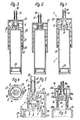
Es sind dargestellt in
- Fig. 1 ein erfindungsgemäßer Wirkstoff-Spender im Axialschnitt,
- Fig. 2 und
- Fig. 3 der Wirkstoff-Spender in Darstellungen gemäß Fig. 1, jedoch in anderen Funktionsstellungen,
- Fig. 4 ein Schnitt nach der Linie IV/IV in Fig. 3,
- Fig. 5 ein Ausschnitt der Fig. 1 in vergrößerter Darstellung,
- Fig. 6 eine weitere Ausführungsform in einer Darstellung entsprechend Fig. 5,
- Fig. 7 eine weitere Ausführungsform eines Spenders, teilweise im Axialschnitt,
- Fig. 8 ein Ausschnitt der Fig. 7 in vergrößerter Darstellung und am Ende des Pumphubes.
- 1 shows an active substance dispenser according to the invention in axial section,
- Fig. 2 and
- 3 the agent dispenser in representations according to FIG. 1, but in other functional positions,
- 4 shows a section along the line IV / IV in FIG. 3,
- 5 shows a detail of FIG. 1 in an enlarged view,
- 6 shows a further embodiment in a representation corresponding to FIG. 5,
- 7 shows a further embodiment of a dispenser, partly in axial section,
- Fig. 8 shows a detail of Fig. 7 in an enlarged view and at the end of the pump stroke.
Wie die Figuren 1 bis 5 zeigen, weist ein erfindungsgemäßer Wirkstoff-Spender einen beispielsweise als Standgefäß ausgebildeten Vorratsbehälter 2 und eine an diesem gleichzeitig als Verschlußkappe angeordnete Schubkolben-Pumpe 1 auf, die beispielsweise an dem der Standfläche des Vorratsbehälters 2 gegenüberliegenden oberen Ende vorgesehen ist.As shown in FIGS. 1 to 5, an active substance dispenser according to the invention has a
Die Schubkolben-Pumpe 1, von der wesentliche Teile bzw. die gegenüber dem Vorratsbehälter 2 lagefesten Teile einstückig mit diesem ausgebildet sind, weist einen in Längsrichtung des Vorratsbehälters 2 gegenüber diesem über mehr als den Pumphub bewegbaren Zylinder 3 auf, welchem ein am Vorratsbehälter 2 lagefest angeordneter Pumpkolben 4 zugeordnet ist. Der Zylinder 3 ist seinerseits an seinem freien Ende als Vorsaugkolben 5 ausgebildet, der in einem den Pumpkolben 4 mit Abstand umgebenden Zwischenzylinder 6 geführt ist. Dieser Zwischenzylinder 6 bildet den am zugehörigen Ende vorgesehenen Hals des Vorratsbehälters 2, wobei sowohl die Innenquerschnitte des Zwischenzylinders 6 wie auch die des Zylinders 3 gegenüber denen des Vorratsbehälters 2 kleiner sind. Der Zwischenzylinder 6 reicht bis zur zugehörigen Stirnwand 7 des beispielsweise durchgehend zylindrischen'Vorratsbehälters 2 und steht mit seinem freien Ende weiter vor als der in ihm liegende Pumpkolben 4, der somit vollständig innerhalb des Zwischenzylinders 6 vorgesehen ist. Der Pumpkolben 4 ist auf einem - in seiner Achsrichtung gesehen - kreuzförmigen Kolbenschaft 8 angeordnet, wodurch vier Obertrittsöffnungen 9 zwischen dem Innern des Vorratsbehälters 2 und dem Zylinderraum 10 des Zwischenzylinders 6 gebildet sind, die etwa in der Ebene der Stirnwand 7 liegen.The push piston pump 1, of which essential parts or the parts which are fixed in position relative to the
Der Vorsaugkolben 5 ist soweit annähernd bis zum freien Ende des Zwischenzylinders 6 verfahrbar, daß der Pumpkolben 4 etwa auf dem letzten Drittel des Rückhubes vollständig aus dem offenen Ende des Zylinders 3 herausgefahren ist, derart, daß dessen dem Pumpkolben 4 zugekehrte stirnseitige öffnung eine zum Zylinderraum 10 offene und durch den Pumpkolben 4 nach Art einer Schlitzsteuerung verschließbare Verbindungsöffnung 11 bildet. Diese Verbindungsöffnung 11 ist im wesentlichen durch das engere Ende einer trichter- bzw. kegelstumpfförmig erweiterten Einlauffläche 12 für den Pumpkolben 4 begrenzt, die mit ihrem engeren Ende unmittelbar an die Kolbenlaufbahn 13 des Zylinders 3 anschließt und deren weiteres Ende größer als der Kolbenquerschnitt ist; im dargestellten Ausführungsbeispiel weist die Einlauffläche 12 einen Verjüngungswinkel von etwa 90° auf.The priming piston 5 can be moved approximately to the free end of the
Die beispielsweise zylindrische Kolbenlaufbahn 13 begrenzt denjenigen Teil des Pumpraumes der Schubkolben-Pumpe 1, welcher als Dosierraum 15 vorgesehen ist, da der Pumpkolben 4 am Ende des Pumphubes wenigstens annähernd an der ringschulterförmigen stirnseitigen Endfläche 14 der Kolbenlauffläche 13 anliegt.The, for example, cylindrical piston race 13 limits that part of the pump chamber of the push piston pump 1 which is provided as a
Der Zylinder 3 ist baulich bzw. einstückig mit einem Auslaßnippel 16 vereinigt, welcher unter Zwischenschaltung eines als Rückschlagventil ausgebildeten Auslaßventiles 17 den Dosierraum 15 mit einer Auslaßöffnung 18 für den Wirkstoff verbindet. Diese Leitungsverbindung 19 ist verhältnismäßig kurz und im wesentlichen geradlinig, wobei sie im Querschnitt zum Rückschlagventil 17 abgestuft abnimmt und zwischen dem Rückschlagventil 17 undder Auslaßöffnung 18 wieder erweitert ist. Im dargestellten Ausführungsbeispiel ist die Leitungsverbindung 19 durch einen ersten, zum Dosierraum 15 achsgleichen Abschnitt mit gegenüber dem Dosierraum 15 reduziertem Querschnitt, einen an diesen anschließenden, im Querschnitt nochmals reduzierten und ebenfalls in der Achse des Dosierraumes 15 liegenden längeren Abschnitt und zwei oder mehr radial in diesen mündende Austrittsöffnungen im Auslaßnippel 16 gebildet, wobei diese Austrittsöffnungen 20 gleichzeitig die Ventilöffnungen des Auslaßventiles 17 bilden. Als Ventilschließteil 21 weist das Auslaßventil 17 einen elastischen, den Auslaßnippel 16 auf seiner ganzen Länge umgebenden und gegen axiales Verschieben gesicherten Ventilstrumpf auf, welcher den Auslaßnippel 16 im Bereich der an dessen Umfang liegenden Austrittsöffnungen 20 elastisch eng umgibt und über das Ende des Auslaßnippels 16 derart vorsteht, daß er mit seinem Ende unmittelbar die Auslaßöffnung 18 bildet, deren öffnungsquerschnitt somit im wesentlichen gleich dem größten Querschnitt des Auslaßnippels 16 ist.The cylinder 3 is structurally or integrally united with an
Der Zylinder 3 und der Auslaßnippel 16 sind an der zur Mittelachse des Spenders rechtwinkligen Stirnwand 23 einer Handhabe 27 vorgesehen und einstückig mit dieser ausgebildet. Diese Handhabe 22 weist mehrere, im dargestellten Ausführungsbeispiel vierjgleichmäßig über den Umfang verteilte, zum Spender 8 parallele Führungsarme 24 auf, welche den Vorratsbehälter 2 am Umfang mit geringem Abstand umgeben und an ihren Enden mit nach innen gerichteten Nocken 25 versehen sind, denen als den Rückhub begrenzender Anschlag 26 ein über den Außenumfang des Vorratsbehälters 2 vorstehender Ringbund zugeordnet ist. Innerhalb der Führungsarme 24 ist als Rückstellfeder 27 eine Schraubendruckfeder vorgesehen, die einerseits an der Innenseite der Stirnwand 23 und andererseits am Anschlag 26 abgestützt ist und über einen Teil ihrer Länge den Vorratsbehälter 2 am Umfang umgibt. Stattdessen ist auch denkbar, die von der Stirnwand 23 abgekehrten Enden der Führungsarme 24, beispielsweise durch einstückige Herstellung, an dem Vorratsbehälter 2 zu befestigen und hinsichtlich ihrer Elastizität und Festigkeit so auszubilden, daß sie selbst als Rückstollfedern derart wirken, daß sie beim Pumphub aus ihrer gestreckten Lage federnd bogenförmig nach außen gewölbt werden.The cylinder 3 and the
Den Obertrittsöffnungen 9 gegenüberliegend ist der Schleppkolben 29 entlang seiner Zylinderlaufbahn mit verhältnismäßig geringer Reibung frei beweglich geführt, wobei der Vorratsbehälter 2 an der vom Vorratsraum 28 abgekehrten Seite des Kolbens 29 offen bzw. mit einer Druckausgleichsöffnung versehen ist, so daß an dieser Seite des Kolbens 29 kein Unterdruck entstehen kann.Opposite the
In Ausgangsstellung gemäß Fig. 1 ist der Vorratsraum 28 einschließlich des Zylinderraumes 10, des Dosierraumes 15 und der Leitungsverbindung 19 vollständig mit dem dosiert auszubringenden Wirkstoff gefüllt und der Zylinder 3 steht unter der Kraft der Rückstellfeder 27 am Ende seines Rückhubes. Wird nun der Zylinder 3 entgegen der Kraft der Rückstellfeder 27 in Richtung zum Pumpkolben 4 bewegt, so wird zunächst ein Teil der im Zylinderraum 10 befindlichen Wirkstoffmenge in Richtung zum Vorratsraum 28 verdrängt, bis der Pumpkolben 4 entlang der Einlauffläche 12 den Anfang der Kolbenlaufbahn 13 des Dosierraumes 15 erreicht und diesen dadurch verschlossen hat; die Schließspannung des Auslaßventiles 17 ist so groß gewählt, daß es bis zu diesem Augenblick noch nicht öffnet. Daher wird in dieser Phase der Kletterkolben zurückgedrückt und, falls er relativ festsitzen sollte, gelockert. Im weiteren Verlauf des Pumphubes wird durch den Pumpkolben 4 die im Dosierraum 15 befindlichen Wirkstoffmenge unter Druck gesetzt, wodurch das Auslaßventil 17 gemäß Fig. 2 öffnet, so daß die dosierte Wirkstoffmenge über die Leitungsverbindung 19 an der Auslaßöffnung 18 austritt. Der Gesamthub beträgt dabei beispielsweise nur 5 mm und der Vorratsbehälter 2 des in den Fig. 1 bis 5 vergrößert dargestellten Spenders faßt beispielsweise nur etwa vier Kubikzentimeter.In the starting position according to FIG. 1, the
Am Ende des Pumphubes gemäß Fig. 2 schließt das Auslaßventil 17 von selbst wieder durch die elastische Spannung des Ventilschließteiles 21. Wird nunmehr die Handhabe 22 freigegeben, so wird der Zylinder 3 gemäß Fig. 3 unter der Kraft der Rückstellfeder 27 zu seiner Ausgangsstellung hin zurückbewegt. Hierbei bewegt sich der Vorsaugkolben 5 im Zwischenzylinder 6 zurück, ebenso wie dies für den Pumpkolben 4 und den Zylinder 3 der Fall ist. Durch den dabei im Zwischenzylinder 6 auftretenden Unterdruck wird Wirkstoff aus dem Vorratsraum 28 in den Zwischenzylinder 6 nachgesaugt. Sobald der Pumpkolben 4 bei diesem Rückhub an den Beginn der Einlauffläche 12 gelangt ist, wird bei der weiteren Rückhubbewegung die Verbindungsöffnung 11 schlagartig freigegeben, wobei in diesem Augenblick durch die Rückhubbewegung des Pumpkolbens 4 im Dosierraum 15 das Maximum des möglichen Unterdruckes erreicht ist. Sobald die Verbindungsöffnung 11 freigegeben ist, wird daher der in den Zwischenzylinder 6 angesaugte Wirkstoff schlagartig und unter vollständiger Füllung in den Dosierraum 15 angesaugt. Der Zylinderraum 10 gehört somit zum Vorratsraum 28, in welchen die Verbindungsöffnung 11 während des Rückhubes vollständig eingetaucht ist. Während des Rückhubes und des dadurch bewirkten Ansaugens des Wirkstoffes wird der Kletterkolben 29 durch den im Vorratsraum 28 entstehenden Unterdruck um eine der Dosiermenge entsprechende Strecke nachgezogen, derart, daß der Vorratsraum 28 zwar im Volumen abnimmt, aber stets vollständig gefüllt bleibt.At the end of the pumping stroke according to FIG. 2, the
In Fig. 6 sind für einander entsprechende Teile die gleichen Bezugszeichen wie in den Fig. 1 bis 5, jedoch mit dem Index "a" verwendet. Die Schubkolben-Pumpe 1a gemäß Figur 6 ist derart vom Vorratsbehälter 2a abnehmbar ausgebildet, daß dieser durch seinen Behälterhals 31 mit Wirkstoff nachgefüllt werden kann. Zu diesem Zweck sind der Pumpkolben 4a und derZwischenzylinder 6a baulich mit einer Schraubhülse 7a vereinigt, welche auf ein Außengewinde des Behälterhalses 31 lösbar und unter Bildung eines vakuumdichten Verschlusses aufgeschraubt werden kann. Die Handhabe 22a ist in diesem Fall hinsichtlich Ihres Rückhubes unmittelbar gegenüber der Schraubhülse 7a anschlagbegrenzt.In Fig. 6, the same reference numerals as in Figs. 1 to 5, but with the index "a" are used for corresponding parts. The push piston pump 1a according to FIG. 6 is designed to be removable from the storage container 2a in such a way that it can be refilled with active substance through its
Der Auslaßnippel ist bei der Ausführungsform nach Fig. 6 durch eine Auslaßmuffe 16a gebildet, die mit einem Außengewinde versehen ist, mit welchem sie in einem in der Zylinderwandung 13a des Pumpenzylinders 3a vorgesehenen Stellgewinde 30 in Richtung des Pumphubes verstellbar und durch Selbsthemmung feststellbar geführt ist. Diese Auslaßmuffe 16a bildet mit ihrem inneren Ende die dem Pumpkolben 4a gegenüberliegende Stirnwand 14a des Dosierraumes 15a, so daß durch Verstellen der Auslaßmuffe 16a die Größe des Dosierraumes 15a und damit die dosiert auszubringende Wirkstoffmenge verändert werden kann.The outlet nipple in the embodiment according to FIG. 6 is formed by an outlet sleeve 16a which is provided with an external thread with which it is adjustable in the direction of the pump stroke in an adjusting thread 30 provided in the
Der erfindungsgemäße Wirkstoff-Spender ist beispielsweise zum dosierten Ausbringen von Wirkstoffen für Inhalationsgeräte oder als Tropfspender, der auf eine genaue Anzahl von je Pumphub auszubringenden Flüssigkeitstropfen ausgelegt sein kann, besonders geeignet. Er kann aber auch für andere Medien als Arzneimittel verwendet werden.The active ingredient dispenser according to the invention is particularly suitable, for example, for the metered delivery of active ingredients for inhalation devices or as a drip dispenser, which can be designed for an exact number of liquid drops to be dispensed per pump stroke. However, it can also be used for other media than drugs.
In den Fig. 7 und 8 sind für einander entsprechende Teile die gleichen Bezugszeichen wie in den vorangehenden Figuren, jedoch mit den Index "b" verwendet.7 and 8, the same reference numerals as in the previous figures, but with the index "b" are used for corresponding parts.
Der Wirkstoff-Spender gemäß den Fig. 7 und 8 weist als Pumpe eine von Hand zu betätigende Kolbenpumpe 1b auf, die unter Zwischenlage einer Dichtung 32 mit einem hülsenförmigen Gehäuseteil 33 an der Stirnfläche des Halses 31b des Behälters 2b durch einen Spannring befestigt ist und mit allen Teilen achsgleich zum Behälter 2b liegt. An dem nach Art zweier koaxial ineinanderliegender und an der äußeren Stirnseite ineinander übergehender Hülsen ausgebildeten Gehäuseteil 33 ist der Zylinder 3b mit seinem äußeren, formschlüssig zwischen die beiden Hülsen des Gehäuseteiles 33 eingreifenden Endabschnitt so befestigt, daß er den Innenumfang des Halses 31b mit geringem Spaltabstand umgibt und mit einem, sein inneres verjüngtes Ende bildenden Saugstutzen 34 verhältnismäßig tief in den Vorratsraum 28b ragt. Der Zylinder 3b bildet etwa im Bereich des Halses 31b eine Kolbenlaufbahn 13b für den Kolben 4b, der durch einen inneren Endabschnitt eines hülsenförmigen Bauteiles aus gummielastischem Werkstoff gebildet ist. Der in Richtung des Pumphubes spitzwinklig kegelstumpfförmig erweiterte und in seiner Wandungsdicke gleichmäßig verjüngte Kolben 4b geht an seinem hinteren Ende einstückig in ein ringförmiges Schließteil 21b eines Auslaßventiles 17b über, das seinerseits an der vom Kolben 4b abgekehrten Seite in eine durch Axialdruck federnd verkürzbare Stauchhülse 35 übergeht. An dem vom Kolben 4b abgekehrten Ende bildet die Stauchhülse 35 einen einstückig mit dem Kolben 4b ausgebildeten Flanschring 36, welcher in einer Stirnnut des Kolbenschaftes 8b befestigt ist. Die Stauchhülse 35 ist im Querschnitt an der Außenseite konvex gewölbt, wobei diese Wölbung bei Stauchung bzw. Verkürzung der Stauchhülse 35 zunimmt. Der hülsenförmige elastische Bauteil ist zwischen der am freien Ende des Kolbens 4b vorgesehenen, unmittelbar durch den Kolben gebildeten und an der Kolbenlaufbahn 13b dicht anliegenden, ringlippenartigen Kolbendichtung 37 und der Befestigung des Flanschringes 36 im Kolbenschaft 8b dicht geschlossen.The active substance dispenser according to FIGS. 7 and 8 has as a pump a manually operated piston pump 1b, which is fastened with a
Der Kolbenschaft 8b, der in seinem Inneren den zugehörigen Abschnitt der Leitungsverbindung 19b zwischen Zylinderraum 10b und Austragöffnung 18b bildet, besteht aus zwei Teilen, nämlich einem äußeren hülsenförmigen Teil 38 und einem Stempel 39, der über einen Teil der Länge des hülsenförmigen Teiles 38 in dessen Inneres bzw. dem Behälter 2b zugekehrtes Ende unter Freilassung der Leitungsverbindung eingreift. Am inneren Ende des hülsenförmigen Teiles 38 ist die Stirnnut für die Aufnahme des Flanschringes 36 vorgesehen. Der Stempel 39 weist im Bereich des Schließteiles 21b einen über seinen Umfang vorstehenden Ringbund auf, dessen zum Saugstutzen 34 stumpfwinklig kegelstumpfförmig erweiterte, vom Saugstutzen 34 abgekehrte Stirnfläche eine der beiden Schließflächen, nämlich die Schließfläche 40 des Auslaßventiles 17b bildet. Der Schließteil 21b bildet an seinem Innenumfang die andere, an die Schließfläche 40 angepasste Ventil-Schließfläche 41, welche bei Ausgangslage der Pumpe mit verhältnismäßig großem Schließdruck unter der Kraft der als Ventilschließfeder dienenden Stauchhülse 35 an der Schließfläche 40 anliegt.The piston shaft 8b, which forms the associated section of the
Die Innenhülse 6b des Gehäuseteiles 33, welche in das hintere offene Ende des Zylinders 3b eingreift, bildet mit ihrem freien, im Zylinder 3b liegenden Ende eine Gegenschulter 26b für eine am Außenumfang des Schließteiles 21b vorgesehene ringschulterförmige Anschlagfläche 22, die im Querschnitt spitzwinklig kegelstumpfförmig zum Saugstutzen 34 hin erweitert ist. Am Ende der Rückstellbewegung des Kolbens 4b läuft die Anschlagfläche 42 auf die Gegenschulter 26b auf, wodurch die Stauchhülse 35 geringfügig gestreckt und der Schließteil 21b des Auslaßventiles 17b zwangsläufig sowohl axial gegen die Schließfläche 40 gepresst als auch radial zur Achse des Auslaßventiles 17b vorgespannt wird, so daß ein äußerst dichter und sicherer Schluß des Auslaßventiles 17b gewährleistet ist. Der Zylinder 3b ist mit dem Gehäuseteil 33 druckdicht baulich vereint, so daß bei Ausgangsstellung des Kolbens 4b an dessen Außenseite ein Ringraum 43 vorgesehen ist, welcher zwischen der Kolbendichtung 37 und derjenigen, ventilartigen Abdichtung liegt, welche durch Anlage der Gegenschulter 26b an der Anschlagfläche 42 gebildet ist.The
Am inneren Ende geht die Kolbenlaufbahn 13b in eine ringförmig nach innen vorspringende Anschlagschulter 14b über, auf welche der Kolben 4b am Ende des Pumphubes gemäß Fig. 8 mit seiner freien Stirnfläche aufläuft. Ober diese Stellung, bei welcher der Kolben 4b die Anschlagschulter 14b erreicht hat, kann der Kolbenschaft 8b in Richtung des Pumphubes um ein geringes Wegstück hinaus bewegt werden, so daß dann die Schließfläche 40 von der Ventil-Schließfläche 41 abhebt und zwischen diesen Flächen eine ringförmige Durchtrittsöffnung 20b des Auslaßventiles 17b freigegeben wird. Hierbei wird die Stauchhülse 35 elastisch federnd gestaucht und dadurch verkürzt. Im Augenblick des Freigebens der Durchtrittsöffnung 20b kann der durch den vorangehenden Pumphub bereits unter Druck gesetzte Wirkstoff schlagartig in die Leitungsverbindung 19b und von dort durch die Austragöffnung 18b nach außen gelangen. Sobald der Kolbenschaft 8b wieder freigegeben wird, wird er durch die in seiner Achse liegende und unmittelbar an ihm angreifende Rückstellfeder 27b zurückbewegt, wobei zuerst das Auslaßventil 17b unter der rückstellenden Federkraft der Stauchhülse 35 schließt und danach der Kolben 4b in seine Ausgangslage zurückgeführt wird. Während des Rückhubes des Kolbens 4b wird über den Saugstutzen 34 und unter öffnung eines an diesen anschließenden, als Kugelventil ausgebildeten Rückschlagventiles 44 Wirkstoff in den Zylinderraum 10b nachgesaugt und dadurch zum Austrag während des nächsten Pumphubes bereitgestellt.At the inner end, the
Auf das äußere Ende des hülsenförmigen Teiles 38 des Kolbenschaftes 8b ist mit einer Steckverbindung ein hülsenförmiger Anschlußnippel 16b aufgesetzt, der einen einstückigen Bauteil mit einer ihn umgebenden, kappenartigen Handhabe 22b bildet und mit einer Außenhülse an deren Stirnwand 23b angeordnet ist. Am freien Ende des Anschlußnippels 16b, der zur Verringerung seiner Innenquerschnitte und damit der Durchlaßquerschnitte für den Wirkstoff mit einem Einsatz versehen sein kann, ist die als Zerstäuberöffnung ausgebildete Austragöffnung 18b vorgesehen.On the outer end of the sleeve-shaped part 38 of the piston shaft 8b, a sleeve-shaped connecting
Der Schleppkolben 29b weist einen äußeren Kolbenring mit zwei an beiden Enden vorgesehenen, ringförmigen, dichten Lippen und eine in diesem liegende Passhülse 45 auf, die mit ihrer offenen, der Kolbenpumpe 1b zugekehrten Stirnseite einteilig und dicht in den Kolbenring 29b übergeht. Die Innenquerschnitte der achsgleich zu dem über die Stirnwand 7b des Behälters 2b in den Vorratsraum 28b ragenden Abschnittes der Kolbenpumpe 1b liegenden Passhülse 45, die an ihrem von der Kolbenpumpe 1b abgekehrten, über das zugehörige Ende des Kolbenringes vorstehenden Ende napfförmig geschlossen ist, sind so an die Außenform des genannten vorstehenden Abschnittes der Kolbenpumpe 1b angepasst, daß bei der dem geleerten Vorratsraum 28b zugehörigen Endstellung des Schleppkolbens 29b der vorstehende Abschnitt der Kolbenpumpe 1b das Innere der Passhülse 45 nahezu vollständig lückenfrei ausfüllt und das freie Ende des Saugstutzens 34 an der Bodenwand der Passhülse 45 anliegt. In dieser Stellung liegt auch die zugehörige Stirnfläche des Schleppkolbens 29b nahezu ganzflächig an der Innenseite der Stirnwand 7b des Behälters 2b an. Der Vorratsraum 28b kann dadurch bis auf winzigste Reste von Wirkstoff vollständig entleert werden.The trailing
Bei der Ausführungsform nach den Fig. 7 und 8 ist des weiteren besonders vorteilhaft, daß das zu zerstäubende Produkt, also der Wirkstoff, vor dem Austrag nicht mit Sauerstoff in Verbindung kommt, da zu keinem Zeitpunkt der Ausbringung ein Verbindungskanal zwischen Behältnis und Außenluft entsteht. Die Zerstäubung bzw. der Austrag kann auch in jeder Lage des Spenders, zum Beispiel in Kopflage erfolgen, da Wirkstoff stets am Saugstutzen 34 vorhanden ist.In the embodiment according to FIGS. 7 and 8, it is furthermore particularly advantageous that the product to be atomized, that is to say the active substance, does not come into contact with oxygen before the discharge, since at no point in time during the application is there a connecting channel between the container and the outside air. The atomization or discharge can also take place in any position of the dispenser, for example in an upside-down position, since active substance is always present on the
Die aus der Beschreibung und Zeichnunn sowie den Ansprüchen hervorgehenden einzelnen Merkmale können jeweils für sich allein oder zu mehreren z.B. in Form von Unterkombinationen vorteilhafte und für sich schutzfähiae Ausführungen darstellen, für die hier Schutz beansprucht wird.The individual features resulting from the description and drawing as well as from the claims can each be used individually or in groups of e.g. in the form of sub-combinations represent advantageous and protectable versions for which protection is claimed here.
Claims (14)
Priority Applications (1)
| Application Number | Priority Date | Filing Date | Title |
|---|---|---|---|
| DE8686105985T DE3480057D1 (en) | 1983-10-28 | 1984-08-15 | Fluid dispenser |
Applications Claiming Priority (2)
| Application Number | Priority Date | Filing Date | Title |
|---|---|---|---|
| DE3339180A DE3339180C2 (en) | 1983-10-28 | 1983-10-28 | Discharge device for media |
| DE3339180 | 1983-10-28 |
Related Child Applications (1)
| Application Number | Title | Priority Date | Filing Date |
|---|---|---|---|
| EP86105985.5 Division-Into | 1986-04-30 |
Publications (3)
| Publication Number | Publication Date |
|---|---|
| EP0143183A2 true EP0143183A2 (en) | 1985-06-05 |
| EP0143183A3 EP0143183A3 (en) | 1986-08-27 |
| EP0143183B1 EP0143183B1 (en) | 1988-06-08 |
Family
ID=6212988
Family Applications (2)
| Application Number | Title | Priority Date | Filing Date |
|---|---|---|---|
| EP86105985A Expired EP0201809B1 (en) | 1983-10-28 | 1984-08-15 | Fluid dispenser |
| EP84109706A Expired EP0143183B1 (en) | 1983-10-28 | 1984-08-15 | Dispenser for active materials |
Family Applications Before (1)
| Application Number | Title | Priority Date | Filing Date |
|---|---|---|---|
| EP86105985A Expired EP0201809B1 (en) | 1983-10-28 | 1984-08-15 | Fluid dispenser |
Country Status (4)
| Country | Link |
|---|---|
| US (2) | US4694977A (en) |
| EP (2) | EP0201809B1 (en) |
| JP (1) | JPH0672788B2 (en) |
| DE (3) | DE3339180C2 (en) |
Cited By (2)
| Publication number | Priority date | Publication date | Assignee | Title |
|---|---|---|---|---|
| EP0662352A1 (en) * | 1994-01-07 | 1995-07-12 | S O F A B Société Anonyme | Device for storing and distributing a liquid product |
| FR2718109A1 (en) * | 1994-03-30 | 1995-10-06 | Reboul Smt | Refillable packaging and its cartridge. |
Families Citing this family (70)
| Publication number | Priority date | Publication date | Assignee | Title |
|---|---|---|---|---|
| DE3530486A1 (en) * | 1985-08-27 | 1987-03-05 | Pfeiffer Erich Gmbh & Co Kg | DISCHARGE DEVICE FOR FLOWABLE MEDIA |
| FR2593142B1 (en) * | 1986-01-17 | 1988-12-30 | Oreal | DISPENSING DEVICE. |
| JPH0520982Y2 (en) * | 1986-07-07 | 1993-05-31 | ||
| GB2196116B (en) * | 1986-10-07 | 1990-08-15 | Weston Terence E | Apparatus for chemical analysis. |
| US4809878A (en) * | 1987-01-28 | 1989-03-07 | Chesebrough-Pond's Inc. | Pump dispenser for viscous fluids |
| US4854484A (en) * | 1987-01-28 | 1989-08-08 | Chesebrough-Pond's Inc. | Viscous product dispenser |
| EP0373237A1 (en) * | 1988-12-13 | 1990-06-20 | Siemens Aktiengesellschaft | Pocket inhaler device |
| DE3914995A1 (en) * | 1989-05-08 | 1991-01-17 | Peter Gartner | SPRAY CAN / BOTTLE WITH INTEGRATED PUMPING DEVICE |
| JPH0317930U (en) * | 1989-07-05 | 1991-02-21 | ||
| FR2668119B2 (en) * | 1990-10-18 | 1992-12-31 | Valois | PROCESS FOR VACUUM PACKAGING IN RIGID ENCLOSED DISPENSERS AND CORRESPONDING DISPENSERS. |
| CA2027786C (en) * | 1989-10-31 | 1997-01-28 | Koichi Sugita | Combination container and pump |
| EP0446513B1 (en) * | 1990-03-16 | 1994-11-02 | Kabushiki Kaisha Top | Pump assembly |
| SG45171A1 (en) * | 1990-03-21 | 1998-01-16 | Boehringer Ingelheim Int | Atomising devices and methods |
| EP0472915B2 (en) * | 1990-08-31 | 2002-03-20 | Ing. Erich Pfeiffer GmbH | Dispenser for fluid |
| IL100224A (en) * | 1990-12-04 | 1994-10-21 | Dmw Tech Ltd | Atomising nozzles |
| EP0560858B1 (en) * | 1990-12-04 | 1996-02-14 | Dmw (Technology) Limited | Nozzle assembly for preventing back-flow |
| DE4110303A1 (en) * | 1991-03-28 | 1992-10-01 | Pfeiffer Erich Gmbh & Co Kg | DISCHARGE DEVICE FOR MEDIA |
| EP0531257A1 (en) * | 1991-09-05 | 1993-03-10 | Ciba-Geigy Ag | Method and device for storing and administering peptid containing dispersions |
| ES2133378T3 (en) * | 1991-12-02 | 1999-09-16 | Py Daniel C | APPARATUS FOR APPLYING A MEDICATION TO THE EYE. |
| US5267986A (en) | 1992-04-06 | 1993-12-07 | Self-Instill & Co., Inc. | Cartridge for applying medicament to an eye from a dispenser |
| EP0686597A1 (en) * | 1994-06-09 | 1995-12-13 | Wilhelm A. Keller | An apparatus with a container and pump for vacuum unloading of contents |
| US5435461A (en) * | 1994-08-03 | 1995-07-25 | Hewlett-Packard Company | Cartridge for dispensing toner concentrate |
| FR2725247B1 (en) * | 1994-10-03 | 1996-12-20 | Py Daniel C | FLUID PUMP WITHOUT DEAD VOLUME |
| AU690438B2 (en) * | 1995-03-14 | 1998-04-23 | Siemens Aktiengesellschaft | Ultrasonic atomizer device with removable precision dosating unit |
| DE69621604T2 (en) * | 1995-03-14 | 2002-11-28 | Siemens Ag | ULTRASONIC SPRAYER WITH REMOVABLE PRECISION DOSING UNIT |
| FR2731992B1 (en) * | 1995-03-21 | 1997-04-30 | Oreal | DISPENSER OF LIQUID OR PASTY PRODUCT FOR USE IN PARTICULAR IN COSMETICS |
| DE19536902A1 (en) * | 1995-10-04 | 1997-04-10 | Boehringer Ingelheim Int | Miniature fluid pressure generating device |
| US5749500A (en) * | 1996-04-23 | 1998-05-12 | Kraus; Joey | Liquid retrieving adaptor for cylindrical containers |
| AUPO012196A0 (en) * | 1996-05-28 | 1996-06-20 | N.J. Phillips Pty. Limited | An applicator |
| AU710557B2 (en) * | 1996-05-28 | 1999-09-23 | N.J. Phillips Pty. Limited | An applicator |
| CH692112A5 (en) * | 1997-08-21 | 2002-02-15 | Pack Part Gmbh | Device for dispensing a highly viscous portioned filling material. |
| US5855322A (en) * | 1997-09-10 | 1999-01-05 | Py; Daniel | System and method for one-way spray aerosol tip |
| DE19739990A1 (en) | 1997-09-11 | 1999-03-18 | Pfeiffer Erich Gmbh & Co Kg | Media Donor |
| DE19739989A1 (en) | 1997-09-11 | 1999-03-18 | Pfeiffer Erich Gmbh & Co Kg | Media Donor |
| DE19741957A1 (en) * | 1997-09-23 | 1999-03-25 | Wischerath Josef Gmbh Co Kg | Container with closure, filled with pharmaceutical paste or fluid |
| US6033384A (en) | 1997-12-18 | 2000-03-07 | Py; Daniel | One-way actuation release mechanism for a system for applying medicament |
| DE29811242U1 (en) * | 1998-06-24 | 1999-11-04 | Fritz Albert Riegler GmbH & Co. KG, 64367 Mühltal | Application device for aseptic fluids |
| EP1020233A1 (en) * | 1999-01-13 | 2000-07-19 | The Procter & Gamble Company | Dosing and delivering system |
| US6302101B1 (en) | 1999-12-14 | 2001-10-16 | Daniel Py | System and method for application of medicament into the nasal passage |
| ATE348664T1 (en) | 2001-09-21 | 2007-01-15 | Pfeiffer Erich Gmbh & Co Kg | DOSING DEVICE WITH A MEDIA STORAGE AND PUMPING DEVICE THEREFOR |
| WO2003026804A1 (en) | 2001-09-21 | 2003-04-03 | Ing. Erich Pfeiffer Gmbh | Dosing device with a medium reservoir and a pump device |
| US7645300B2 (en) | 2004-02-02 | 2010-01-12 | Visiogen, Inc. | Injector for intraocular lens system |
| USD537344S1 (en) | 2005-07-08 | 2007-02-27 | S.C. Johnson & Son, Inc. | Applicator |
| USD539147S1 (en) | 2005-07-08 | 2007-03-27 | S.C. Johnson & Son, Inc. | Applicator refill |
| US7520406B2 (en) * | 2005-07-08 | 2009-04-21 | S. C. Johnson & Son, Inc. | Device for dispensing a controlled dose of a flowable material |
| USD592513S1 (en) | 2006-02-28 | 2009-05-19 | S.C. Johnson & Son, Inc. | Applicator |
| USD587584S1 (en) | 2006-02-28 | 2009-03-03 | S.C. Johnson & Son, Inc. | Applicator refill |
| US7434602B2 (en) * | 2006-08-03 | 2008-10-14 | University Of Medicine & Dentistry Of New Jersey | Drip chamber dropper bottle |
| CA120556S (en) | 2006-11-29 | 2008-01-07 | Johnson & Son Inc S C | Applicator for toilet cleaner |
| USD603274S1 (en) * | 2007-01-31 | 2009-11-03 | Sabritas, S. De R.L. De C.V. | Food container |
| US20080210228A1 (en) * | 2007-03-02 | 2008-09-04 | Corbco, Inc. | Monodose nasal sprayer |
| US8210167B2 (en) * | 2007-03-02 | 2012-07-03 | Corbco, Inc. | Manually operated monodose nasal sprayer |
| TW201515714A (en) * | 2007-05-30 | 2015-05-01 | Glaxo Group Ltd | Fluid dispenser |
| USD588925S1 (en) | 2008-04-02 | 2009-03-24 | Mary Kay Inc. | Container |
| USD588916S1 (en) | 2008-04-02 | 2009-03-24 | Mary Kay Inc. | Container |
| IT1393959B1 (en) | 2009-04-30 | 2012-05-17 | Lumson Spa | DISPENSING DEVICE FOR FLUID SUBSTANCES SEALED IN A GUIDED DEFORMATION BAG |
| IT1395126B1 (en) | 2009-07-30 | 2012-09-05 | Lumson Spa | "CONTAINER IMPROVED ASSOCIATED WITH PUMPS AIRLESS AND METHOD FOR ITS REALIZATION" |
| IT1395730B1 (en) | 2009-07-31 | 2012-10-19 | Lumson Spa | "CONTAINER ASSOCIATED WITH PUMPS AIRLESS AND METHOD FOR ITS REALIZATION" |
| WO2011026198A1 (en) * | 2009-09-07 | 2011-03-10 | Mk International Pty Ltd | Nasal spray pump |
| US8408427B2 (en) * | 2009-09-07 | 2013-04-02 | Mk International Pty Ltd | Single dose nasal spray pump |
| DE102009040783B4 (en) * | 2009-09-09 | 2012-04-26 | F. Holzer Gmbh | Metering device for metered dispensing of liquid preparations, method for filling and use of a metering device according to the invention |
| US8950394B2 (en) | 2010-01-12 | 2015-02-10 | Dance Biopharm Inc. | Preservative-free single dose inhaler systems |
| US20130269684A1 (en) | 2012-04-16 | 2013-10-17 | Dance Pharmaceuticals, Inc. | Methods and systems for supplying aerosolization devices with liquid medicaments |
| IT1397891B1 (en) * | 2010-01-15 | 2013-02-04 | Lumson Spa | DECORATED CONTAINER ASSOCIATED WITH PUMPS AIRLESS AND METHOD FOR ITS REALIZATION. |
| IT1398945B1 (en) | 2010-03-17 | 2013-03-28 | Lumson Spa | METHOD FOR THE REALIZATION OF A CONTAINER TO BE USED WITH A HERMETIC PUMP. |
| FR2978431B1 (en) * | 2011-07-25 | 2013-08-23 | Valois Sas | FLUID PRODUCT DISPENSER |
| BE1021623B1 (en) * | 2013-12-20 | 2015-12-21 | Reload Labs | RECHARGEABLE SPRAYER |
| DE202018002072U1 (en) * | 2018-04-24 | 2019-07-25 | Schwan-Stabilo Cosmetics Gmbh & Co. Kg | Device for applying a viscous substance |
| WO2020058884A1 (en) | 2018-09-19 | 2020-03-26 | Prc-Desoto International, Inc. | Expandable plunger head assemblies for sealant dispensing guns |
| EP4492017A1 (en) * | 2023-07-13 | 2025-01-15 | Brill Engines, S.L. | A method and a system for dispensing a dose of a liquid or pasty product occupying a storage enclosure of variable volume in a container |
Family Cites Families (37)
| Publication number | Priority date | Publication date | Assignee | Title |
|---|---|---|---|---|
| DE1302372U (en) * | ||||
| FR600732A (en) * | 1924-10-11 | 1926-02-13 | Commercial packaging for pasty materials | |
| US1628624A (en) * | 1924-10-27 | 1927-05-10 | Jr Frank E Liverance | Grease gun |
| US2001568A (en) * | 1931-09-17 | 1935-05-14 | Lubrication Corp | Lubricating device |
| GB419506A (en) * | 1933-06-27 | 1934-11-13 | Lubrication Corp | Improvements in or relating to lubricating devices, such as grease-guns and the like |
| US2299450A (en) * | 1940-03-13 | 1942-10-20 | Alfred Anderson | Pressure oilcan |
| US2556180A (en) * | 1945-08-31 | 1951-06-12 | Frederick M Turnbull | Swivel intake for dispensing pumps |
| US3240430A (en) * | 1963-03-19 | 1966-03-15 | Glen Gardner Corp | Pressure ejection attachment for pressure dispensers |
| US3361305A (en) * | 1966-06-27 | 1968-01-02 | Walter B. Spatz | Dispenser for fluent masses |
| DE1302372C2 (en) | 1967-01-17 | 1978-06-08 | Pfeiffer Zerstäuber-Vertriebsgesellschaft mbH & Co KG, 7760 Radolfzell | SINGLE-ACTING MANUAL PISTON PUMP BUILT IN A VESSEL |
| US3452905A (en) * | 1968-02-16 | 1969-07-01 | Leeds & Micallef | Self-sealing leak-proof pump |
| DK125729B (en) * | 1970-03-19 | 1973-04-30 | Broen Armatur As | Dosing device for liquids. |
| JPS5119914Y2 (en) * | 1971-03-30 | 1976-05-25 | ||
| JPS5129820U (en) * | 1974-08-28 | 1976-03-04 | ||
| JPS5132660A (en) * | 1974-09-14 | 1976-03-19 | Takenaka Electronic Ind | Isobutsutai no nagasasokuteisochi |
| US4010874A (en) * | 1975-06-26 | 1977-03-08 | Wolf Steiman | Pump for hand-held dispensers |
| DE2611644A1 (en) * | 1976-03-19 | 1977-09-29 | Henkel & Cie Gmbh | CONTAINER FOR COSMETICS |
| NL179791C (en) * | 1977-05-12 | 1986-11-17 | Yoshino Kogyosho Co Ltd | BOTH UPRIGHT AND INVERTED TO USE. |
| FR2393279A1 (en) * | 1977-06-03 | 1978-12-29 | Normos Norbert | Constant volume dosing of liq. - is obtained from manually operated valve as free flow or spray |
| US4147282A (en) * | 1977-06-06 | 1979-04-03 | Sidney Levy | Vacuum actuated pressurized fluid dispenser |
| DE2741803C2 (en) * | 1977-09-16 | 1984-10-04 | Wilhelm Hedrich Vakuumanlagen GmbH und Co KG, 6332 Ehringshausen | Device for conveying and / or dosing liquid to highly viscous media |
| JPS567247Y2 (en) * | 1977-10-11 | 1981-02-17 | ||
| JPS54104987A (en) * | 1978-02-02 | 1979-08-17 | Fuji Industries Co Ltd | Container |
| IT1092596B (en) * | 1978-02-09 | 1985-07-12 | Ruscitti Tommaso | HAND PUMP TO DISPENSE MICRONIZED LIQUIDS AT PRESTABLE PRESSURE |
| US4322020A (en) * | 1978-05-02 | 1982-03-30 | Raymond Stone | Invertible pump sprayer |
| IT1110119B (en) * | 1978-05-10 | 1985-12-23 | Yamamoto Soichiro | TOOTHPASTE DISPENSER AND TOOTHPASTE CONTAINER FOR IT |
| JPS5538783U (en) * | 1978-09-07 | 1980-03-12 | ||
| USRE31408E (en) * | 1979-01-17 | 1983-10-11 | Joachim Czech | Dispenser for paste-like products with a manually actuatable piston |
| DE2901717A1 (en) * | 1979-01-17 | 1980-07-31 | Joachim Czech | DISPENSER FOR PASTOESE PRODUCTS |
| JPS5621224A (en) * | 1979-07-28 | 1981-02-27 | Mitsubishi Electric Corp | Character input unit |
| US4252507A (en) * | 1979-09-10 | 1981-02-24 | Seaquist Valve Company | Hand-actuatable pump assembly |
| JPS6016362B2 (en) * | 1980-08-12 | 1985-04-25 | 旭硝子株式会社 | Method for producing sulfur tetrafluoride |
| JPS56106794A (en) * | 1979-12-31 | 1981-08-25 | Gooda Jiyooji | Distributing device |
| JPS6040445Y2 (en) * | 1980-01-18 | 1985-12-05 | 株式会社吉野工業所 | Cream extrusion container |
| JPS6227376Y2 (en) * | 1980-08-04 | 1987-07-14 | ||
| US4485943A (en) * | 1982-03-08 | 1984-12-04 | Joachim Czech | Dispenser for liquids or pasty products |
| DE8222355U1 (en) * | 1982-08-06 | 1982-11-18 | Normos, geb. Socol, Anny, 92400 Courbevoie | Distributor for viscous products |
-
1983
- 1983-10-28 DE DE3339180A patent/DE3339180C2/en not_active Expired - Fee Related
-
1984
- 1984-08-15 EP EP86105985A patent/EP0201809B1/en not_active Expired
- 1984-08-15 EP EP84109706A patent/EP0143183B1/en not_active Expired
- 1984-08-15 DE DE8686105985T patent/DE3480057D1/en not_active Expired
- 1984-08-15 DE DE8484109706T patent/DE3471912D1/en not_active Expired
- 1984-09-11 US US06/649,514 patent/US4694977A/en not_active Expired - Lifetime
- 1984-10-26 JP JP59224252A patent/JPH0672788B2/en not_active Expired - Fee Related
-
1987
- 1987-08-07 US US07/083,669 patent/US4944430A/en not_active Expired - Lifetime
Cited By (4)
| Publication number | Priority date | Publication date | Assignee | Title |
|---|---|---|---|---|
| EP0662352A1 (en) * | 1994-01-07 | 1995-07-12 | S O F A B Société Anonyme | Device for storing and distributing a liquid product |
| FR2714892A1 (en) * | 1994-01-07 | 1995-07-13 | Sofab | Device for packaging and dispensing a liquid product |
| FR2718109A1 (en) * | 1994-03-30 | 1995-10-06 | Reboul Smt | Refillable packaging and its cartridge. |
| WO1995026832A1 (en) * | 1994-03-30 | 1995-10-12 | Reboul Smt | Refillable packaging and cartridge therefor |
Also Published As
| Publication number | Publication date |
|---|---|
| EP0143183A3 (en) | 1986-08-27 |
| JPS60111925A (en) | 1985-06-18 |
| EP0201809B1 (en) | 1989-10-11 |
| EP0201809A1 (en) | 1986-11-20 |
| DE3471912D1 (en) | 1988-07-14 |
| EP0143183B1 (en) | 1988-06-08 |
| DE3480057D1 (en) | 1989-11-16 |
| JPH0672788B2 (en) | 1994-09-14 |
| DE3339180A1 (en) | 1985-05-09 |
| US4694977A (en) | 1987-09-22 |
| DE3339180C2 (en) | 1993-10-14 |
| US4944430A (en) | 1990-07-31 |
Similar Documents
| Publication | Publication Date | Title |
|---|---|---|
| EP0201809B1 (en) | Fluid dispenser | |
| EP0311863B1 (en) | Device for dispersing a fluid | |
| DE3631341C2 (en) | Atomizers for flowable media | |
| DE69629708T2 (en) | MINIATURIZED DEVICE FOR PRODUCING HIGH PRESSURE IN FLUIDS TO BE SPRAYED | |
| EP0680768B1 (en) | Dispensing device for substances | |
| DE19840723A1 (en) | Media Donor | |
| EP0184686B1 (en) | Piston pump for an active-substance dispenser | |
| DE3315334A1 (en) | SPRAYER OR DOSING PUMP | |
| EP0243667A2 (en) | Dispensing device for matter | |
| DE29506682U1 (en) | Dispensing pump made of plastic for pasty materials | |
| EP0815946A2 (en) | Dispenser for products | |
| DE10220557A1 (en) | Dispenser for the discharge of flowable media | |
| DE1475156B1 (en) | Pump chamber atomizers, especially for cosmetic and pharmaceutical fluids | |
| DE10231749A1 (en) | Suction-pressure pump for dispensing a liquid from a container | |
| DE2223471B2 (en) | VALVE FOR USE IN A CANISTER, ESPECIALLY IN AN AEROSOL CANISTER | |
| EP0053329A1 (en) | Container for the portionwise dispensing of a pasty product | |
| DE3011937A1 (en) | LIQUID SPRAYING DEVICE | |
| DE1027945B (en) | Dispensing valve | |
| DE3828811A1 (en) | Metering and spraying pump for liquid and low-viscosity substances | |
| DE3834091C2 (en) | ||
| EP0829307B1 (en) | Dispenser for fluids | |
| DE29811242U1 (en) | Application device for aseptic fluids | |
| EP0212188B1 (en) | Fluid dispensat | |
| DE10200595A1 (en) | Actuating head of a suction-pressure pump for ejecting a product from a container | |
| DE10343329A1 (en) | Dosing device with a single or multi-part dosing |
Legal Events
| Date | Code | Title | Description |
|---|---|---|---|
| PUAI | Public reference made under article 153(3) epc to a published international application that has entered the european phase |
Free format text: ORIGINAL CODE: 0009012 |
|
| AK | Designated contracting states |
Designated state(s): CH DE FR GB IT LI NL |
|
| 17P | Request for examination filed |
Effective date: 19860418 |
|
| PUAL | Search report despatched |
Free format text: ORIGINAL CODE: 0009013 |
|
| AK | Designated contracting states |
Kind code of ref document: A3 Designated state(s): CH DE FR GB IT LI NL |
|
| 17Q | First examination report despatched |
Effective date: 19870209 |
|
| GRAA | (expected) grant |
Free format text: ORIGINAL CODE: 0009210 |
|
| AK | Designated contracting states |
Kind code of ref document: B1 Designated state(s): CH DE FR GB IT LI NL |
|
| REF | Corresponds to: |
Ref document number: 3471912 Country of ref document: DE Date of ref document: 19880714 |
|
| GBT | Gb: translation of ep patent filed (gb section 77(6)(a)/1977) | ||
| ITF | It: translation for a ep patent filed | ||
| ET | Fr: translation filed | ||
| PLBE | No opposition filed within time limit |
Free format text: ORIGINAL CODE: 0009261 |
|
| STAA | Information on the status of an ep patent application or granted ep patent |
Free format text: STATUS: NO OPPOSITION FILED WITHIN TIME LIMIT |
|
| 26N | No opposition filed | ||
| ITTA | It: last paid annual fee | ||
| PGFP | Annual fee paid to national office [announced via postgrant information from national office to epo] |
Ref country code: GB Payment date: 19920807 Year of fee payment: 9 |
|
| PGFP | Annual fee paid to national office [announced via postgrant information from national office to epo] |
Ref country code: FR Payment date: 19920817 Year of fee payment: 9 |
|
| PGFP | Annual fee paid to national office [announced via postgrant information from national office to epo] |
Ref country code: NL Payment date: 19920831 Year of fee payment: 9 |
|
| PGFP | Annual fee paid to national office [announced via postgrant information from national office to epo] |
Ref country code: CH Payment date: 19920918 Year of fee payment: 9 |
|
| PG25 | Lapsed in a contracting state [announced via postgrant information from national office to epo] |
Ref country code: GB Effective date: 19930815 |
|
| PG25 | Lapsed in a contracting state [announced via postgrant information from national office to epo] |
Ref country code: LI Effective date: 19930831 Ref country code: CH Effective date: 19930831 |
|
| PG25 | Lapsed in a contracting state [announced via postgrant information from national office to epo] |
Ref country code: NL Effective date: 19940301 |
|
| GBPC | Gb: european patent ceased through non-payment of renewal fee |
Effective date: 19930815 |
|
| NLV4 | Nl: lapsed or anulled due to non-payment of the annual fee | ||
| PG25 | Lapsed in a contracting state [announced via postgrant information from national office to epo] |
Ref country code: FR Effective date: 19940429 |
|
| REG | Reference to a national code |
Ref country code: CH Ref legal event code: PL |
|
| REG | Reference to a national code |
Ref country code: FR Ref legal event code: ST |
|
| PGFP | Annual fee paid to national office [announced via postgrant information from national office to epo] |
Ref country code: DE Payment date: 20021021 Year of fee payment: 19 |
|
| PG25 | Lapsed in a contracting state [announced via postgrant information from national office to epo] |
Ref country code: DE Free format text: LAPSE BECAUSE OF NON-PAYMENT OF DUE FEES Effective date: 20040302 |