EP0143207A1 - Outil de coupe pour tour - Google Patents
Outil de coupe pour tour Download PDFInfo
- Publication number
- EP0143207A1 EP0143207A1 EP84110381A EP84110381A EP0143207A1 EP 0143207 A1 EP0143207 A1 EP 0143207A1 EP 84110381 A EP84110381 A EP 84110381A EP 84110381 A EP84110381 A EP 84110381A EP 0143207 A1 EP0143207 A1 EP 0143207A1
- Authority
- EP
- European Patent Office
- Prior art keywords
- cutting
- tool according
- lathe tool
- holder
- pieces
- Prior art date
- Legal status (The legal status is an assumption and is not a legal conclusion. Google has not performed a legal analysis and makes no representation as to the accuracy of the status listed.)
- Granted
Links
- 239000000853 adhesive Substances 0.000 claims abstract description 3
- 230000001070 adhesive effect Effects 0.000 claims abstract description 3
- 229910000831 Steel Inorganic materials 0.000 claims description 15
- 239000010959 steel Substances 0.000 claims description 15
- 238000003754 machining Methods 0.000 claims description 7
- 230000008878 coupling Effects 0.000 claims description 3
- 238000010168 coupling process Methods 0.000 claims description 3
- 238000005859 coupling reaction Methods 0.000 claims description 3
- 229910000679 solder Inorganic materials 0.000 claims description 2
- 238000005476 soldering Methods 0.000 abstract 1
- 239000000463 material Substances 0.000 description 1
- 238000000034 method Methods 0.000 description 1
- 230000000717 retained effect Effects 0.000 description 1
Images

Classifications
-
- B—PERFORMING OPERATIONS; TRANSPORTING
- B23—MACHINE TOOLS; METAL-WORKING NOT OTHERWISE PROVIDED FOR
- B23B—TURNING; BORING
- B23B27/00—Tools for turning or boring machines; Tools of a similar kind in general; Accessories therefor
- B23B27/14—Cutting tools of which the bits or tips or cutting inserts are of special material
- B23B27/16—Cutting tools of which the bits or tips or cutting inserts are of special material with exchangeable cutting bits or cutting inserts, e.g. able to be clamped
- B23B27/1662—Cutting tools of which the bits or tips or cutting inserts are of special material with exchangeable cutting bits or cutting inserts, e.g. able to be clamped with plate-like cutting inserts clamped against the walls of the recess in the shank by a clamping member acting upon the wall of a hole in the cutting insert
-
- B—PERFORMING OPERATIONS; TRANSPORTING
- B23—MACHINE TOOLS; METAL-WORKING NOT OTHERWISE PROVIDED FOR
- B23B—TURNING; BORING
- B23B1/00—Methods for turning or working essentially requiring the use of turning-machines; Use of auxiliary equipment in connection with such methods
-
- B—PERFORMING OPERATIONS; TRANSPORTING
- B23—MACHINE TOOLS; METAL-WORKING NOT OTHERWISE PROVIDED FOR
- B23B—TURNING; BORING
- B23B27/00—Tools for turning or boring machines; Tools of a similar kind in general; Accessories therefor
- B23B27/007—Tools for turning or boring machines; Tools of a similar kind in general; Accessories therefor for internal turning
Definitions
- the invention relates to a lathe tool for lathes, in particular spindle lathes with quick-change steel holders.
- the object of the invention is to provide a turning tool with which it is possible to machine a workpiece both externally and internally in recesses on spindle lathes with quick-change steel holders with the same tool.
- the object is achieved by a chisel holder, at the end sections of which at least one cutting piece is arranged in such a way that the cutting edge heights are in the same horizontal plane and the cutting edges are aligned opposite one another.
- the turning tool 1, 2, 3, 4 consists of a tool holder 9, on the end sections 10, 11 of which a cutting piece 12 is arranged.
- the cutting piece 12 can have various geometric shapes.
- the cutting edge heights of the cutting pieces 12 are each in the same horizontal plane.
- the cutting edges 13 are oriented opposite to each other.
- the cutting pieces 12 can be connected to the chisel holder 9 by means of screw, clamp, solder, weld or adhesive connections.
- the chisel holder 9 it is possible to design the chisel holder 9 as a profile body, on which cutting pieces 12 are arranged in several planes. The mutually associated cutting pieces 12 each have the same cutting edge height. It is also possible to design the chisel holder 9 as a package holder for cutting pieces 12 or to provide cutting piece magazines on the chisel holder 9.
- the chisel holder 9 can also be plate-shaped in order to Special plate to be suitable for shape cutting. In this case, the cutting pieces 12 can be located on all sides of the plate-shaped blank.
- the cutting pieces 12 have cutting edges made of a material that can be cut, such as, for. B. carbide, HSS steel or the like.
- FIG. 2 shows a further turning tool 6, which also has a tool holder 9.
- a coupling 14 is formed, by means of which cutting units 16 can be detachably connected to the chisel holder 9.
- cutting units 16 can be detachably connected to the chisel holder 9.
- the user can easily put together a complete tool program. Since the setting of the cutting unit 16 takes place outside the lathe only once, an optimal repetition accuracy is given. Conveniently, the size of the removable cutting unit 16 should not exceed one third the length of the M herebyelhalters. 9
- the cutting units 16 can be exchanged both manually and automatically via the couplings 14.
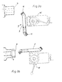
- a turning tool 5 is shown, which is connected to a steel holder 15 by means of clamp connections.
- the steel holder 15 can be pivoted through 90 ° on the support.
- the upper cutting edge 13 of the turning tool 5 is used for the external machining of the workpiece 7.
- the other cutting edge 13 is in a working position for the internal machining of a workpiece 7.
- the turning tool 1, 2, 3, 4, 5, 6 considerably simplifies work on spindle turning machines in particular. It is only necessary to make an adjustment of the turning tool which is retained when the steel holder 15 is pivoted.
- the multiple function of the turning tool 1, 2, 3, 4, 5, 6 also reduces the need for warehousing for turning tools for the user, thereby reducing the costs of turning work to be carried out.
- the chisel holder 9 can also consist of holding rods 17, 18 which are detachably or non-detachably connected to one another, as indicated by dashed lines in FIG. 1a. On the free end portions 19, 20 of the holding rods 17, 18 there is a cutting piece 12. B. butt welds. It is also possible to provide another fixed connection or a releasable connection.
Landscapes
- Engineering & Computer Science (AREA)
- Mechanical Engineering (AREA)
- Cutting Tools, Boring Holders, And Turrets (AREA)
Priority Applications (1)
| Application Number | Priority Date | Filing Date | Title |
|---|---|---|---|
| AT84110381T ATE57861T1 (de) | 1983-09-03 | 1984-08-31 | Drehmeissel. |
Applications Claiming Priority (2)
| Application Number | Priority Date | Filing Date | Title |
|---|---|---|---|
| DE19833331907 DE3331907A1 (de) | 1983-09-03 | 1983-09-03 | Drehmeissel |
| DE3331907 | 1983-09-03 |
Publications (2)
| Publication Number | Publication Date |
|---|---|
| EP0143207A1 true EP0143207A1 (fr) | 1985-06-05 |
| EP0143207B1 EP0143207B1 (fr) | 1990-10-31 |
Family
ID=6208215
Family Applications (1)
| Application Number | Title | Priority Date | Filing Date |
|---|---|---|---|
| EP84110381A Expired - Lifetime EP0143207B1 (fr) | 1983-09-03 | 1984-08-31 | Outil de coupe pour tour |
Country Status (3)
| Country | Link |
|---|---|
| EP (1) | EP0143207B1 (fr) |
| AT (1) | ATE57861T1 (fr) |
| DE (1) | DE3331907A1 (fr) |
Cited By (5)
| Publication number | Priority date | Publication date | Assignee | Title |
|---|---|---|---|---|
| DE3816323A1 (de) * | 1988-05-13 | 1989-11-23 | Stellram Gmbh | Drehmeissel |
| WO1998001250A1 (fr) * | 1996-07-08 | 1998-01-15 | Sandvik Ab (Publ) | Barre d'alesage |
| US11141794B2 (en) * | 2019-07-09 | 2021-10-12 | Carter And Son Toolworks Llc | Handheld wood thread cutting tool |
| JP7719436B1 (ja) * | 2025-02-06 | 2025-08-06 | 株式会社タンガロイ | ヘッド交換式切削工具のシャンク部材、及び切削工具 |
| JP7762355B1 (ja) * | 2025-02-06 | 2025-10-30 | 株式会社タンガロイ | ヘッド交換式切削工具のヘッド、及び切削工具 |
Citations (4)
| Publication number | Priority date | Publication date | Assignee | Title |
|---|---|---|---|---|
| DE520659C (de) * | 1928-12-05 | 1931-03-13 | English Steel Corp Ltd | Einrichtung zum Befestigen von austauschbaren Schneidwerkzeugen mit abgeschraegten Seitenwaenden am Werkzeughalter mit Hilfe eines Mittelbolzens |
| CH254599A (de) * | 1946-10-16 | 1948-05-15 | Goeldi Benedikt | Spanabhebendes Werkzeug mit Haltevorrichtung. |
| FR1276843A (fr) * | 1960-10-12 | 1961-11-24 | Perfectionnements aux barreaux ou lames à tronçonner | |
| FR2300645A1 (fr) * | 1975-02-17 | 1976-09-10 | Wolfor Modern Outillage | Perfectionnements aux porte-lames utilises sur des tours paralleles |
Family Cites Families (7)
| Publication number | Priority date | Publication date | Assignee | Title |
|---|---|---|---|---|
| US1730156A (en) * | 1928-03-17 | 1929-10-01 | Charles W Mcdaniel | Lathe tool holder |
| CH391425A (de) * | 1960-10-11 | 1965-04-30 | Weidmann Ernst | Innendrehstahlhalter mit Drehstahl |
| DE2154270A1 (de) * | 1971-10-30 | 1973-05-03 | Weber Albert | Drehmeissel |
| DE2322825C2 (de) * | 1972-05-08 | 1987-04-23 | Benno Genf/Genève Koch | Schneidwerkzeug für Drehmaschinen |
| DE2533035A1 (de) * | 1975-07-24 | 1977-02-10 | Zapp Werkzeug & Maschf R | Schneidwerkzeug, insbesondere ein- und abstechwerkzeug |
| US4190388A (en) * | 1978-06-02 | 1980-02-26 | Harrison Earl K | Single-point cutting tool |
| DE3504296A1 (de) * | 1985-02-08 | 1986-08-14 | Heidelberger Druckmaschinen Ag, 6900 Heidelberg | Drehmaschinenwerkzeug mit einem schaft als traegermaterial fuer den eigentlichen, die zerspanung vornehmenden drehmeissel |
-
1983
- 1983-09-03 DE DE19833331907 patent/DE3331907A1/de active Granted
-
1984
- 1984-08-31 EP EP84110381A patent/EP0143207B1/fr not_active Expired - Lifetime
- 1984-08-31 AT AT84110381T patent/ATE57861T1/de not_active IP Right Cessation
Patent Citations (4)
| Publication number | Priority date | Publication date | Assignee | Title |
|---|---|---|---|---|
| DE520659C (de) * | 1928-12-05 | 1931-03-13 | English Steel Corp Ltd | Einrichtung zum Befestigen von austauschbaren Schneidwerkzeugen mit abgeschraegten Seitenwaenden am Werkzeughalter mit Hilfe eines Mittelbolzens |
| CH254599A (de) * | 1946-10-16 | 1948-05-15 | Goeldi Benedikt | Spanabhebendes Werkzeug mit Haltevorrichtung. |
| FR1276843A (fr) * | 1960-10-12 | 1961-11-24 | Perfectionnements aux barreaux ou lames à tronçonner | |
| FR2300645A1 (fr) * | 1975-02-17 | 1976-09-10 | Wolfor Modern Outillage | Perfectionnements aux porte-lames utilises sur des tours paralleles |
Cited By (6)
| Publication number | Priority date | Publication date | Assignee | Title |
|---|---|---|---|---|
| DE3816323A1 (de) * | 1988-05-13 | 1989-11-23 | Stellram Gmbh | Drehmeissel |
| WO1998001250A1 (fr) * | 1996-07-08 | 1998-01-15 | Sandvik Ab (Publ) | Barre d'alesage |
| US6076999A (en) * | 1996-07-08 | 2000-06-20 | Sandvik Aktiebolag | Boring bar |
| US11141794B2 (en) * | 2019-07-09 | 2021-10-12 | Carter And Son Toolworks Llc | Handheld wood thread cutting tool |
| JP7719436B1 (ja) * | 2025-02-06 | 2025-08-06 | 株式会社タンガロイ | ヘッド交換式切削工具のシャンク部材、及び切削工具 |
| JP7762355B1 (ja) * | 2025-02-06 | 2025-10-30 | 株式会社タンガロイ | ヘッド交換式切削工具のヘッド、及び切削工具 |
Also Published As
| Publication number | Publication date |
|---|---|
| DE3331907C2 (fr) | 1992-07-02 |
| ATE57861T1 (de) | 1990-11-15 |
| EP0143207B1 (fr) | 1990-10-31 |
| DE3331907A1 (de) | 1985-03-21 |
Similar Documents
| Publication | Publication Date | Title |
|---|---|---|
| DE2523751C2 (de) | Revolverdrehmaschine | |
| DE3220026C2 (fr) | ||
| DE69213006T2 (de) | Abstech- und einstechschneideinsatz mit schneidecken an vier symmetrischen ecken | |
| DE3509378A1 (de) | Bearbeitungsmaschine, wie brennschneidemaschine o.dgl. | |
| DE3034107A1 (de) | Bohrmaschine fuer plattenfoermige oder scheibenfoermige werkstuecke | |
| WO1998008648A1 (fr) | Aleseuse et fraiseuse pour usiner des barres | |
| DE3420531A1 (de) | Drehmaschine | |
| WO2004054753A1 (fr) | Machine-outil pourvue d'un module de remplacement de palettes | |
| DE1777439A1 (de) | Mehrzweck-werkzeugmaschine | |
| EP1210995A1 (fr) | Machine pour l'usinage de pièces, notamment de tôles, avec au moins un dispositif de cintrage et un dispositif d'assemblage | |
| DE3136372A1 (de) | Doppelstaender-portalschleifmaschine | |
| DE3430496A1 (de) | Hilfsvorrichtung zum fraesen von schwalbenschwanznuten bei rechtwinklig zusammenzuzinkenden brettern | |
| EP0143207A1 (fr) | Outil de coupe pour tour | |
| DE2636986C3 (de) | Drehmaschine | |
| DE2616608A1 (de) | Schneidmaschine | |
| DE3419323C2 (de) | Kopierdrehmaschine | |
| DE2026336A1 (de) | Werkzeugmaschine mit mehreren, gleichzeitig arbeitenden Werkzeugen | |
| DE3504296C2 (fr) | ||
| EP0167112B1 (fr) | Procédé et appareil pour fraiser et rainurer des parties d'un cadre en bois | |
| DE559291C (de) | Kopierfraes- oder Schleifmaschine zum Bearbeiten der schmalen Kantenflaechen fassonierter Teile nach einer Schablone | |
| DE3100826A1 (de) | Fraesmaschine mit in mehreren koordinaten beweglichen spindelkoepfen | |
| DE8325409U1 (de) | Drehmeissel | |
| DE1552417C3 (de) | Koordinaten-Bohr- und Fräsmaschine | |
| EP1346804B1 (fr) | Centre d'usinage avec unité d'usinage et unité d'alimentation | |
| DE2322825A1 (de) | Schneidwerkzeug und verfahren zur anformung der schneidkanten desselben |
Legal Events
| Date | Code | Title | Description |
|---|---|---|---|
| PUAI | Public reference made under article 153(3) epc to a published international application that has entered the european phase |
Free format text: ORIGINAL CODE: 0009012 |
|
| 17P | Request for examination filed |
Effective date: 19840925 |
|
| AK | Designated contracting states |
Designated state(s): AT BE CH FR GB IT LI NL SE |
|
| D17P | Request for examination filed (deleted) | ||
| R17P | Request for examination filed (corrected) |
Effective date: 19851204 |
|
| 17Q | First examination report despatched |
Effective date: 19870518 |
|
| GRAA | (expected) grant |
Free format text: ORIGINAL CODE: 0009210 |
|
| AK | Designated contracting states |
Kind code of ref document: B1 Designated state(s): AT BE CH FR GB IT LI NL SE |
|
| PG25 | Lapsed in a contracting state [announced via postgrant information from national office to epo] |
Ref country code: SE Effective date: 19901031 Ref country code: NL Effective date: 19901031 Ref country code: IT Free format text: LAPSE BECAUSE OF FAILURE TO SUBMIT A TRANSLATION OF THE DESCRIPTION OR TO PAY THE FEE WITHIN THE PRESCRIBED TIME-LIMIT;WARNING: LAPSES OF ITALIAN PATENTS WITH EFFECTIVE DATE BEFORE 2007 MAY HAVE OCCURRED AT ANY TIME BEFORE 2007. THE CORRECT EFFECTIVE DATE MAY BE DIFFERENT FROM THE ONE RECORDED. Effective date: 19901031 Ref country code: BE Effective date: 19901031 |
|
| REF | Corresponds to: |
Ref document number: 57861 Country of ref document: AT Date of ref document: 19901115 Kind code of ref document: T |
|
| ET | Fr: translation filed | ||
| NLV1 | Nl: lapsed or annulled due to failure to fulfill the requirements of art. 29p and 29m of the patents act | ||
| GBT | Gb: translation of ep patent filed (gb section 77(6)(a)/1977) | ||
| PG25 | Lapsed in a contracting state [announced via postgrant information from national office to epo] |
Ref country code: LI Effective date: 19910831 Ref country code: GB Effective date: 19910831 Ref country code: CH Effective date: 19910831 Ref country code: AT Effective date: 19910831 |
|
| PLBE | No opposition filed within time limit |
Free format text: ORIGINAL CODE: 0009261 |
|
| STAA | Information on the status of an ep patent application or granted ep patent |
Free format text: STATUS: NO OPPOSITION FILED WITHIN TIME LIMIT |
|
| 26N | No opposition filed | ||
| GBPC | Gb: european patent ceased through non-payment of renewal fee | ||
| PG25 | Lapsed in a contracting state [announced via postgrant information from national office to epo] |
Ref country code: FR Effective date: 19920430 |
|
| REG | Reference to a national code |
Ref country code: CH Ref legal event code: PL |
|
| REG | Reference to a national code |
Ref country code: FR Ref legal event code: ST |